Table of Contents
Advertisement
Quick Links
Advertisement
Table of Contents

Related Manuals for ORBOT SPRAYBORG


Summary of Contents for ORBOT SPRAYBORG
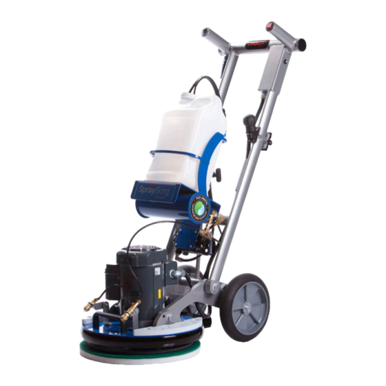
- Page 1 OPERATING MANUAL ( ENG ) V052015...
-
Page 2: Warranty
Periodic maintenance, repair, or replacement of parts due to normal wear and tear. Damage caused by accident, misuse or neglect, fi re, or the fi tting of other than genuine Orbot parts. Defects in other than genuine Orbot parts, repairs, modifi cations or adjustments made by other than a Orbot service engineer or authorized service dealer. -
Page 3: Table Of Contents
TABLE OF CONTENTS Warranty EC Declaration of Conformity How to use this Manual 5 - 7 Safety Technical Details 9 - 16 Operation Unpacking and Initial Operations Pre-Run Inspection Power Cable Connection Spray System Preparation Spray Jets Adjusting Height Process of Cleaning End of Application Storage Lifting and Carrying... -
Page 4: How To Use This Manual
HOW TO USE THIS MANUAL This manual contains the following sections: The PARTS LIST section contains assembled parts illustrations and corresponding parts list. The parts • How to Use This Manual lists include a number of columns of information: • Safety •... -
Page 5: Safety
SAFETY IMPORTANT SAFETY INSTRUCTIONS When using this machine, basic precaution must always be followed, including the following: READ ALL INSTRUCTIONS BEFORE USING THIS MACHINE. WARNING To reduce the risk of fire, electric shock, or injury: • Use only indoors. Do not use outdoors or expose to rain. •... -
Page 6: Hazard Intensity Level
SAFETY The following symbols are used throughout this guide as indicated in their descriptions: HAZARD INTENSITY LEVEL There are three levels of hazard intensity identified by signal words -WARNING, CAUTION, and FOR SAFETY. The level of hazard intensity is determined by the following definitions: WARNING WARNING - Hazards or unsafe practices CAN result in severe personal injury or death. - Page 7 SAFETY GROUNDING INSTRUCTIONS 120V THIS PRODUCT IS FOR COMMERCIAL USE ONLY ELECTRICAL: In the USA this machine operates on a 15 amp nominal 120V, 60 hz, A.C. power circuit. The amp, hertz, and voltage are listed on the data label found on each machine.
-
Page 8: Technical Details
TECHNICAL DETAILS ITEM MEASURE Motor 1HP, 100-240V/50-60Hz, 6 amps (50Hz)/11amp (60Hz) 1725 (60Hz)/1400 (50Hz) Base Diameter 17“/43 cm Orbital Diameter 3/8” (9.5 mm) Weight 102 Lbs./46.7 kg Height 48” (122 cm) Length 29” (75 cm) Wheels 10”/25 cm Diameter, resistant to chemicals Decibel Rating 59 dB... -
Page 9: Operation
OPERATION Unpacking and Initial Operations Open the shipping box on both sides, remove the packaging material and roll the machine out of the box. Pre-Run Inspection Before each use, inspect the accessory such as the pad driver for cracks, tears, or excess wear. If the machine or accessory is dropped, inspect for damage to install an undamaged accessory. -
Page 10: Spray Jets
OPERATION pressure. The further you move the lever counterclockwise upwards, the higher the water pressure. A horizontal position means maximum water output at maximum pressure. To turn the machine on, press the power button on the end of the left handle. Spray Jets Adjust the spray jets on the machine base to the desired position. -
Page 11: End Of Application
OPERATION CAUTION Make sure the surface to be cleaned is not damaged by the increase in pressure. Omit this measure on very sensitive floors. End of the Application Turn off the machine by putting the on/off switch to “O”. If a cleaning solution was used, fill bottle cartridge with water and spray out system for 30 seconds. -
Page 12: Weight Kit Installation
OPERATION wheels down first, followed by the machine base. WARNING Make sure not to grip too close to the machine base. If the base should flip upwards it can cause serious hand injuries. Make sure you lift the machine with a back-friendly posture. Secure machine firmly so it will not move. -
Page 13: Attaching And Removing The Driver Plates
OPERATION Mount the brush with the same countersink screws used for mounting the driver plates. • NOTE: Tighten the screws sufficiently to avoid disengagement of the brush from the machine during operation. To avoid stripping the screws do not over tighten. An electric screwdriver with a clutch will ensure that stripping will not occur. -
Page 14: Driver Plates
OPERATION Driver Plates WARNING Exclusively use designed driver plates only. The use of other driver plates will damage the machine and its mechanical action. The driver plates are fastened on the machine base with four countersink screws. Standard Driver Plate The standard driver plate (17”... -
Page 15: Melamine Pads
Marble, terrazzo, travertine, limestone, and more. Each pad cleans an approximate area of 5000sq.ft. (460m²) depending on floor type and level of soil. • NOTE: StoneFlash pads require the use of the Orbot Weight Kit (sold separately). -
Page 16: Scrub Brush
OPERATION Scrub Brush The bristles of the brush are made of high quality nylon. The unique brush design is ideal for cleaning tile and grout, smooth concrete, rubber flooring, and micro-porous surfaces such as porcelain and safety tiles. It can also be used for any other hard surfaces. -
Page 17: Operation/Maintenance
OPERATION / MAINTENANCE APPLICATION ON DIFFERENT FLOOR TYPES Carpet Cleaning Vacuum the carpet thoroughly before cleaning. Large dirt particles are removed, allowing the application to be more effective. Apply solution as you move forward. The carpet should be cleaned by going forward and backwards two to three times, while applying solution on the first pass in order to keep the drying time low. - Page 18 PARTS ITEM NO PART NUMBER DESCRIPTION 1026 ROD, HANDLE 1022 LATCH BODY PULL 1025 LATCH, PULL 1027 COLLAR, HANDLE LATCH 1028 SCREW, 1/2-13 X 1-3/4",HH, STL, ZNPLT 1029 WASHER, NYLON, 1/2", LATCH 1030 NUT, 1/2-13 HEXTHIN NYLOCK STL ZNPLT 1023 SCREW, 1/2-13 X 2",HH, STL, ZNPLT 1024 WASHER, NYLON, 1/2", LATCH MOUNT...
- Page 19 PARTS...
- Page 20 PARTS ITEM NO PART NUMBER QTY DESCRIPTION 2000 CAGE ASSY, BOTTLE HOLDER 2024 SPRING, BOTTLE HOLDER 2023 DAMPNER, RUBBER 2019 BOTTLE, CARTRIDGE, 3 GAL 2018 BOTTLE CAP, ASSY 2020 SCREW, 1/2-13 X 4-3/8",HH, STL, ZNPLT 2022 WASHER, NYLON, CAGE 2021 WASHER, 5/8ID X 1-3/4OD X .134L, FLT, 2025 NUT, 1/2-13 HEXTHIN NYLOCK STL ZNPLT...
- Page 21 PARTS...
- Page 22 PARTS ITEM NO PART NUMBER DESCRIPTION 3000 PLATE, MOTOR MOUNT 3001 BUMPER SET 3045-14 PLATE, BASE, WEIGHT 3004 HANDLE, BASE 3002 SCREW, 1/4-20 X 1-1/2", PHTRH,SS 3045-06 NUT, 1/4-20 X 5/16, TEE, 4 PRONG, ZNPLT 3034 SCREW,3/8-16 X 3/4",HH, STL, GRD8, YL, 3035 WASHER, 3/8, FLAT 3003...
- Page 23 PARTS...
- Page 24 PARTS ITEM NO PART NUMBER DESCRIPTION 4003 WHEEL, 10” 4002 ROD, WHEEL 3 - 1 3007-051 LEFT EAR 3 - 2 3007-052 RIGHT EAR (with pin) 4005 SCREW, 1/2-13 X 3-3/4",HH, STL, ZNPLT 4004 WASHER, NYLON, WHEEL 3034 SCREW,3/8-16 X 3/4",HH, STL, GRD8, YL, 3008 WASHER, 3/8, FLAT 4009...
- Page 25 PARTS...
- Page 26 PARTS ITEM NO PART NUMBER DESCRIPTION 1001 HINGE, HANDLE 1002 SCREW, 5/16-24 X 1/2",HHMS, STL, ZNPLT 1003-10 LATCH, LOWER ASM, HANDLE 1003-12 SCREW, 10-32 X 1/4",SCHCS, STL, ZNPLT 1019 SCREW, LOWER HANDLE 1021 WASHER, NYLON 1020 NUT, 1/2-13 HEXTHIN NYLOCK STL ZNPLT 4001 PLATE, ARMS, LIFT, LH 4000...
- Page 27 PARTS...
- Page 28 PARTS ITEM NO PART NUMBER DESCRIPTION 1000-06U HANDLE ASM, UPPER, W/ELEC BOX 3028 HARNESS, MAIN HANDLE 1007 SWITCH, DP, 2POS, ROCKER SPR 1008 HARNESS, SPRAYER SWITCH 1005-03 SWITCH, DP POS, ROCKER 1006 HARNESS, ON/OFF SWITCH 1010 BREAKER, 20A 125/250VAC 32VDC 1011 PLATE, COVER, ELECTRICAL BOX 1015...
- Page 29 PARTS...
- Page 30 PARTS ITEM NO PART NUMBER DESCRIPTION 3023-05 3023-04 COVER, FAN MOTOR 3023-03 FAN, MOTOR 3030 NUT, 3/4”, CONDUIT 3023-06 SCREW, MOTOR LID 3032 CORD, BLUE PLUG, 100-120V 3033 CORD, BLACK PLUG, 100-120V 3031 CORD GRIP, 3/4", MOTOR 3029 CORD GRIP, 90 DEG, MOTOR 3024 SCREW, 3/8-24 X 1-1/2"...
- Page 31 PARTS...
- Page 32 PARTS ITEM NO PART NUMBER DESCRIPTION 3019 FITTING, TEE, SPRAY NOZZLES 3021 FITTING, 90, SPRAY NOZZLES 3022 HOSE, SPRAY NOZZLES 3022-01 HOSE, SPRAY NOZZLES CAGE 3009 PLATE, ANGLE, NOZZLE BASE 6 - 1 3010-001 SPRAY BRACKET, TOP LEFT 6 - 2 3010-002 SPRAY BRACKET, TOP RIGHT 3016...
- Page 33 PARTS...
- Page 34 PARTS ITEM NO PART NUMBER DESCRIPTION 3038 DRIVER, DISK, 15” 3040 DRIVER, VELCRO PLATE, 15” 3026 ASSY, COUNTERWEIGHT, 17 DISK 3025 SHAFT SUPPORT 3026-17 SCREW, 1/4-20 X 3/4, PHFLHMS, SS 3047 SCREW, 1/4-20 X 1", PHFLH, SS 3043 NUT, 1/4-20 X 5/16, TEE, 4 PRONG, ZNPLT 3042 SCREW, 1/4-20 X 3/8", PHTRH, SS...
- Page 35 PARTS...
- Page 36 PARTS ITEM NO PART NUMBER DESCRIPTION 2010 PUMP, 90PSI, 120V 2008 VALVE, FLOW CONTROL, 3-WAY 2008-01 COUPLER, QD, FLOW CONTROL 2008-02 NIPPLE, 1/4”, HEX 2008-03 COUPLER, FLOW CONTROL 2007 ELBOW, 1/4”, 90 2000-05 WASHER, 1/2ID X 3/4" OD, DSP, ZNPLT 2008-04 FITTING, ELBOW, 1/4”, 90 2016...
- Page 37 PARTS...
-
Page 38: Wiring Diagram
WIRING DIAGRAM ON/OFF SWITCH SPRAY SWITCH 1 (BLK) 2 (WHT) 1 (BLK) 2 (WHT) Power Cord from Wall Circuit Breaker Ground Terminal Strip inside handle wiring box 4 (RED) 1 (BLK) Ground 3 (BLU) 2 (WHT) Ground 5(YLW) No Connection (Insulated) 6 (BRN) No Connection (Insulated) Ground Motor Wiring Box... -
Page 39: Notes
NOTES...
Need help?
Do you have a question about the SPRAYBORG and is the answer not in the manual?
Questions and answers