Table of Contents
Advertisement
Available languages
Available languages
Quick Links
Gruppi Termici a gasolio, in ghisa, a condensazione
Cast iron condensing diesel thermal units
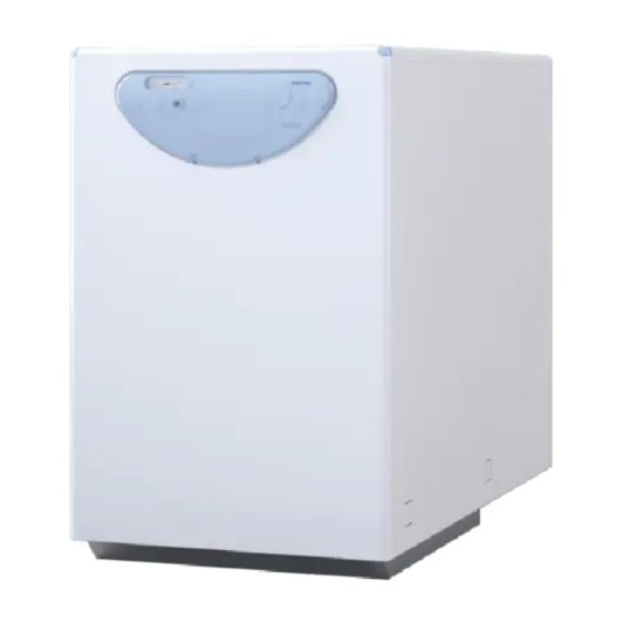
DUETTO HE 25-35 EV
MANUALE PER L'USO, L'INSTALLAZIONE E LA MANUTENZIONE
USER, INSTALLATION AND SERVICING INSTRUCTIONS
IT
EN
Per la consultazione della
documentazione visita il
nostro sito www.sime.it
To consult the documentation,
visit our website www.sime.it
Fonderie SIME S.p.A.
6331818 - 04/2021 - R0
ISTRUZIONI ORIGINALI - TRANSLATION OF THE ORIGINAL INSTRUCTIONS
Advertisement
Chapters
Table of Contents

Related Manuals for Sime DUETTO HE 25 EV


Summary of Contents for Sime DUETTO HE 25 EV
- Page 1 MANUALE PER L’USO, L’INSTALLAZIONE E LA MANUTENZIONE USER, INSTALLATION AND SERVICING INSTRUCTIONS Per la consultazione della documentazione visita il nostro sito www.sime.it To consult the documentation, visit our website www.sime.it Fonderie SIME S.p.A. 6331818 - 04/2021 - R0 ISTRUZIONI ORIGINALI - TRANSLATION OF THE ORIGINAL INSTRUCTIONS...
- Page 3 – si riserva di va- Fonderie SIME S.p.A. qualificato. riare in qualunque momento e senza preavviso i propri prodotti nell’intento – Il non utilizzo dell’apparecchio, per un di migliorarli senza pregiudicarne le lungo periodo, comporta l’effettuazio-...
- Page 4 DIVIETI È VIETATO È VIETATO – L’uso dell’apparecchio ai bambini di – Modificare i dispositivi di sicurezza o di età inferiore a 8 anni. L’apparecchio regolazione senza l’autorizzazione e le può essere utilizzato da bambini di età indicazioni del costruttore dell'appa- non inferiore a 8 anni e da persone con recchio.
- Page 5 Gentile Cliente, STRUTTURA DEL MANUALE La ringraziamo per aver acquistato il Gruppo Termico Sime Questo manuale è organizzato nel modo sotto evidenziato. , un apparecchio a condensazione, con caratte- DUETTO HE EV ristiche tecniche e prestazionali in grado di soddisfare le Sue...
-
Page 7: Table Of Contents
ISTRUZIONI PER L'USO INDICE OPERARE CON IL GRUPPO TERMICO DUETTO HE 25-35 EV SPEGNIMENTO Quadro comandi ....... . 8 Spegnimento temporaneo . -
Page 8: Operare Con Il Gruppo Termico Duetto He 25-35 Ev
OPERARE CON IL GRUPPO TERMICO DUETTO HE 25-35 EV – richiudere il rubinetto di carico (B). Quadro comandi Il Quadro Comandi permette a tutti gli operatori di effettuare le regolazioni necessarie alla gestione dei Gruppi Termici Sime e degli impianti collegati. DUETTO HE EV Fig. 3 Fig. -
Page 9: Regolazione Della Temperatura Riscaldamento
Gruppo Termico effettuerà un arresto di blocco e la ; per regolare la temperatura dell'acqua sani- DUETTO HE 25 EV spia di segnalazione rossa (7) del quadro comandi si accenderà. taria è necessario agire sul regolatore di portata (1) del pres-... -
Page 10: Bassa Pressione Impianto (Reintegro)
SPEGNIMENTO 1.6.3 Bassa pressione impianto (reintegro) Verificare sul manometro (A) che la pressione impianto, a fred- do, sia compresa tra 1 e 1,2 bar (98-117,6 kPa) . Se la pressione Spegnimento temporaneo è inferiore a quanto indicato sopra, il pressostato acqua blocca il funzionamento del bruciatore (LED di segnalazione arancione Nel caso di assenze temporanee, fine settimana, brevi viaggi, (1) acceso). -
Page 11: Manutenzione
MANUTENZIONE SMALTIMENTO Regolamentazioni Smaltimento dell’apparecchio (Direttiva Europea 2012/19/UE) Per un funzionamento efficiente e regolare dell'apparecchio è consigliabile che l'Utente incarichi un Tecnico Professional- L'apparecchio ed i dispositivi elettrici ed elet- mente Qualificato affinché provveda, con periodicità ANNUALE , tronici, provenienti da nuclei domestici o clas- alla sua manutenzione. - Page 13 DESCRIZIONE DELL'APPARECCHIO INDICE 5.12 Regolazione pompa di circolazione ....22 DESCRIZIONE DELL'APPARECCHIO 5.12.1 Selezione del modo operativo e della curva Caratteristiche....... . . 14 caratteristica.
-
Page 14: Descrizione Dell'apparecchio
Caratteristiche I Gruppi Termici, in ghisa e a condensazione, Sime DUETTO HE EV sono sistemi integrati con bruciatore di gasolio, ad aria soffiata Low NOx. Sono equipaggiati inoltre con un recuperatore di calore, lato fumi, che li classifica “a condensazione”. Sono destinati a chi tiene in opportuna considerazione le prestazioni, la silenziosità... -
Page 15: Dispositivi Di Controllo E Sicurezza
– termostato limite mente qualificato utilizzando solamente componenti originali Sime . Identificazione I Gruppi Termici DUETTO HE EV sono identificabili attraverso: è posizionata all’esterno della confezione e riporta il codice, il numero di matricola del Gruppo Termico e il codice... -
Page 16: Struttura
Struttura DUETTO HE 25 EV 18 17 DUETTO HE 35 EV 9 10 Pozzetto portasonde Attacco scarico fumi Quadro comandi Rubinetto carico impianto Tubo mandata impianto (M) Pannello superiore Valvola di sfiato automatico Ritorno impianto (R) Fori per movimentazione Sfiato manuale... - Page 17 Bruciatore Targa dati tecnici Ugello Targa matricola e codice Gruppo elica di turbolenza Gruppo elettrodi Vite di fissaggio boccaglio Vite di fissaggio gruppo elica di turbolenza Boccaglio Vite fissaggio elettrodi 14 15 18 17 Apparecchiatura elettrica di co- Vite regolazione aria Presa 7 poli mando e controllo Corpo alloggiamento girante...
-
Page 18: Caratteristiche Tecniche
Caratteristiche tecniche DUETTO HE EV DESCRIZIONE CERTIFICAZIONE Paesi di destinazione IT – ES – PT – EN – FR – NL – HR – DK – EL Combustibile Gasolio Numero PIN 1312CS196R Classificazione apparecchio B23P - C23P Potenza utile nominale sanitario 26,2 34,8 Classe NO... -
Page 19: Regolazioni Del Bruciatore A Varie Altitudini Di Installazione
- CO (ppm) - NOx (ppm) - indice di Bacharach - temperatura fumi di scarico. ATTENZIONE Tutte le operazioni devono essere eseguite esclusivamente dal Servizio Tecnico Sime o da Personale Professionalmente Qualificato, seguendo le istruzioni presenti in questo manuale al paragrafo. -
Page 20: Circuiti Idraulici Di Principio
Circuiti idraulici di principio DUETTO HE 25 EV DUETTO HE 35 EV LEGENDA: Corpo Gruppo Termico Pressostato acqua impianto Mandata impianto Rubinetto carico impianto Pressostato acqua sanitario Ritorno impianto Valvola sicurezza (VS) Bollitore istantaneo Entrata sanitario Valvola sfiato automatica Valvola di ritegno... -
Page 21: Vaso Di Espansione
Vaso di espansione 5.11 Pompa impianto alta efficienza Il vaso di espansione installato sul Gruppo Termico ha le se- La pompa ad alta efficienza è corredata dai LED di segnalazione guenti caratteristiche: (1), (2), (3) e dal tasto di comando (4). DUETTO HE EV Descrizione Capacità... -
Page 22: Regolazione Pompa Di Circolazione
Pressione differenziale variabile Δp-v (I, II, III) 5.12 Regolazione pompa di circolazione Consigliata in caso di sistemi di riscal- damento a doppia mandata con radiato- 5.12.1 Selezione del modo operativo e della curva ca- ri, per la riduzione dei rumori di flusso ratteristica sulle valvole termostatiche. -
Page 23: Bloccare/Sbloccare Il Tasto
5.13.3 Bloccare/sbloccare il tasto ATTENZIONE Se l’anomalia non si risolve, contattare il Centro As- Il blocco tastiera viene attivato premendo a lungo (8 secondi) sistenza. il tasto di comando (4) e blocca le impostazioni della pompa. Il blocco tastiera protegge da modifiche involontarie o non auto- La curva portata-prevalenza residua a disposizione dell'impian- rizzate alla pompa. -
Page 24: Schema Elettrico
5.14 Schema elettrico 5.14.1 Gruppo Termico 230V-50Hz SPAC BR or GR Bruciatore Pompa bollitore (alta efficien- Termostato riscaldamento Cronotermostato programma- Termostato sicurezza tore Pompa impianto (alta efficien- Termostato di minima TMIN Interruttore estate/inverno Termostato limite Fusibile (2AT - 250V) Relè Valvola pressostatica Interruttore generale Spia presenza tensione... -
Page 25: Bruciatore
5.14.2 Bruciatore Sensore fiamma Motore ventilatore Trasformatore Riscaldatore del combustibile Elettrovalvola gasolio presa 7 poli per connessione al quadro comandi del Gruppo Termico Fig. 27... - Page 27 ISTRUZIONI PER L'INSTALLAZIONE E LA MANUTENZIONE INDICE INSTALLAZIONE MANUTENZIONE Ricevimento del prodotto ......28 Regolamentazioni ......38 Pulizia interna .
-
Page 28: Installazione
Ricevimento del prodotto Gli apparecchi Sime DUETTO HE EV vengono forniti in collo unico, protetti da un sacco di nylon, e posti su pallet in legno. Fig. 29 DUETTO HE EV Descrizione... -
Page 29: Locale D'installazione
ATTENZIONE Nuova installazione o installazione in sosti- Utilizzare attrezzature e protezioni antinfortunistiche tuzione di altro apparecchio adeguate sia per togliere l'imballo, sia per la movi- Quando i gruppi termici DUETTO HE EV vengono installati su im- mentazione dell'apparecchio. Rispettare il peso mas- pianti vecchi o da rimodernare, è... -
Page 30: Trattamento Acqua Impianto
– È utile annotare le quantità di acqua di riempimen- to, di rabbocco e i valori della qualità dell’acqua uti- lizzata. Collegamenti idraulici Le dimensioni degli attacchi idraulici delle caldaie Sime DUETTO sono riportate di seguito. H = x-y HE EV Fig. -
Page 31: Collegamento Del Circuito Combustibile Alla Pompa Del Bruciatore
Lunghezza tubo (m) H (m) Ø6 mm Ø8 mm Ø10 mm ATTENZIONE – L'impianto di alimentazione del combustibile deve essere adeguato alla portata del bruciatore e deve essere dotato di tutti i dispositivi di sicurezza e di controllo prescritti dalle Norme vigenti nel paese di utilizzo dell'apparecchio. -
Page 32: Scarico Fumi E Aspirazione Aria Comburente
In fat ti, se non è ese gui ta con gli I Gruppi Termici Sime DUETTO HE EV sono classificati di "Tipo B" op por tu ni cri te ri, si pos so no ave re di sfun zio ni nel bru cia to re, (B23P) e di "TIPO C"... -
Page 33: Raccolta/Scarico Condensa
Ø80 mm, non dovrà es- sere superiore a 7,0 metri + n°2 curve a 90°. AVVERTENZA Utilizzare esclusivamente accessori originali Sime e assicurarsi che il collegamento sia realizzato in ma- niera corretta, così come indicato nelle istruzioni for- nite a corredo degli accessori. -
Page 34: Collegamenti Elettrici
6.13 Riempimento e svuotamento I Gruppi Termici Sime DUETTO HE EV sono dotati del dispositivo di riempimento impianto. 6.13.1 Operazioni di RIEMPIMENTO IMPIANTO Prima di effettuare le operazioni di riempimento: –... -
Page 35: Messa In Servizio
MESSA IN SERVIZIO AVVERTENZA – regolare il termostato riscaldamento (1) a circa 3/4 del campo di regolazione (circa 75°C) Le operazioni di messa in servizio e prima accensione – posizionare l’interruttore principale (2) dell’apparecchio su devono essere effettuate SOLO da Personale Profes- "1"... -
Page 36: Regolazione Bruciatore
7.3.3 Controllo depressione pompa Regolazione bruciatore Il vacuometro per il controllo della depressione della pompa 7.3.1 Posizione della serranda dell’aria deve essere collegato al punto (5). La depressione massima consentita è di 0,4 bar. La serranda dell'aria si regola ruotando la vite (1) con la chiave Con depressione più... -
Page 37: Regolazione Della Combustione
7.3.5 Regolazione della combustione I bruciatori lasciano la fabbrica tarati in accordo al paragrafo “Regolazioni del bruciatore a varie altitudini di installazione”. In caso di condizioni di temperatura esterna tali che possano influenzare la combustione, si consiglia di regolare la CO secondo lo schema seguente. -
Page 38: Manutenzione
MANUTENZIONE Regolamentazioni Per un funzionamento efficiente e regolare dell'apparecchio è consigliabile che l'Utente incarichi un Tecnico Professional- mente Qualificato affinché provveda, con periodicità ANNUALE , alla sua manutenzione. AVVERTENZA – Le operazioni di seguito descritte devono essere effettuate SOLO da personale professionalmente qualificato con l’OBBLIGO di indossare adeguate pro- tezioni antinfortunistiche. -
Page 39: Pulizia Condotto Fumi
8.2.3 Pulizia condotto fumi 8.2.4 Pulizia e sostituzione componenti testa di com- bustione Per pulire i condotti per il passaggio dei fumi procedere nel se- Per effettuare la pulizia della testa di combustione: guente modo: – svitare la vite (8) ed estrarre il bruciatore (9) –... -
Page 40: Verifica Posizione Gruppo Elica Di Turbolenza
8.2.5 Verifica posizione gruppo elica di turbolenza 8.2.6 Verifica posizione del boccaglio Per verificare la posizione del gruppo elica di turbolenza: Verificare che la distanza (A), tra il boccaglio (26) e l'ugello (20), – smontare il boccaglio, come descritto nel paragrafo "Pulizia e sia quella prevista dalla dima (25), come illustrato in figura. -
Page 41: Sostituzione Della Bobina
8.2.8 Sostituzione della bobina 8.2.10 Pulizia della girante Per sostituire la bobina: Per pulire la girante del ventilatore: – togliere il connettore (1) – svitare le viti (1) e rimuovere il condotto di aspirazione aria (2) – rimuovere il dado (2) con la chiave fornita a corredo –... -
Page 42: Pulizia Del Filtro Pompa
Nella tabella di seguito sono riportati i componenti soggetti a usura e il loro ciclo di vita, al termine del quale è opportuno che vengano sostituiti esclusivamente dal Servizio Tecnico Sime o da Personale Professionalmente Qualificato Ciclo di vita... -
Page 43: Eventuali Anomalie E Rimedi
Eventuali anomalie e rimedi 8.3.1 Bruciatore Richiesta di Consenso Motore calore Sì riscaldatore Sì Sì si avvia (entro 400s) Verifica che Pompa Sostituire Motore Sì il LED verde bloccata condensatore bloccato sia acceso motore Verifica che Riscaldatore Sì Sì il LED verde Sì... - Page 44 Richiesta di calore Sì Blocco C’è un falso Rimuovi la Avviamento Fase di Sì durante la Sì segnale di Sì causa del Sì Motore riscaldamento fase di pre- fiamma falso segnale ventilazione di fiamma Verifica la funzionalità del sensore fiamma Sostituisci Il sensore Sì...
-
Page 45: Pompa
8.3.2 Pompa Colore LED Stato della pompa Eventuale anomalia Possibile rimedio Il sistema idraulico della pompa Funzionamento turbina viene alimentato, ma la pompa non - Verificare la tensione di rete ha tensione di rete Rosso-Verde lam- Funzionamento a secco Aria nella pompa - Verificare l’assenza di perdite nell’impianto peggiante - Verificare la tensione di rete... -
Page 46: Impianto
8.3.3 Impianto Tipo di anomalia o guasto Causa Rimedio - Verificare pulizia corpo bruciatore Odore di prodotti incombusti Dispersione fumi in ambiente - Verificare pulizia ed ermeticità scarico fumi e generatore - Controllare qualità combustione Bruciatore mal regolato - Controllare regolazione del bruciatore (analisi fumi) Il generatore si sporca in breve tempo Canna fumaria intasata - Pulire condotto fumi... - Page 49 – If the appliance is not used for a long – reserves the right Fonderie SIME S.p.A. period of time, at least one of the fol- to make improvements to its prod- lowing operations must be carried out: ucts at any time without prior notice, - set the main system switch to "OFF";...
- Page 50 RESTRICTIONS IT IS FORBIDDEN IT IS FORBIDDEN – To allow children under the age of 8 to – To modify the safety or adjustment use the appliance. The appliance can devices without authorization and in- be used by children no younger than structions from the manufacturer.
- Page 51 Dear Customer, MANUAL STRUCTURE Thank you for purchasing the Sime DUETTO HE EV thermal unit, a This manual is organized as follows. condensing device with technical and performance characteris- tics capable of satisfying your space heating and instant domes- tic hot water requirements with the utmost safety and limited USER INSTRUCTIONS running costs.
- Page 53 USER INSTRUCTIONS TABLE OF CONTENTS OPERATING WITH THE DUETTO HE 25-35 EV THERMAL UNIT SHUTDOWN Control panel ........54 Temporary shutdown .
-
Page 54: Operating With The Duetto He 25-35 Ev Thermal Unit
OPERATING WITH THE DUETTO HE 25-35 EV THERMAL UNIT – close the filling valve (B). Control panel The control panel enables all operators to make the necessary adjustments for managing Sime DUETTO HE EV thermal units and the systems connected to them. Fig. 3 Fig. 1 Ignition ;... -
Page 55: Adjusting The Heating Temperature
Adjusting the hot water temperature 1.6.2 Burner lock-out DUETTO HE 25 EV ; to adjust the domestic hot water temperature, Should any faults occur during its ignition or operation, the move the flow regulator (1) of the water pressure switch to in- thermal unit will perform a lock-out and the red signalling in- crease or decrease the water flow and thus the temperature. -
Page 56: System Low Pressure (Replenishment)
SHUTDOWN 1.6.3 System low pressure (replenishment) Check on the pressure gauge (A) that the pressure of the sys- tem, when cold, falls between 1 and 1.2 bar (98–117.6 kPa) . If Temporary shutdown the pressure is lower than the above value, the water pressure switch will stop the burner’s operation (orange signalling LED If the user is away temporarily, for a weekend, short trip etc and (1) lit). -
Page 57: Maintenance
MAINTENANCE DISPOSAL Adjustments Disposal of the equipment (European Di- rective 2012/19/EU) For the appliance to operate correctly and efficiently it is recom- mended that the User calls upon the services of a Professionally At the end of their life span, the appliance Qualified Technician to carry out ANNUAL maintenance. - Page 59 DESCRIPTION OF THE APPLIANCE TABLE OF CONTENTS 5.12 Setting the circulation pump ..... 68 DESCRIPTION OF THE APPLIANCE 5.12.1 Selecting the operating mode and the Characteristics .
-
Page 60: Description Of The Appliance
Characteristics The Sime DUETTO HE EV cast iron and condensing thermal units are integrated systems with diesel Low NOx blown-air burner. They are also equipped with a heat recovery device, flue gas side, which classifies them as “condensing”. They are specially designed for users who privilege high performances, silent operation and compact dimensions. -
Page 61: Check And Safety Devices
– heating thermostat (min 45°C - max 85°C) WARNING – water pressure switch Safety device may only be replaced by professional – minimum-temperature thermostat qualified personnel using Sime original spare parts. – temperature-limit thermostat Identification appliances can be identified by: DUETTO HE EV... -
Page 62: Structure
Structure DUETTO HE 25 EV 18 17 DUETTO HE 35 EV 9 10 Thermowell Smoke outlet fitting Control panel System filling valve System delivery pipe (M) Top panel Automatic bleed valve System return (R) Holes for handling Manual relief valve... - Page 63 Burner Data plate Nozzle Serial number and code plate Turbulence propeller assembly Electrode assembly Nose fixing screw Fixing screw for turbulence propeller assembly Nose Electrodes fixing screw 14 15 18 17 Electrical control and command Air regulation valve 7-pin socket equipment Impeller housing body Foot...
-
Page 64: Technical Features
Technical features DUETTO HE EV DESCRIPTION CERTIFICATIONS Country of intended installation IT – ES – PT – EN – FR – NL – HR – DK – EL Fuel Diesel PIN number 1312CS196R Appliance classification B23P - C23P DHW rated useful heat output 26,2 34,8 Class NO... -
Page 65: Adjusting The Burner At Various Installation Altitudes
- NOx (ppm) - Bacharach index - flue gas temperature. WARNING All operations must be carried out exclusively by the Sime Technical Support Service or by professionally qualified personnel, according to the instructions appearing in this manual under the paragraph... -
Page 66: Main Hydraulic Circuits
Main hydraulic circuits DUETTO HE 25 EV DUETTO HE 35 EV KEY: Thermal unit body System water pressure switch System delivery System filling valve Hot water pressure switch System return Safety valve (VS) Instantaneous calorifier Hot water inlet Automatic bleed valve... -
Page 67: Expansion Vessel
Expansion vessel 5.11 High-efficiency system pump The expansion vessel installed on the Thermal unit has the fol- The high-efficiency pump is fitted with signalling LEDs (1), (2), lowing characteristics: (3) and with the command button (4). DUETTO HE EV Description Total capacity 10,0 Prefilling pressure... -
Page 68: Setting The Circulation Pump
Variable differential pressure Δp-v (I, II, III) 5.12 Setting the circulation pump Recommended in case of heating sys- tems with double delivery and radiators, 5.12.1 Selecting the operating mode and the charac- for the reduction of flow noises on the teristic curve thermostatic valves. -
Page 69: Locking/Unlocking The Button
5.13.3 Locking/unlocking the button WARNING If the fault persists, please contact the Technical As- The keypad lock is activated by pressing the command button (4) sistance Centre. for 8 seconds and it blocks the pump settings. The keypad lock protects the pump against involuntary/unauthorised changes to The flow-residual head curve available for the heating system is the pump. -
Page 70: Wiring Diagram
5.14 Wiring diagram 5.14.1 Thermal unit 230V-50Hz SPAC BR or GR Burner Calorifier pump (high-efficien- Heating thermostat Programmer timer-controlled Safety thermostat thermostat System pump (high-efficiency) Minimum-temperature ther- TMIN Summer/winter switch Relè mostat Fuse (2,5AT - 250V) Voltage indicator light Temperature-limit thermostat Main switch Burner lock-out indicator light Pressostatic valve... -
Page 71: Burner
5.14.2 Burner Flame sensor Fan motor Transformer Fuel heater Diesel solenoid valve 7-pole socket for connection to the control panel of the Thermal Group Fig. 27... - Page 73 INSTALLATION AND SERVICING INSTRUCTIONS TABLE OF CONTENTS INSTALLATION MAINTENANCE Receiving the product ......74 Adjustments.
-
Page 74: Installation
Service or by qualified professionals who MUST suitable protective safety equipment. wear Receiving the product Appliances Sime DUETTO HE EV are supplied in a single package, protected by a nylon cover, placed on wooden pallets. Fig. 29 DUETTO HE EV... -
Page 75: Installation Room
WARNING New installation or installation of a re- Use suitable tools and accident protection when re- placement appliance moving the packaging and when handling the appli- When DUETTO HE EV thermal units are installed on old systems ance. Observe the maximum weight that can be lifted or systems that need to be upgraded, we recommend checking per person. -
Page 76: Water System Treatment
– It is useful to note the quantities of water to fill the system and top it up, and the values of the quality of water used. Plumbing connections The dimensions of the water fittings of Sime DUETTO HE EV boil- ers are given below. H = x-y Fig. 33... -
Page 77: Connecting The Fuel Circuit To The Burner Pump
Lunghezza tubo (m) H (m) Ø6 mm Ø8 mm Ø10 mm WARNING – The fuel supply system must be sized in relation to the burner flow rate and must be equipped with all the safety and control devices envisaged in the standards in force in the country where the appli- ance is used. -
Page 78: Smoke Outlet And Combustion Air Inlet
“Type B” Sime DUETTO HE EV malfunctions, noise amplification and the build up of soot, con- (B23P) and “Type C” (C23P), while the smoke discharge and densate and deposits. -
Page 79: Condensate Outlet/Collection
The maximum allowed length (L) of the air intake pipe with Ø80 mm diameter must not exceed 7,0 metres + 2 x 90° elbows. CAUTION Only use original Sime accessories and make sure that the connection is made correctly, as explained in the instructions supplied with the accessories. WARNINGS –... -
Page 80: Electrical Connections
Electrical connections It is compulsory: thermal units require the connections Sime DUETTO HE EV – to use an omnipolar cut-off switch, disconnect shown below, which must be carried out by the installer or by switch, in compliance with EN standards (contact professionally qualified personnel. -
Page 81: Commissioning
COMMISSIONING CAUTION – adjust the heating thermostat (1) to roughly 3/4 of the adjust- ment range (circa 75°C) The commissioning and initial start-up operations – shift the appliance’s main switch (2) to "1" (on) and check that must be carried out ONLY by professionally qualified the green signalling LED (3), situated on the control panel, is personnel who must follow the indications provided lit. -
Page 82: Adjusting The Burner
7.3.3 Checking the pump’s negative pressure Adjusting the burner The vacuum gauge for checking the pump’s negative pressure 7.3.1 Air shutter position must be connected to point (5). The maximum allowed negative pressure is 0,4 bar. The air shutter can be adjusted by turning the screw (1) with the With a higher negative pressure, diesel turns into gas, causing Allen key (2) provided:: cavitation of the pump and damaging it as a result. -
Page 83: Adjusting The Combustion
7.3.5 Adjusting the combustion The burners leave the factory calibrated on the basis of the indications of the paragraph “Adjusting the burner at various installation altitudes”. If the outdoor temperature is such that it may influence combustion, we recommend adjusting the Co according to the following diagram. -
Page 84: Maintenance
MAINTENANCE Adjustments For the appliance to operate correctly and efficiently it is recom- mended that the User calls upon the services of a Professionally Qualified Technician to carry out ANNUAL maintenance. CAUTION – The maintenance interventions described must ONLY be carried out the professionally qualified personnel who MUST wear suitable protective safety equipment. -
Page 85: Cleaning The Fume Duct
8.2.3 Cleaning the fume duct 8.2.4 Cleaning and replacing the combustion head To clean the fume ducts, proceed as follows: To clean the combustion head: – loosen the screw (8) and extract the burner (9) – loosen the screw (15) and extract the nose (16) –... -
Page 86: Check The Position Of The Turbulence Rotor Unit
8.2.5 Check the position of the turbulence rotor unit 8.2.6 Checking the position of the nose To check the position of the turbulence rotor unit: Check that the distance between the nose (A) (26) and the noz- – dismantle the nose, as described in the paragraph “Cleaning zle (20) matches the one on the template (25), as shown in the and replacing the combustion head”, if it has not been done figure. -
Page 87: Replacing The Coil
8.2.8 Replacing the coil 8.2.10 Cleaning the impeller To replace the coil: To clean the fan impeller: – remove the connector (1) – loosen the screws (1) and remove the air intake duct (2) – remove the nut (2) using the spanner provided –... -
Page 88: Cleaning The Pump Filter
8.2.13 Scheduled replacement of worn components The table below shows the components subject to wear and their life cycle, at the end of which they should be replaced exclusively by the Sime Technical Service or by professionally qualified personnel Life cycle... -
Page 89: Possible Faults And Solutions
Possible faults and solutions 8.3.1 Burner Heater The motor Heat request consent starts (within 400 s) Check that Pump Motor Replace the the green seized seized motor capacitor LED is on Check that Heater the green damaged LED is on Clean the Replace the Check the... - Page 90 Heat request Lock-out There’s a Eliminate the Motor start- Heating phase during false flame cause of the the pre- signal false flame ventilation signal phase Check the flame sensor’s efficiency Replace the Does the flame control and sensor work command correctly? device Replace the...
-
Page 91: Pump
8.3.2 Pump LED colour Pump status Fault Possible solution The hydraulic system in the pump Turbine operation is powered but the pump is not - Check network voltage receiving any mains voltage Red/Green flash- Dry operation Air in the pump - Check for leaks in the system - Check network voltage The motor has difficulties turning. -
Page 92: System
8.3.3 System Type of malfunction or fault Cause Solution - Check the cleanliness of the burner body Dispersion of fumes in the environ- - Check the cleanliness and tightness of the smoke outlet and Smell of unburnt products ment generator - Check the combustion quality Burner poorly adjusted - Check the burner adjustment (fume analysis) - Page 94 SCHEDA PRODOTTO - PRODUCT DATA SHEET DUETTO HE EV Profilo sanitario di carico dichiarato D.H.W load profile declared Classe efficienza energetica stagionale riscaldamento C.H. energy efficiency class Classe efficienza energetica sanitario D.H.W. energy efficiency class Potenza termica (kW) Heat output (kW) Consumo annuo di energia riscaldamento (GJ) C.H.
- Page 95 Daily electricity consumption Daily fuel consumption Recapiti Fonderie Sime S.p.A. Via Garbo 27, 37045 Legnago (VR) ITALIA Contact details a. Regime ad alta temperatura: temperatura di ritorno di 60°C all’entrata e 80°C di temperatura di fruizione all’uscita dell’apparecchio. b. Bassa temperatura: temperatura di ritorno (all’entrata della caldaia) per le caldaie a condensazione 30°C, per le caldaie a bassa temperatura 37°C e per le altre caldaie 50°C.
- Page 96 Daily electricity consumption Daily fuel consumption Recapiti Fonderie Sime S.p.A. Via Garbo 27, 37045 Legnago (VR) ITALIA Contact details a. Regime ad alta temperatura: temperatura di ritorno di 60°C all’entrata e 80°C di temperatura di fruizione all’uscita dell’apparecchio. b. Bassa temperatura: temperatura di ritorno (all’entrata della caldaia) per le caldaie a condensazione 30°C, per le caldaie a bassa temperatura 37°C e per le altre caldaie 50°C.
- Page 100 Fonderie Sime S.p.A - Via Garbo, 27 - 37045 Legnago (Vr) Tel. +39 0442 631111 - Fax +39 0442 631292 - www.sime.it...
Need help?
Do you have a question about the DUETTO HE 25 EV and is the answer not in the manual?
Questions and answers