Table of Contents
Advertisement
Quick Links
Advertisement
Table of Contents

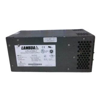
Summary of Contents for TDK-Lambda LZS-A1000-2
- Page 13 LZS-A1000-2 POWER SUPPLY Installation, Operation, and Maintenance Manual IM-LZSA1000-2 January 2022 Version H...
-
Page 14: Table Of Contents
LZS-A1000-2 Power Supply Table of Contents 1) Safety and Recommended Practices General safety instructions Safety Agency Approvals 2) RATINGS AND SPECIFICATIONS 3) FEATURES 4) GUIDE TO APPLICATION Safety Notice Input Voltage Output Voltage Overvoltage Protection Circuit Adjustment Overtemperature and Overvoltage Shutdown... -
Page 15: Safety And Recommended Practices
LZS-A1000-2 Power Supply 1 Safety and Recommended Practices 8. Openings in the product case are designed for ventilation and must not be 1.1 General Safety Instructions obstructed when the product is installed and/ This power supply is a switch mode power operated. -
Page 16: Ratings And Specifications
LZS-A1000-2 Power Supply Emissions AC Line Conducted Emissions EN55022/EN55011 (0.15-30 MHz) Class B Radiated RF Emissions EN55022/EN55011 30-1000 MHz Class B Powerline Harmonics EN61000-3-2 Class A Limits Powerline Fluctuation/Flicker EN61000-3-3 Complies Immunity Electrostatic Discharge IEC61000-4-2 +/-8 kV Air +/-6 kV Contact... - Page 17 LZS-A1000-2 Power Supply Input Specifications Units LZS-A1000-2 Input Voltage Range 85-265 (47-440Hz) Single Phase 100-380 Input Current (RMS, maximum) 15 RMS Inrush Current (Peak, at cold start) 30A /110VAC; 40A /220VAC Power Factor Harmonics EN61000-3-2 Compliant Power Factor (at max output power) 0.98 typical @ 85VAC...
-
Page 18: Features
LZS-A1000-2 Power Supply Operating Modes Series Operation Yes (see Fig. 7) Parallel Operation Two or more identical units (see Fig. 6). (Use of D. con. terminal 5 will (with current sharing) provide current sharing to within 10% nominal of rated 60°C current.) *Not backward compatible with the LZS-1000-2 power supply. - Page 19 LZS-A1000-2 Power Supply Protection Features Output Voltage Range 10-15.75V Nominal Factory Set Point Overvoltage Protection (adjustable) 12-19V (Factory set to 17V) Overcurrent Protection Factory set to 110% min. and 130% max. Thermal Protection Self-resetting thermostat.* Fusing Internal Isolation Voltages 4242 VDC, Input to Output...
-
Page 20: Guide To Application
LZS-A1000-2 Power Supply 4. GUIDE TO APPLICATION 4.1 SAFETY NOTICE Dangerous voltages exist in this equipment. Observe the usual safety precautions when operat- ing, wiring, or servicing to reduce the risk of shock or injury. 4.2 INPUT VOLTAGE See Table 3 on page 4. -
Page 21: Figures
LZS-A1000-2 Power Supply 5. Figures Figure 1 - PIN Assignments for TB201 and chassis mounted “D” connector Page. 08 401 Mile of Cars Way, Suite 325 • National City, CA 92154 • 1-800-LAMBDA-4 Revision H : January 2022... - Page 22 LZS-A1000-2 Power Supply LS = Local Sense S = Remote Sense Figure 2 - Typical Local Sense Connection LS = Local Sense S = Remote Sense Figure 3 - Typical Remote Sense Connection Page. 9 401 Mile of Cars Way, Suite 325 • National City, CA 92154 • 1-800-LAMBDA-4...
- Page 23 LZS-A1000-2 Power Supply LS = Local Sense S = Remote Sense Figure 4 - Remote Voltage Control with an External Programming Resistor or Voltage Source (Local Sensing) LS = Local Sense S = Remote Sense Figure 5 - Remote Voltage Control with an External Programming Resistor or Voltage Source (Remote Sensing) Page.
- Page 24 LZS-A1000-2 Power Supply Figure 6 - Parallel Operation Page. 11 401 Mile of Cars Way, Suite 325 • National City, CA 92154 • 1-800-LAMBDA-4 Revision H : January 2022...
- Page 25 LZS-A1000-2 Power Supply Figure 7 - Series Operation Page. 12 401 Mile of Cars Way, Suite 325 • National City, CA 92154 • 1-800-LAMBDA-4 Revision H : January 2022...
- Page 26 LZS-A1000-2 Power Supply Figure 8 - Outline Drawing Page. 13 401 Mile of Cars Way, Suite 325 • National City, CA 92154 • 1-800-LAMBDA-4 Revision H : January 2022...
- Page 27 LZS-A1000-2 Power Supply Figure 9 - Remote Output On/Off Control Figure 10 - Input Good, Inverter Good & Output Good Signals Page. 14 401 Mile of Cars Way, Suite 325 • National City, CA 92154 • 1-800-LAMBDA-4 Revision H : January 2022...


Need help?
Do you have a question about the LZS-A1000-2 and is the answer not in the manual?
Questions and answers