
Subscribe to Our Youtube Channel
Related Manuals for PMA KS 98


Summary of Contents for PMA KS 98
- Page 1 KS 98 and KS 98plus Multi-function unit KS98 S98K & 98KS TS.D TE.D TS.H TE.H LimL TS.Mi TE.Mi LimH 8KS9 Functional description 9499 040 50611 Valid from: 8474...
- Page 2 All rights reserved. No part of this document may be reproduced or published in any form or by any means without prior written permission from the copyright owner. A publication of: PMA Prozeß- und Maschinen-Automation GmbH P.O.Box 310 229 D-34058 Kassel Germany...
-
Page 3: Table Of Contents
Content 1. Description ..........7 Construction . - Page 4 11. Trigonometric functions ........39 11.1 SIN (sinus function) .
- Page 5 RM_DMS strain gauge module ........126 20. KS 98+ -KS98+ cross communication......129 20.1...
- Page 6 27. Additional functions ........221 27.1 LED (LED display) .
-
Page 7: Description
Additionally, the introduction of a CANopen interface completes the basic version of KS98 multifunction unit by local I/O extensibility by means of the PMA RM 200 modular I/O system connection of PMA KS800 / KS816 multiple-channel temperature controllers with CANopren interface... - Page 8 Description 9499 040 50611 Construction...
-
Page 9: Important Technical Data
Important technical data 9499 040 50611 Important technical data Analog inputs r sections 3 and 6.9 INP 1: universal input, configurable for thermocouples, resistance thermometers, tem perature difference, resistance transducers, DC current and DC voltage INP 3 and INP 4 (option C): DC current, INP 5: DC current and DC voltage INP 6: resistance transducer and DC current... - Page 10 Important technical data 9499 040 50611 Further external in- and outputs...
-
Page 11: Versions
Versions 9499 040 50611 Versions Order no. 9 4 0 7 - 9 standard Basic unit with integrated supply voltage KS98+ with CANopen I/O 90...250 V AC with 4 relays Power supply and 90...250 V AC with 2 relays + 2 current outputs process outputs 24 V UC with 4 relays 24 V UC with 2 relays + 2 current outputs... - Page 12 Versions 9499 040 50611 I/O-modules - for units with modular option c basic card...
-
Page 13: Front View
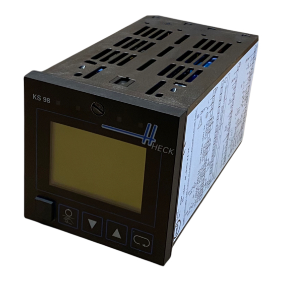
Front view 9499 040 50611 Front view LED 3 e.g. alarm 1 LED 2 e.g. cooling LED 4 e.g. alarm 2 LED 1 e.g. heating Locking screw Display e.g. trend Selector key Increment key (z) PC interface Decrement key (u) Manual/automatic key Locking screw: locks the controller module in the housing. - Page 14 Front view 9499 040 50611...
-
Page 15: Mounting
Mounting 9499 040 50611 Mounting Mount the unit with min. 2 fixing clamps (diagonally at top and bottom). Protection type IP65: use 4 fixing clamps. Insert the instrument module firmly and block it using the locking screw. S.I.L. switch S: its switching status is signalled by function STATUS and can be used in the engineering. After delivery, the switch is open. - Page 16 Mounting 9499 040 50611...
-
Page 17: Electrical Connections
Electrical connections 9499 040 50611 Electrical connections Safety hints Following the enclosed safety hints 9499 047 07101 is indispensable! The instrument insulation meets standard EN 61 010-1 (VDE 0411-1) with contamination degree 2, overvoltage category III, operating voltage range 300 V and protection class I. - Page 18 Electrical connections 9499 040 50611 In measuring and signal circuits, the max. potential against ground may be 50 Veff, Between power supply circuits, the max. potential may be 250 Veff. di (-) di1 (+) di2 (+) + Volt OUT5 + mA INP5 _ Volt / mA oder...
-
Page 19: Analog Inputs (R Connecting Diagram)
Electrical connections 9499 040 50611 Analog inputs (r connecting diagram) Thermocouples (a) No lead resistance adjustment is necessary. Internal temperature compensation: the compensating lead must be taken up to the instrument terminals. In AINP1 STK = int.TC must be configured. External temperature compensation: use a separate cold-junction reference with fixed reference temperature. -
Page 20: Versions With Integrated Supply Voltage
Electrical connections 9499 040 50611 Versions with integrated supply voltage The potential-free supply voltage can energize a 2-wire transmitter or max. 4 control inputs. The output connections can be selected with 3 S.I.L. switches: Ü Ö Connections Remarks Only available, if INP1 is configured for current or thermocouple 14(+) 12 (-) T open closed... -
Page 21: Menu
Menu 9499 040 50611 Menu The instrument operation is menu-guided. Distinction between complete dialogue and short-form dialogue is made. In the com- plete dialogue, the main menu with its sub-menus is shown so that all permitted settings are selectable. In the short-form dia- logue, the main menu is switched off so that accidental access is prevented. -
Page 22: Complete Dialogue
Menu 9499 040 50611 Complete dialogue A main menu for selecting the sub-menus, which can be used for selecting an instrument and application-dependent number of pages. Sub-menu Page contents The operating pages of VWERT, VPARA, VBAR, VTREND, APROG, DPROG, CONTR and Level 1 data CONTR+ are shown: display and adjustment of operating values. -
Page 23: Language Selection
Menu 9499 040 50611 Language selection English: mark Allgemeine Daten r Gerätedaten r Sprach = deutsch. Press M: deutsch blinks. Press I: english blinks. Press M: Main menu is displayed. German: Mark Miscellaneous r Device data r Langu. = english. Press M: english blinks. -
Page 24: Calibrating
Menu 9499 040 50611 Calibrating Select (ID) and open (M) Miscellaneous r Calibration. Select the bottommost line by pressing I (in- verted display, e.g. Quit). Then continue as follows: Transducer input (INP1 or INP6) 2 Resistance thermometer in difference (INP1) Calibrating the transducer start and end: Calibrating the lead resistance effect: Ü... -
Page 25: Maintenance
Maintenance 9499 040 50611 Maintenance Behaviour in case of trouble The unit is maintenance-free. In case of trouble, the following points must be checked. The unit is in on-line mode. The supply voltage is connected correctly with correct voltage and frequency. All connections are in correct condition. - Page 26 Maintenance 9499 040 50611 Further information...
-
Page 27: Scaling And Calculating Functions
Scaling and calculating functions 9499 040 50611 Scaling and calculating functions ABSV ( absolute value ) × + The absolute value of a number is the number without polarity sign. Input variable x1 is multiplied by factor a (parameter). Now, constant a0 is added. The absolute value of the result- ing value is formed and output at y1. -
Page 28: Adsu ( Addition/Subtraction )
Scaling and calculating functions 9499 040 50611 ADSU ( addition/subtraction ) = × + × + × + × Input variables x1...x4 are multiplied by factors a...d. Constant y0 is added to the sum of evaluated inputs. Value “0" is assigned automatically to unused inputs. Parameter Description Range... -
Page 29: Mudi ( Multiplication / Division )
Scaling and calculating functions 9499 040 50611 MUDI ( Multiplication / division ) × × + × × + × Input variables x1...x3 are multiplied by factors a, b, c. The relevant constants a0, b0, c0 are added. The out- put variable corresponds to the product. -
Page 30: Sqrt ( Square Root Function )
Scaling and calculating functions 9499 040 50611 SQRT ( square root function ) × + Constant a0 is added to input variable x1 multiplied by a. The result is subjected to square root extraction. Constant y0 is added to the result of square root extraction. If the expression under the root is negative, the square root expression is set to 0. -
Page 31: Scal ( Scaling )
Scaling and calculating functions 9499 040 50611 SCAL ( scaling ) × + Input variable x1 is multiplied by factor a and added to constant a0. The result (a w x1 + a0) is set to the power Exp. If x1 is not used, this is interpreted as x1=0. With Exp = 0 SCAL outputs 1. Parameter Description Range... -
Page 32: 10Exp (10S Exponent)
Scaling and calculating functions 9499 040 50611 10EXP (10s exponent) Input value x1 is calculated according to formula y and output at the y1 output. An unwired x1 is interpreted as x1 = 0 (in this case y1 is 1). If the value at input x1 is higher than 36,7, an overflow may occur. -
Page 33: Eexp (E-Function)
Scaling and calculating functions 9499 040 50611 EEXP (e-function) The e-function is calculated. If input signal x1 is higher than 85, there may be an overflow. In this case, y1 = 1,5 is output rather than form- ing the power. If x1 is not wired, this is interpreted as x1 = 0 and thus as y1 = 1. -
Page 34: Ln (Natural Logarithm)
Scaling and calculating functions 9499 040 50611 LN (natural logarithm) The natural logarithm of input variable x1 is formed. The basis of natural logarithms is constant e (2,71828182845904). If x1 is not wired, this is interpreted as x1 = 1. In this case y1 is 0. With a negative input variable x1, y1 = -1,5 is set. -
Page 35: Lg10 (10S Logarithm)
Scaling and calculating functions 9499 040 50611 LG10 (10s logarithm) The common logarithm of input variable x1 is formed. LG10 provided the logarithm of a number to base 10. If x1 is not wired, this is interpreted as x1 = 1. In this case, y1 is 0. With a negative input variable x1, y1 = -1,5 is set. - Page 36 Scaling and calculating functions 9499 040 50611 LG10 (10s logarithm)
-
Page 37: Non-Linear Functions
Non-linear functions 9499 040 50611 Non-linear functions 10.1 GAP (dead band) bei x1 < L bei x1 = L...H bei x1 > H The range of the dead band is adjusted with parameters Low (lower limit) and High (upper limit). If input value x1 is within the dead band (Low ß... -
Page 38: Char (Function Generator)
Non-linear functions 9499 040 50611 10.2 CHAR (function generator) With max. 11 adjustable value pairs, non-linear functions can be simulated or linearized. Each value pair comprises input x(1) and output y(1). The number of value pairs is determined using configuration parameter Seg (number of segments +1 corre- sponds to the number of value pairs). -
Page 39: Trigonometric Functions
Trigonometric functions 9499 040 50611 Trigonometric functions 11.1 SIN (sinus function) The function provides the sinus of the input value, i.e. x1 is the angle the sinus of which is calculated. Parameter Select is used to adjust, if the angle is provided in degree of angle [°] or in radian. The calculation clarity can be reached by limiting the input signal (e.g. -
Page 40: Cos (Cosinus Function)
Trigonometric functions 9499 040 50611 11.2 COS (cosinus function) The function provides the cosinus of the input value, i.e. x1 is the angle the cosinus of which is calculated. Parameter Select is used to adjust, if the angle is provided in degree of angle [°] or in radian. Calculation clarity can be reached by limiting the input signal (e.g. -
Page 41: Tan (Tangent Function)
Trigonometric functions 9499 040 50611 11.3 TAN (tangent function) - °< <+ ° < < valid for x The function provides the tangent of the input value, i.e. x1 is the angle the tangent of which is calculated. Parameter Select is used to adjust, if the angle is provided in degree of angle [°] or in radian. ó... -
Page 42: Cot (Cotangent Function)
Trigonometric functions 9499 040 50611 11.4 COT (cotangent function) < < ° < < p valid for x 180 0 The function provides the cotangent of the input value, i.e. x1 is the angle the cotangent of which is calculated. Pa- rameter Select is used to adjust, if the angle is provided in degree of angle [°] or in radian. -
Page 43: Arcsin (Arcus Sinus Function)
Trigonometric functions 9499 040 50611 11.5 ARCSIN (arcus sinus function) arcsin - £ £+ valid for x The function provides the arcus sinus of the input value, i.e. x1 is the angle the arcus sinus of which is calculated. Pa- rameter Select is used to adjust, if the angle is provided in degree of angle [°] or in radian. -
Page 44: Arccos (Arcus Cosinus Function)
Trigonometric functions 9499 040 50611 11.6 ARCCOS (arcus cosinus function) arccos 1) - £ £+ valid for x The function provides the arcus sinus of the input value, i.e. x1 is the angle the arcus sinus of which is calculated. Pa- rameter Select is used to adjust, if the angle is provided in degree of angle [°] or in radian. -
Page 45: Arctan (Arcus Tangent Function)
Trigonometric functions 9499 040 50611 11.7 ARCTAN (arcus tangent function) arctan The function provides the arcus tangent of the input value, i.e. x1 is the angle the arcus tangent of which is calcu- lated. Parameter Select is used to adjust, if the angle is provided in degree of angle [°] or in radian. The calculation is output either as degree of angle [-90°... -
Page 46: Arccot (Arcus Cotangent Function)
Trigonometric functions 9499 040 50611 11.8 ARCCOT (arcus cotangent function) arccot The function provides the arcus cotangent of the input value, i.e. x1 is the angle the arcus cotangent of which is cal- culated. Parameter Select is used to adjust, if the angle is provided in degree of angle [°] or in radian. The calculation is output in degree of angle [0°... -
Page 47: Logic Functions
Logic functions 9499 040 50611 Logic functions 12.1 AND (AND gate) d AND d AND d AND d Logic function AND combines inputs d1...d4 according to the truth table given below. Unused inputs are interpreted as logic 1. not z2 AND (AND gate) -
Page 48: Not (Inverter)
Logic functions 9499 040 50611 12.2 NOT (inverter) Logic input signal d1 is output invertedly at y1. If d1 is not wired, this is interpreted as logic 0. not z1 NOT (inverter) -
Page 49: Or (Or Gate)
Logic functions 9499 040 50611 12.3 OR (OR gate) d OR d OR d OR d Logic function OR combines inputs d1...d4 according to the truth table given below. Unused inputs are interpreted as logic 0. not z1 OR (OR gate) -
Page 50: Bounce (Debouncer)
Logic functions 9499 040 50611 12.4 BOUNCE (debouncer) This function is used for de-bouncing a logic signal. The change of input signal d1 is transferred to output z1 only, when it remained constant for the time adjusted in parameter Delay. The time-out accuracy is dependent of the sam- pling interval assigned to the function. -
Page 51: Exor (Exclusive Or Gate)
Logic functions 9499 040 50611 12.5 EXOR (exclusive OR gate) d EXOR d Logic inputs d1 and d2 are combined into z1 according to the truth table given below. Unused inputs are inter- preted as logic 0. Output z1 is 0, when the two inputs are equal (both 0 or both 1). EXOR (exclusive OR gate) -
Page 52: Flip (D Flipflop)
Logic functions 9499 040 50611 12.6 FLIP (D flipflop) The digital signal status at static input signal is transferred to output z1 when the signal at clock input clock changes from 0 to 1 (positive flank), and when input reset is logic 0. With reset = 1, output z1 is forced to 0 independent of inputs signal and clock. -
Page 53: Mono (Monoflop)
Logic functions 9499 040 50611 12.7 MONO (monoflop) The function generates a positive pulse of length Ti at output z1, when a positive flank at trigger input d1 is detected. It generates a positive pulse of length Ti at output z3, when a negative flank at trigger input d2 is detected. Pulse duration Ti is adjusted either as parameter Ti1 or read in via inputs Ti1. - Page 54 Logic functions 9499 040 50611 Parameters: Parameter Description Range Default Para.Ti1 Source of pulse duration at z1 Parameter Ti1 Mode 1 Input Ti1 Input Ti1 Para.Ti2 Source of pulse duration at z3 Parameter Ti2 Mode 2 Input Ti2 Input Ti2 Duration of the pulse generated by d1,when Mode 1 = Para.Ti1 is entered.
-
Page 55: Step (Step Function For Sequencing)
Logic functions 9499 040 50611 12.8 STEP (step function for sequencing) The STEP function realizes the individual steps for sequencing. The function starts with RESET at step 1 and remains at this step, until the relevant condition input d or the skip input is set from 0 to 1. - Page 56 Logic functions 9499 040 50611 Inputs/outputs Digital inputs d1...d10 Condition inputs for switching over to the next step With input reset = 1, output Step is set to 1 (only with individual function or at the first step of reset = the Casc input is set.
-
Page 57: Time1 (Timer)
Logic functions 9499 040 50611 12.9 TIME1 (timer) The function outputs the change of signal status at d1 with a delay at z1. The delay time can be adjusted separately for each change direction of the signal status! (positive and negative flank). With change from 0 to 1 at input d1, output z1 is switched to 1 with a delay of time T1. - Page 58 Logic functions 9499 040 50611 Configuration: Configuration Description Range Default Parameters parameters T1 and T2 Mode Source of delay times Inputs Inputs T1 and T2 Example with different delay time T1 and T2 TIME1 (timer)
-
Page 59: Signal Converters
Signal converters 9499 040 50611 Signal converters 13.1 AOCTET data type conversion Function AOCTET converts an analog value (X1) into the individual bytes (Ooct1-4) of a data type as used e.g. for trans- mission via the CAN bus ( see CPREAD / CPWRIT ). In the CAN notation, the bytes are transmitted in Intel format. Un- less connected instruments are in compliance with this notation, word or bytewise echange of the bytes may be necessary. - Page 60 Signal converters 9499 040 50611 Engineering examples SDO for data reading This example shows a possibility for data reading via an SDO access. Node address, data type, index and sub-index can be adjusted on an operating page. On the first line, a trigger bit which is reset by the following “ready” signal of the SDO block can be set.
- Page 61 Signal converters 9499 040 50611 SDO for data read/write with node guarding and set operational Enforce NMT command „set operational“ Disable trigger by means of valid output (on AND) In this engineering example for data write and read via SDOs, a trigger can be set automatically when changing a value to be transmitted, or manually via the first line of the operating page.
- Page 62 Signal converters 9499 040 50611 Generating an SDO command sequence Engineering example SDO-SEQ.EDG shows the generation of an endless SDO command sequence. The values for D-type, sub-index, index and value are stored in the recipe blocks. The counter ( COUN ) counts from 1 to 15 continu- ously.
- Page 63 Signal converters 9499 040 50611 An extended engineering for advanced users SDO-SEQ2.EDG shows further functions and possibilities of KS98 engineerings in conjunction with command sequences. This partial engineering shows the possibility of access to SDO block parameters via an operating page. AOCTET data type conversion...
- Page 64 Signal converters 9499 040 50611 This partial function monitors the change of settings on the operating page and starts a pulse (value change) for stor- age in the recipe blocks. Command triggering is subject to various conditions: when reading, after changing during manual mode and cyclically in automatic mode.
-
Page 65: Abin (Analog I Binary Conversion)
Signal converters 9499 040 50611 ABIN (analog i binary conversion) 13.2 Analog input variable x1 is converted into a binary number, a BCD number or a selection “1 out of 8". Thereby, x1 is always rounded off (down for values < 0,5, up for values ? 0,5). Simultaneously, binary input values d1...d8 ( considered as a binary number or a BCD number) can be converted into an analog output variable. - Page 66 Signal converters 9499 040 50611 Converting a BCD number into an analog value BCD input values at inputs d1...d4 and d5...d8 are converted into a floating point number and available at output With a BCD number > 9 at inputs d1...d4 or d5...d8, output variable y1 is limited to 9. Out of the range, the output allocation is: Output y1 =...
-
Page 67: Trunc (Integer Portion)
Signal converters 9499 040 50611 13.3 TRUNC (integer portion) INT x The function provides the integer portion (integer) of input variable x1 without rounding off at output y1. Example: x1 = 1,7 y1 = 1,0 x1 = -1,7 y1 = -1,0 Inputs/outputs Analog input Input variable to be handled... -
Page 68: Puls (Analog Pulse Conversion)
Signal converters 9499 040 50611 13.4 PULS (analog pulse conversion) Number of pulses per hour × Parameter x0 = n Puls h Parameter x100 = Analog input x1 = Input variable x1 is converted into a number of pulses per hour. Parameter Puls/h is used for selecting the maximum number of pulses at x1 ? x100. - Page 69 Signal converters 9499 040 50611 Inputs/outputs Analog input Input variable to be converted Digital output Pulse output No configuration parameters Parameters: Parameter Description Range Default Span start (0 %) -29 999...999 999 x100 Span end (100 %) -29 999...999 999 Puls/h Number of output pulses per hour for x1 ? x100.
-
Page 70: Coun (Up/Down Counter)
Signal converters 9499 040 50611 13.5 COUN (up/down counter) ‘COUN’ is an up/down counter and counts the events at input up or down, which are available at the up or down input for at least the duration of the time group in which the function runs. reset preset Mode... - Page 71 Signal converters 9499 040 50611 Function up counter: At each positive flank (0 r 1) at input up, output Count is increased by 1, until the max. limit is reached. Carry output carry is set to 0 for the duration of the applied pulse. With the next pulse, output Count returns to the min. value and continues counting with the next pulses.
-
Page 72: Mean (Mean Value Formation)
Signal converters 9499 040 50611 13.6 MEAN (mean value formation) General Function MEAN forms the floating, arithmetic mean value of the number (ValNo) of the values detected last at input x1 for output at output y1. The interval between the individual samplings (interval) is adjustable with Sample and Unit. Unit is used to specify the measurement interval (sec = seconds, min = minutes or h = hours). - Page 73 Signal converters 9499 040 50611 reset Analog input Mean goes to value 0 for the duration of the applied reset signal. The stored values are deleted. Example: ValNo = 5 output Mean at reset: Detection that no valid values are available is made. Value 0 is output at output y1. ValNo = 5 1st sample after reset: Detection that only one valid valid value is available is made.
- Page 74 Signal converters 9499 040 50611 MEAN (mean value formation)
-
Page 75: Time Functions
Time functions 9499 040 50611 Time functions 14.1 LEAD ( differentiator ) The differentiator forms the difference quotient according to equation: sampling interval x1(t) instantaneous x1 × + × time constant x1(t-ts) previous x1 gain y1(t) instantaneous y1 y0 output offset y1(t-ts) previous y1 <1 ( differentiation constant ) ×... - Page 76 Time functions 9499 040 50611 Step response: After a step change of input variable x1 by {x =xt-x(t-ts), the output changes to maximum value y max. = × × and decays to 0 according to function × × y n ts ( .
-
Page 77: Inte ( Integrator )
Time functions 9499 040 50611 14.2 INTE ( integrator ) The integrator forms the integral according to equation: sampling interval x1(t) instantaneous x1 Integration constant y1(t) y1 after t=n*ts + × Number of calculation cycles y1(t-ts) previous y1 Input offset The complex transfer function is: ×... - Page 78 Time functions 9499 040 50611 Digital outputs = 1 exceeded with max. limiting = 1 exceeded with min. limiting Analog output = × Integrator output after elapse of integration t n ts Parameters: Parameter Description Range Default Time constant in s 0.1...999 999 Constant -29 999...999 999...
-
Page 79: Lag1 ( Filter )
Time functions 9499 040 50611 14.3 LAG1 ( filter ) Dependent of control input reset, input variable x1 is passed on to output y1 with delay (reset= 0) or without delay (re- set = 1). Delay is according to a 1st order e-function ( 1st order low pass ) with time constant T(s). The output variable for reset= 0 is calculated according to the following equation: ts sampling interval x1 (t) -
Page 80: Dela1 ( Delay Time )
Time functions 9499 040 50611 14.4 DELA1 ( delay time ) If the clock input is not wired, the function calculates y1(t) = x1 (t-n • ts). ( ts = sampling interval, Delay = delay factor n) Unless clock input clock is wired, the following is applicable: input variable x1 is output with a delay by n times the ×... -
Page 81: Dela2 ( Delay Time )
Time functions 9499 040 50611 14.5 DELA2 ( delay time ) The function provides calculation x t Td Input variable x1 is output at y1 with delay by time Td. The accuracy Td is dependent of the time group ( sampling inter- val ts) , to which the function is assigned. -
Page 82: Filt ( Filter With Tolerance Band )
Time functions 9499 040 50611 14.6 FILT ( filter with tolerance band ) <<= d is: The complex transfer function of the filter within a tolerance band around the last output value ( | ( )= + × With a difference higher than Diff or reset = 1 between input x1 and output y2, the filter stage is switched off and the output follows the input directly. -
Page 83: Timer ( Timer )
Time functions 9499 040 50611 14.7 TIMER ( timer ) is switched on at absolute time TS The function timer can only be used with real-time clock (9407-9xx-2xxx). Output z and switched off again after TE. This switching operation can be unique or cyclical (parameter adjustment). Output Week-D indicates the actual weekday (0...6 = Su...Sa) . -
Page 84: Timer2 ( Timer )
Time functions 9499 040 50611 14.8 TIMER2 ( timer ) The function timer2 can only be used with real-time clock (9407-9xx-2xxx).With a positive flank at start, TIMER2 is started and output z1 is switched to 1 after elapse of time TS and reset to 0 after elapse of time TE. Example: TS.D = 2, TS.H = 1, TS.Mi = 30 TE.D = 0, TE.H = 2, TE.Mi = 2 After the change from 0 to 1 at input start, output z1 is set to 1 after 2 days, 1 hour and 30 seconds and reset to... -
Page 85: Selecting And Storage
Selecting and storage 9499 040 50611 Selecting and storage 15.1 EXTR ( extreme value selection ) y1>y2>y3 MaxNo MidNo MinNo Analog inputs x1, x2 and x3 are sorted according to their instantaneous values and provided at outputs Max, Mid and Min. Input value output is at Max for the highest one, at Mid for the medium one and at Min for the smallest one. -
Page 86: Peak ( Peak Value Memory )
Selecting and storage 9499 040 50611 15.2 PEAK ( peak value memory ) are determined, stored and output at Max and Min. With Maximum input value x and minimum input value x the stop input set to 1, the extreme values determined last remain unchanged. If the reset input is set to 1, the extreme value memory and any applied stop command are cancelled. -
Page 87: Trst ( Hold Amplifier )
Selecting and storage 9499 040 50611 15.3 TRST ( hold amplifier ) With control input hold set to 1, instantaneous input value x1 is stored and output at y1. With control input hold set to 0, output y1 follows input value x1. The function has a ‘memory’. -
Page 88: Selc ( Constant Selection )
Selecting and storage 9499 040 50611 15.4 SELC ( Constant selection ) Dependent of control signal d1, the four preset parameters of group 1 or of group 2 are output. Inputs/outputs Digital input Selecting the constant group (0 = group 1; 1= group 2) Analog outputs d1= 0 = group 1 d1=1 = group 2... -
Page 89: Selp ( Parameter Selection )
Selecting and storage 9499 040 50611 15.5 SELP ( parameter selection ) Dependent of control signals d1 and d2, either one of the three preset parameters C1, C2, C3 or input variable x1 is connected with output y1. Unused inputs are interpreted as 0 or logic 0. Inputs/outputs Digital inputs 1st digital input for parameter selection... -
Page 90: Selv1 ( Variable Selection )
Selecting and storage 9499 040 50611 15.6 SELV1 ( variable selection ) Dependent of control signals d1 and d2, one of four inputs x1...x4 is connected with output y1. Unused inputs are interpreted as 0 or logic 0. Inputs/outputs Digital inputs 1st digital input for parameter selection 2nd digital input for parameter selection Analog inputs... -
Page 91: Sout ( Selection Of Output )
Selecting and storage 9499 040 50611 15.7 SOUT ( Selection of output ) Dependent of control signals d1 and d2,, input variable x1is connected to one of outputs y1, y2, y3 or y4. Unused inputs are interpreted as 0 or logic 0. Inputs/outputs Digital inputs 1st digital input for output selection... -
Page 92: Rezept ( Recipe Management )
Selecting and storage 9499 040 50611 15.8 REZEPT ( recipe management ) The function has 5 groups (recipe blocks) each with 4 memory locations. The recipes can be written via parameter set- ting and analog inputs. The function parameters are stored in EEPROM with back-up. Selection which recipe block is output at y1...y4 is determined by the value applied to input SetNo. - Page 93 Selecting and storage 9499 040 50611 Inputs/outputs Digital inputs This input reacts only on a positive flank, i.e. on a change from 0 to 1. With this flank, input values store x1...x4 are stored in the recipe block selected with SetNo. The values are stored in RAM and in dynamic EEPROM.
-
Page 94: 2Of3 ( 2-Out-Of-3 Selection With Mean Value Formation )
Selecting and storage 9499 040 50611 15.9 2OF3 ( 2-out-of-3 selection with mean value formation ) Function 2OF3 forms the arithmetic mean value of input variables x1, x2 and x3. The difference of x1, x2 and x3 is formed and compared with parameter Diff. Inputs the value of which exceeds this limit value are not used for mean value formation. - Page 95 Selecting and storage 9499 040 50611 Inputs/outputs Digital inputs fail1 Error message for input x1. With fail1 = 1, input x1 is not taken into account for mean value formation. fail2 Error message for input x2. With fail2 = 1, input x2 is not taken into account for mean value formation. fail3 Error message for input x3.
-
Page 96: Selv2 ( Cascadable Selection Of Variables )
Selecting and storage 9499 040 50611 15.10 SELV2 ( cascadable selection of variables ) Dependent of input Select,, one of the four inputs x1...x4 is connected with output y1. Unused inputs are interpreted as 0. Output Casc = input Select -3. The function can be cascaded as shown in the example given below. -
Page 97: Limit Value Signalling And Limiting
Limit value signalling and limiting 9499 040 50611 Limit value signalling and limiting 16.1 ALLP ( alarm and limiting with fixed limits ) Limiting at H1 Signal limiting: Parameter L1 determines the minimum, H1 the maxi- mum limiting. y1 is limited to the range between L1 and H1. - Page 98 Limit value signalling and limiting 9499 040 50611 Inputs/outputs Analog input Input value to be monitored Digital outputs Low alarm 1 - becomes logic 1, if x1 < L1 Low alarm 2 - becomes logic 1, if x1 < L2 High alarm 1 - becomes logic 1, if x1 <H1 High alarm 2 - becomes logic 1, if x1 <H2 Analog output...
-
Page 99: Allv ( Alarm And Limiting With Variable Limits )
Limit value signalling and limiting 9499 040 50611 16.2 ALLV ( alarm and limiting with variable limits ) Limiting at H1 Signal limiting: Analog input H1determines the maximum limiting, L1 deter- mines the minimum limiting. y1 is limited to the range be- tween L1 and H1 (L1 ß... - Page 100 Limit value signalling and limiting 9499 040 50611 Inputs/outputs Analog inputs Input value to be monitored High alarm 1 Low alarm 1 Digital outputs Low alarm 1 - is logic 1 with x1 <L1 Low alarm 2 - is logic 1 with x1 <L2 High alarm 1 - is logic 1 with x1 <H1 High alarm 2 - is logic 1 with x1 <H2 Analog output...
-
Page 101: Equal ( Comparison )
Limit value signalling and limiting 9499 040 50611 16.3 EQUAL ( comparison ) The function checks the two analog input values x1 and x2 for equality. The values are equal, if the amount of their difference is smaller than oder equal to the preset tolerance. Comparison conditions x2 + Diff <... -
Page 102: Velo ( Rate-Of-Change Limiting)
Limit value signalling and limiting 9499 040 50611 16.4 VELO ( rate-of-change limiting) The function passes input variable x1 to output y1 and limits its rate of change dx1/dt to a positive and negative gradi- ent. The gradients can be adjusted either as parameter GrX+ and Grx- or preset at analog inputs GrX+ and Grx-. Switch-over between the gradient sources is by parameter Mode+ for the positive gradient and by Mode- for the negative gradient. -
Page 103: Limit ( Multiple Alarm )
Limit value signalling and limiting 9499 040 50611 16.5 LIMIT ( multiple alarm ) The function checks input variable x1 for 8 alarm values L1...L 8. Dependent of configuration by Mode 1 ... Mode 8, the relevant alarm value is evaluated as MAX or MIN alarm. With MAX alarm configuration, the alarm is triggered when the input signal is higher than the alarm value and finished when it is lower than ( alarm value - hysteresis Xsd ). -
Page 104: Alarm ( Alarm Processing )
Limit value signalling and limiting 9499 040 50611 16.6 ALARM ( alarm processing ) x1 is checked for a lower and an upper alarm value. Additionally, digital alarm input fail can be used. Configura- tion parameter Fnc can be used to select which signal shall be monitored (x1, x1 + fail or fail). With input stop = 1, alarms (fail and x1) are suppressed. -
Page 105: Vwert ( Display / Definition Of Process Values )
Visualization 9499 040 50611 Visualization 17.1 VWERT ( display / definition of process values ) Disp 1 Mode 1 Disp 2 Mode 2 Disp 3 Mode 3 Disp 4 Mode 4 Disp 5 Mode 5 Disp 6 z6 Y6 Mode 6 store lock hide... - Page 106 Visualization 9499 040 50611 Inputs/outputs Digital inputs: hide Display suppression (with hide = 1 the page is not displayed in the operation. lock Adjustment locking (with lock = 1 the values are not adjustable by means of keys ID). d1 ... d6 Process statuses to be displayed.
-
Page 107: Vbar ( Bargraph Display )
Visualization 9499 040 50611 17.2 VBAR ( bargraph display ) Disp 1 Disp 2 0 X3 mid X3 100 X4 mid X4 100 lock hide General This function permits the display of 2 analog input signals as bargraphs, and of 2 analog input signals as numeric val- ues. - Page 108 Visualization 9499 040 50611 Parameter and configuration data Parameter Description Range Default Y1 / Y2 Start values at power-on -29999...999 999 Configuration Description Values Default disp+adj Function of display x1 / x2, value adjustable Disp1 display numeric only display x1 / x2 Disp2 display 1 and x1 / x2 = empty...
-
Page 109: Vpara ( Parameter Operation )
Visualization 9499 040 50611 17.3 VPARA ( parameter operation ) Block1 Num1 Block2 Num2 Block3 Num3 Block4 Num4 Block5 Num5 Block6 Num6 store lock hide General Function VPARA provides an operating page which can be used for changing max. 6 parameters of other function blocks available in the engineering from the operating level. - Page 110 Visualization 9499 040 50611 Digital outputs: The outputs provide a status, which shows if the last storage of the values taken over from the z1 ... z6 inputs was successful (z1 ... z6 = 0). Errors may occur due to exceeded limits of the parameter value or due to non-existing parameters (z1 ...
-
Page 111: Vtrend ( Trend Display )
Visualization 9499 040 50611 17.4 VTREND ( trend display ) X 100 . . . sample disabl X-100 Unit Sample ready reset hide General Function VTREND collects 100 values of the analog input ‘x1‘ in a shift register and permits value display as a trend curve. - Page 112 Visualization 9499 040 50611 Text display and entry Changing the texts displayed in the unit is possible only in the engineering tool! Max. 16 characters can be entered into each text parameter. Trend curve The following values or texts are displayed: Ü...
-
Page 113: Communication
Communication 9499 040 50611 Communication ISO 1745 In total, max. 20 L1READ and L1WRIT functions can be configured (blocks 1...20 ), any combination of functions is pos- sible. Any number of data can be used in the functions. 18.1 L1READ ( read level1 data ) Interface Statusbyte1 6 5 4 3 2 1 0... -
Page 114: L1Writ ( Write Level1 Data )
Communication 9499 040 50611 18.2 L1WRIT ( write level1 data ) Interface Code 31 4 3 2 1 0 9 8 7 6 5 4 3 2 1 0 EEPROM Code 32 Code 33 Code 34 Code 35 Code 36 Code 37 Code 38 Code 39... -
Page 115: Dpread ( Read Level1 Data Via Profibus )
Communication 9499 040 50611 PROFIBUS Max. 4 functions DPREAD and DPWRIT can be configured (blocks 1...4 or 11...14 ). Any combination of functions is pos- sible. Any data can be used in the functions. 18.3 DPREAD ( read level1 data via PROFIBUS ) Interface Statusbyte1 7 6 5 4 3 2 1 0... -
Page 116: Dpwrit ( Write Level1 Data Via Profibus )
Communication 9499 040 50611 18.4 DPWRIT ( write level1 data via PROFIBUS ) Interface 7 6 5 4 3 2 1 0 b-err 7 6 5 4 3 2 1 0 p-err c-err d-err valid General Block numbers 11...14. The data of a PROFIBUS data channel are transmitted into the memory. Block number 11 trans- mits the data of channel 1, block number 12 transmits the data of channel 2, etc. -
Page 117: Ks98+ I/O Extensions With Canopen
KS98+ I/O extensions with CANopen The additional CANopen interface completes the func- tionality of the multifunction unit basic version by: local I/O extensibility using the PMA RM 200 modular I/O system. connection of the PMA multiple-channel temperature controllers with CANopen interface... -
Page 118: Rm 211, Rm212 And Rm213 Basic Modules
KS98+ I/O extensions with CANopen 9499 040 50611 19.1 RM 211, RM212 and RM213 basic modules +24 V +24V +24 V 0..20 0..20 IN 1 0..20 0..10 0..20 -10..10 0..20 Sense +24 V +24V +24V +24 V 0..20 0..20 0..10 0..20 IN 2 0..20... -
Page 119: C_Rm2X (Canopen Fieldbuscoupler Rm 201)
KS98+ I/O extensions with CANopen 9499 040 50611 19.2 C_RM2x (CANopen fieldbuscoupler RM 201) Coupler module RM201 is fitted with an interface to the CAN bus and plugs into the first slot. The other slots are provided for various I/O modules, which are polled cyclically via an internal bus. Outputs Analog Outputs Slot1... -
Page 120: Rm_Di (Rm 200 - (Digital Input Module)
KS98+ I/O extensions with CANopen 9499 040 50611 19.3 RM_DI (RM 200 - (digital input module) Function RM_DI handles the data from the connected digital input modules. Inputs and outputs Analog input Slotx Connection of one of the slot outputs of the RM200 node (C_RM2x) Digital outputs 1 = engineering error (several RM module functions at a 0 = no engineering error... -
Page 121: Rm_Do (Rm 200 - Digital Output Module)
KS98+ I/O extensions with CANopen 9499 040 50611 19.4 RM_DO (RM 200 - digital output module) Function RM_DO handles the data from connected digital output modules. Input and output modules Analog input Slotx Connection of one of the slot outputs of the RM200 node (C_RM2x) Digital inputs do 1 Set-points for digital inputs 1 to 8... -
Page 122: Rm_Ai (Rm200 - Analog Input Module)
KS98+ I/O extensions with CANopen RM_AI (RM200 - analog input module) 19.5 RM_AI (RM200 - analog input module) Function RM_AI handles the data from connected analog input modules. Inputs and outputs Analog input Slotx Connection of one of the slot outputs of the RM200 node (C_RM2x) Digital outputs et-err 0 = no engineering error detected... - Page 123 KS98+ I/O extensions with CANopen 9499 040 50611 Parameter and configuration data Configuration Description Range Default 0: RM221-0 = 4 x 0/4...20 mA 1: RM221-1 = 4 x -10/0...10 V 2: RM221-2 = 2 x 0/4...20 mA + 2 x -10/0...10 V 3: RM222-0 = 4 x 0/4...20 mA, TPS MTyp Module type...
-
Page 124: Potentiometer Connection And Calibration
KS98+ I/O extensions with CANopen Potentiometer connection and calibration 19.6 Potentiometer connection and calibration Connection: Modules RM 222-1 and RM222-2 are also suitable for connection of potentiometers. Max. two potentiometers can be connected to module RM222-2 and max. four potentiometers can be connected to module RM 222-1. -
Page 125: Rm_(Rm200 - Analog Output Module)
RM_(RM200 - analog output module) KS98+ I/O extensions with CANopen 19.7 RM_(RM200 - analog output module) Function RM_AO handles the data from connected analog output modules. Input and outputs Analog inputs Slotx Connection of one of the Slot outputs of the RM 200 node (C_RM2x) AO 1...AO 4 1st to 4th analog output signal Digital outputs et-err... -
Page 126: Rm_Dms Strain Gauge Module
RM_DMS strain gauge module KS98+ I/O extensions with CANopen 19.8 RM_DMS strain gauge module Function RM_DMS reads data from a special strain gauge module of KS98+ I/O extension with CANopen. Max. 2 strain gauges can be connected to the module. The measured values are available at outputs AI 1 and AI 2. The two measurements can be influenced via digital command inputs, e.g. - Page 127 KS98+ I/O extensions with CANopen 9499 040 50611 Digital outputs: et-err 0 = no engineering error 1 = engineering error (several module blocks at a slot output). slots not connected. slotId 0 = correct slot allocation 1 = faulty slot allocation (module type). Faulty coupler module valid 0 = no data...
- Page 128 KS98+ I/O extensions with CANopen 9499 040 50611 RM_DMS strain gauge module...
- Page 129 Whilst data exchange between KS 98+ and RM200, KS800 or KS816 must be done exclusively via KS98+ as a master, direct “cross communication” is possible. Data exchange between several KS 98+ of a CAN network is via send modules (CSEND; block numbers 21, 23, 25, 27) and receive modules (CRCV; block numbers 22, 24, 26, 28).
-
Page 130: Crcv (Receive Mod. Block No's 22,24,26,28 No.56)
KS 98 cross communication 9499 040 50611 20.1 CRCV (receive mod. block no's 22,24,26,28 no.56) 22 24 26 28 Function CRCV can receive data from a different KS98+. The data of the other multifunction unit are made available by means of the CSEND function. Hereby, the CSEND block number is by 1 lower than the CRCV block number. -
Page 131: Csend (Send Mod. Blockno.'s 21, 23, 25, 27 - No. 57)
KS 98 cross communication 9499 040 50611 20.2 CSEND (Send mod. blockno.'s 21, 23, 25, 27 - No. 57) 21 23 25 27 Function CSEND provides data for other KS98+ units on the CANopen bus. The data can be read by the other multifunction units using the CRCVfunction. - Page 132 CSEND (Send mod. blockno.'s 21, 23, 25, 27 - No. 57)
-
Page 133: Connection Of Ks 800 And Ks 816
Connection of KS 800 and KS 816 9499 040 50611 Connection of KS 800 and KS 816 open Function blocks C_KS8x and KS8x can be used for communication of multifunction unit KS98+ and multi-channel temperature controllers KS 800 and KS 816. A node function C_KS8x is allocated to each KS 800 or KS816. -
Page 134: C_Ks8X (Ks 800 And Ks 816 Node Function - No. 58)
Connection of KS 800 and KS 816 C_KS8x (KS 800 and KS 816 node function - no. 58) 21.1 C_KS8x (KS 800 and KS 816 node function - no. 58) Node function C_KS8x provides the interface to one of the multi-channel temperature controllers KS 800 or KS 816. Analog outputs C1 …... -
Page 135: Ks8X (Ks 800/ Ks 816 Controller Function - No. 59)
KS8x (KS 800/ KS 816 controller function - no. 59) Connection of KS 800 and KS 816 21.2 KS8x (KS 800/ KS 816 controller function - no. 59) KS8x function handles a controller of KS 800 or KS 816. Each analog and digital inputs can be used to send the control signals to the controller in KS800/16. - Page 136 Connection of KS 800 and KS 816 KS8x (KS 800/ KS 816 controller function - no. 59) St1 Statusbyte 1 Value Description Beispielengineering zur Auswertung St1/ St2 HH alarm H alarm L alarm LL alarm sensor fail alarm heating current alarm leakage current alarm alarm DOx St2 Statusbyte 2...
-
Page 137: Description Of Ks98 Can Bus Extension
In the following, properties and ef- fects of various bus parties are explained and figures and facts are presented. Information on the COB-IDs consumed internally at PMA is given in the annex. This information should be taken into account when adding instruments from other manufacturers. - Page 138 Estimation of CAN bus activities of various instruments For reducing the data traffic between PMA instruments, PDOs are transmitted only in case of data changes. The changes are read with the accuracy of the used data format (LSB).
- Page 139 Baudrate ³ 250 kbit/s = 250m distance Limitation of PDOs handled in the unit £ 50 telegrams / 100 ms (send/receive) Send frequency for sensors ³ 100ms (inhibit time) COB-ID allocation example for internal PMA CAN communication for node address 1:...
- Page 140 Description of KS98 CAN bus extension 9499 040 50611...
-
Page 141: Cpread (Can-Pdo Read Function)
Description of KS98 CAN bus extension 9499 040 50611 22.1 CPREAD (CAN-PDO read function) Function CPREAD is used for read access to instrument PDOs. Due to the normal quantity of min. 2 PDOs per instru- ment, the data quantity of 2 PDOs 2 with 2 COB-IDs was grouped in one block. Node address and COB-ID (CAN-OBject IDentifier) parameter setting is in the block. -
Page 142: Cpwrit (Can-Pdo Write Function)
Description of KS98 CAN bus extension 9499 040 50611 22.2 CPWRIT (CAN-PDO write function) Function CPWRITE is used for write access to instrument PDOs. Because of the normal quantity of min. 2 PDOs per in- struments, the data quantity of 2 PDOs 2 with 2 COB-IDs was grouped in a block. Node address and COB-ID (CAN-OBject IDentifier) parameter setting is in the block. -
Page 143: Csdo Can-Sdo Function
Description of KS98 CAN bus extension 9499 040 50611 22.3 CSDO CAN-SDO function Function CSDO permits access to the CAN bus by means of SDOs (Service Data Objects). SDOs are used for asynchron- ous data exchange without real-time inquiry. Transmission started by the trigger input is always confirmed by the receiver, possibly during data inquiry along with value transmission. - Page 144 Description of KS98 CAN bus extension 9499 040 50611 Digital outputs: 0 = no error 1 = error detected. Possible errors: Faulty KS98 hardware. KS98+ expected. The trigger input is not connected. No reply or faulty reply from the instrument. Instrument replies an inquiry with an error message.
-
Page 145: Programmer
Programmer 9499 040 50611 Programmer 23.1 APROG ( analog programmer ) / APROGD ( APROG data ) WMode PMode PwrUp PEnd Turbo TPrio APROGD PSet DBlock reset Wp10 DBlock DBlock ProgNo XVal fkey hide lock TNetto Tp10 TBrutt reset TRest preset SegNo search... - Page 146 Programmer 9499 040 50611 Digital outputs (APROG): Status program stop/run (0 = program stop ; 1 = program run) reset Status program reset (1 = program reset) Status program end (1 = program end reached) fkey Status A/M key / interface function `fkey’ (:pressing key H causes switch-over (0 or 1)) Analog inputs (APROG): PSet Preset value for program...
- Page 147 Programmer 9499 040 50611 Configuration DPROG Description Values Cont prog Continue program (default) PwrUp Cont seg Behaviour after mains recovery Search run in the actual segment Cont time Continue at actual time Stop stop after program end (default) PEnd Behaviour at program end Reset Reset after program end Hrs:Min...
- Page 148 Programmer 9499 040 50611 Change mode (ramp/step) If the set-point shall change in a step or ramp is deter- Segment parameters mined by a parameter (Wmode) valid for all segments of a recipe (default: ramp). Ramp: The set-point changes linearly from the start (end value of previous segment) to the end value of the relevant segment in time Tp.
- Page 149 Programmer 9499 040 50611 Program sequence changes During the running program, set-points and times (online) can be changed. Moreover, further segments, which did not exist so far, can be added. The actual segment number remains unchanged. Unless the actual segment is changed, the relative elapsed time also remains unchanged.
- Page 150 0 and’stop‘ quit Leave the field without change progr direct adjustment of segment parameters segmentparameter Extended programmer functions Valid from : SIM/KS 98 version 2.1 ET/KS 98 version 2.2 Set-point limits and decimal point (only APROG) Parameter Description Range Default Lower input limits for Wp0 ...
- Page 151 Downward compatibility As the additional functions in earlier KS 98 firmware versions are not known, „Operating version 2" must be adjusted before transmission of the engineering. KS 98 with new firmware version (from V2.1) cannot be processed with earlier ET/KS 98 (ß...
-
Page 152: Dprog ( Digital Programmer ) / Dprogd ( Dprog Data )
Programmer 9499 040 50611 23.2 DPROG ( digital programmer ) / DPROGD ( DPROG data ) PMode PwrUp PEnd Turbo DPROGD PSet DBlock DBlock DBlock reset ProgNo (32) fkey (16) hide lock Tp10 reset TNetto preset TBrutt TRest SegNo DPROG ProgNo General A digital programmer comprises a programmer (DPROG) and at least one data block (DPROD), whereby output... - Page 153 Programmer 9499 040 50611 Inputs/outputs Digital inputs (DPROG): hide Display suppression (with hide = 1 the page is not displayed during operation). lock Adjustment blocking (with lock = 1 the values are not adjustable by means of keys ID). Program stop/run ( 0 = stop, 1 = run ) reset Program continue/reset (0 = continue, 1 = reset ) reset has highest priority...
- Page 154 Programmer 9499 040 50611 With entry of control values in the engineering tool, the first digit before the decimal point corresponds to control output 1 (do1), the second digit before the decimal point corresponds to control output 2 (do2) etc. Entries behind the decimal point are interpreted as 0.
- Page 155 Programmer 9499 040 50611 Example of a digital programmer with 3 recipes each with 20 segments Rezept 1 Rezept 2 Rezept 3 If each recipe shall have an own reset value (D0), function blocks REZEPT and VPARA can be used as shown in Fig.: .
- Page 156 Programmer 9499 040 50611 Digital programmer operating page Digital programmer DPROG has an operating page, which can be selected in the Ü operating page menu with input ‘hide‘ not connected. For changing the value of an entry field, this value must be marked using ID (inverse display). When acknowledging the value with M, it starts blinking and can be adjusted with ID.
-
Page 157: Controller
Controller 9499 040 50611 Controller General: Function blocks CONTR and CONTR+ and PIDMA are complex control functions. Unlike CONTR, CONTR+ con- tains six selectable control parameter sets. PIDMA contains a special control algorithm and a different self-tuning method. A description of the functions available in the controllers starts on page 167. In case of differences in the PIDMA behaviour, a reference is made at the beginning of each section. -
Page 158: Contr+ (Controllerfunction With Six Parametersets)
Controller 9499 040 50611 24.2 CONTR+ (Controllerfunction with six parametersets) xxxxx xxxxx xxxxx xxxxx OCond CFunc CMode COVC OMode Xn100 CType CDiff WTrac Disp xeff SFac WFunc CFail Ratio XDp hide lock weff/y xw sup xeff/xw/y c fail yp f Weff oplook sm/hm... -
Page 159: Pidma
Controller 9499 040 50611 24.3 PIDMA (Control function in parallel structure and special self-tuning method). A special reference at the beginning of each of the following descriptions is made, if its content is only partly applica- ble to the PIDMA block, of if is not at all applicable. Separate descriptions of special characteristics are given at the end of the relevant section. - Page 160 Controller 9499 040 50611 Inputs/outputs Digital inputs: Display suppression (with hide = 1 the operating page is not displayed). hide Adjustment locking (with lock = 1 the values are not adjustable by means of keys ID). lock Increment for manual adjustment Decrement for manual adjustment Sensor error x1...x3 yp f...
- Page 161 Controller 9499 040 50611 Analog outputs: Weff Effective set-point Effective process value Effective output value Control deviation Internal set-point Yout1 Output value yout1 (heating) Correcting variable yout2 (cooling; only with continuous controller with split-range behaviour r Yout2 CFunc= splitRange) Only with CONTR+; effective parameter set ParNo 24.4 Parameter und Konfiguration für CONTR, CONTR+ und PIDMA.
-
Page 162: Parameter Und Konfiguration Für Contr, Contr+ Und Pidma
Controller 9499 040 50611 Parameters for PIDMA Parameter Description Range Default Unit Process type (with compensation or integral) comp. comp. PTyp comp. integral Drift compensation switched off Drift switched on Control dynamics slow normal CSpeed normal normal fast Min. setpoint limit (Weff) -29999...999999 Max. - Page 163 Parameter und Konfiguration für CONTR, CONTR+ und PIDMA. Controller Konfigurationsdaten CONTR, CONTR+ und PIDMA Configuration Description Values Default Signaller 1 output Signal 1 Signaller 2 outputs Signal 2 2-point controller 2-point 3-point controller (heating/cooling switching) 3-point 3-point controller (heat.continuous/cool.switching) Cont/swi 3-point controller (heat.switching/cool.continuous) Swi/Cont Control...
-
Page 164: Small Controller Abc
Controller 9499 040 50611 24.5 Small controller ABC Some operating principles, which are realized in the controller (d) or which are possible by means of an additional en- gineering are explained in the following section (ü). Cross references are shown in italics. Anti-reset-wind-up Measure which prevents the controller integrator from saturation. - Page 165 Controller 9499 040 50611 Hard manual (sm/hm) Safety output value Yhm. The controller output goes to the preset value immediately, when hard manual is active (the controller is switched to manual mode directly). Keys I / D are without effect. Switch-over to automatic mode is bumpless.
- Page 166 Small controller ABC Controller Soft-Manual Usual manual operation: with automatic r manual change-over, the last output value remains active and can be adjusted via keys I / D. Transitions automatic r manual and vice versa are bumpless. Set-point switch-over In principle, the following set-points are possible: internal set-point wi, second internal set-point w2 and external set-point we.
-
Page 167: Controller Behaviour
Controller 9499 040 50611 24.6 Controller behaviour Signaller, 1 output (not available with PIDMA): The signaller is suitable for processes with small T and low v The advantage is in the low switching frequency. Switch-on is always at a fixed value below the set-point, switch-off is always at a fixed value above the set-point. - Page 168 Controller Controller behaviour Signaller, 2 outputs (not available with PIDMA): The signaller is suitable for processes with small T and low v The advantage is in the low switching frequency. Switch-on is always at a fixed value below the set-point, whereas switch-off is always at a fixed point above the set-point.
- Page 169 Controller 9499 040 50611 Two-point controller Switching controller with two switching statuses: r output Y1 = 1 1. Heating switched on; r output Y1 = 0 2. Heating switched off; E.g. for temperature control with electrical heating (inverse operation) or cooling (direct operation) <= ·...
- Page 170 Controller 9499 040 50611 Configuration Effective controller parameters of a two-point controller Parameter set for self-tuning (only with CONTR+) Popt 1...6 Lower set-point limit for Weff -29 999 ...999 999 Upper set-point limit for Weff W100 -29 999 ...999 999 Additional set-point -29 999 ...999 999 Set-point gradient plus...
- Page 171 Controller 9499 040 50611 Three-point controller Switching controller with three switching statuses: r output Y1 = 1, Y2 = 0 1. Heating switched on; 2. Heating and cooling switched off; r outputs Y1 = 0, Y2 = 0 r outputs Y1 = 0, Y2 = 1 3.
- Page 172 Controller 9499 040 50611 Configuration Effective controller parameters with two-point controller Parameter set for self-tun ing (only with CONTR+) Popt 1...6 Lower set-point limit for Weff -29 999 ...999 999 W100 Upper set-point limit for Weff -29 999 ...999 999 Additional set-point -29 999 ...999 999 Set-point gradient plus...
- Page 173 Controller 9499 040 50611 D / Y / off (not available for PIDMA The principle is identical to the control behaviour of a 2-point controller with additional contact. Output Y2 is used for switchover of the connected circuit between “∆” and “Y”. Output Y1 switches the heating en- ergy on and off.
- Page 174 Controller 9499 040 50611 Configuration Effective controller parameters with / Y / off controller Parameter set for self-tuning (only with CONTR+) Popt 1...6 Lower set-point limit for Weff -29 999 ...999 999 Upper set-point limit for Weff W100 -29 999 ...999 999 Additional set-point -29 999 ...999 999 Set-point gradient plus...
- Page 175 Controller 9499 040 50611 Three-point stepping controller Switching controller for control of a valve (e.g. temperature control by means of motorized valve and gas-air mixture) 1. Open valve; outputs Y1 = 1, Y2 = 0 2. Don’t move valve; r outputs Y1 = 0, Y2 = 0 3.
- Page 176 Controller 9499 040 50611 Configuration Effective controller parameters with three-point stepping controller Parameter set for self-tuning (only with CONTR+) Popt 1...6 Lower set-point limit for Weff -29 999 ...999 999 Upper set-point limit for Weff W100 -29 999 ...999 999 Additional set-point -29 999 ...999 999 Set-point gradient plus...
- Page 177 Controller 9499 040 50611 Continuous controller Continuous controller An analog value is provided as correcting variable by output Yout1, e.g. temperature control with electrical heating and thyristor power regulator. A continuous controller in ‘split-range’ operation is comparable with a three-point controller. The neutral zone is also separately adjustable.
- Page 178 Controller 9499 040 50611 Configuration Effective controller parameters of a continuous controller Parameter set for self-tuning (only with CONTR+) Popt 1...6 Lower set-point limit for Weff -29 999 ...999 999 Upper set-point limit for Weff W100 -29 999 ...999 999 Additional set-point -29 999 ...999 999 Set-point gradient plus...
-
Page 179: Optimizing The Controller
Controller 9499 040 50611 24.7 Optimizing the controller Process characteristics characteristics are determined automatically by the controller during self-tuning and converted into control parame- ters. In exceptional cases, however, manual determination of these process characteristics may be necessary. For this, the response of process variable x after a step change of correcting variable y can be used (see Fig.: 10). -
Page 180: Self-Tuning R Controller Adaptation To The Process
Controller 9499 040 50611 Self-tuning r controller adaptation to the process 24.8 For determination of optimal parameters a self-optimization can be accomplished. This is applicable for controlled systems with reconciliation and none dominating dead time and K ≤ 30%. After start by the operator the controller initiates an adaptation cycle in order to determine the line characteristic values Tu and Vmax. - Page 181 Controller 9499 040 50611 Set-point reserve: In order to make self-tuning possible, the separation between set-point and process value before the output step change must be higher than 10 % of W0...W100. The set-point reserve is provided either automatically by reducing the correcting variable during the PiRphase, or by changing the set-point or the process value manually (manual mode).
- Page 182 Controller 9499 040 50611 Start from automatic mode: After self-tuning start, stable correcting variable YOptm is output. When ‘Process at rest’ (PiR) is detected and a sufficient set-point reserve (r see page 178) is provided, the correcting variable is changed by output step dYOpt (boosted with indirect controller, lowered with direct controller).
- Page 183 Controller 9499 040 50611 Self-tuning procedure with heating: (2-point, 3-point stepping, continuous controller) After reaching ‘Process in rest’, the process is stimulated by means of an output step change and the process response is used to determine Tu1 and Vmax1 at the step response reversal point, if possible. Self-tuning procedure with heating and cooling processes: (3-point / split-range controller) Self-tuning starts as with a “heating”...
- Page 184 Controller 9499 040 50611 Significaion of self-tuning messages ORes1/ORes2 ORes1/2 Signification or trouble cause Possible solution No attempt was made or attempt cancelled by Stat: Stop or switchover to manual mode ( H key) . Abbruch Change controller Cancellation: output action. Faulty correcting variable output action, X does not change in the direction of W.
-
Page 185: Controller Characteristics And Self-Tuning With Pidma
Controller 9499 040 50611 24.9 Controller characteristics and self-tuning with PIDMA As opposed to CONTR and CONTR+, the PIDMA includes a modified parallel controller structure, which is taken into account in the following additional parameters. Additional parameters for PIDMA Parameter Beschreibung Wertebereich 1: with... - Page 186 Controller 9499 040 50611 After self-tuning start, timer Tdrift for process value drift detection and timer Tnoise for noise detection (variations independent of the correcting variable) are started. Dependent on process, the timers should be long enough to permit detection of an interference-independent drift and multiple “ups” and “downs” of interference effects. After elapse of these timers, the actual correcting variable is increased by dYopt .
- Page 187 Controller 9499 040 50611 Preparation Adjusting the required control behaviour. Tn = 0.0 P-controller: Tv = 0.0 Tn = 0.0 PD-controller: Tv > 0.0 Tn > 0.0 PI-controller: Tv = 0.0 Tn > 0.0 PID-controller: Tv > 0.0 Parameters Tn or Tv can be switched off by setting = 0.0. I.e. these parameters do not participate in self-tuning.
- Page 188 Controller 9499 040 50611 Start in manual mode or in automatic mode : Basically, the PIDMA self-tuning algorithm does not distinguish between these two start conditions. In both cases, the operator must ensure that the process conditions are stable. In automatic mode, however, the PIDMA works with the non-optimized parameters until start of the correcting variable pulse.
- Page 189 Controller 9499 040 50611 Signification of self-tuning messages ORes ORes Signification or error cause Possible solution No attempt was made Xlimit too small Step change threshold too small: compared to the process noise, the step change threshold is too small. Start a new attempt with a higher positioning pulse. Positioning pulse too high: the correcting variable would exceed the positioning limits when dYopt too high the selected pulse height is output.
-
Page 190: Empirical Optimization
Controller 9499 040 50611 24.10 Empirical optimization With missing distance data can empirically be optimized by means of the self-optimization or in manual attempts.With the attempts for empirical optimization the following is to be considered: It is to be guaranteed that correcting variable and controlled variable take never forbidden values!!! The conditions for the attempts should be always alike, in order to win comparable statements. -
Page 191: Set-Point Functions
Controller 9499 040 50611 24.11 Set-point functions Terminology internal set-point external set-point second (internal) set-point Weff effective set-point control deviation (x-w r process value - set-point) General Several possible set-points are available. For the priorities, see the drawing shown opposite. "Safety set-point"... - Page 192 Controller 9499 040 50611 Gradient control - set-point changes with gradients Normally, set-point changes occur stepwisely. Unless this behaviour is required, a gradient can be set-up using param- eters Grw+ and Grw- or Grw2. If these parameters are set, the set-point changes are made bumplessly. With digital input ‘gr_off‘ not set, effec- tive set-point Weff runs linearly towards the changed set-point (target value), whereby the slope is determined by gra- dients Grw+ and Grw- adjustable at parameter setting level (r see Fig.: 12).
- Page 193 Controller 9499 040 50611 Controlling the set-point The digital input rstart reacts to a positive signal slope and sets the effective set-point to the process value. The new goal set-point is started on the basis of the controlled variable xeff . Such a ramp can only be started with activated gradient function (Grw+, Grw -, Grw2 and digital input gr_offnot set).
- Page 194 Controller 9499 040 50611 Process-value tracking It can occur that the set-point is far distant from the momentary process-value (e.g. when starting a plant). In order to prevent the jump developing here, the function process-value tracking can be used. Process-value tracking causes a take-over of the process-value on the internal set-point, when changing over Wext r W.
- Page 195 Controller 9499 040 50611 Controller-internal operations during switch-over with CONTR, CONTR+ and PIDMA Switch-over Without gradient function With gradient function After correcting variable The effective setpoint ramp continues adaptation with deletion of a still running in the background during manual effective derivative action, the mode.
- Page 196 Controller 9499 040 50611 Gentle line-out to the target setpoint with ramps When using a setpoint ramp, a process value overshoot at the ramp end may occur. Due to the difference between setpoint and process value in the course of the ramp, an integral action is built up and must be removed after the end of the ramp.
-
Page 197: Process Value Calculation
Controller 9499 040 50611 24.12 Process value calculation Standard controller The process variable measured via analog input X1 is used weff as process value by the controller. x - w Ratio controller Process control frequently requires various components to be mixed into a product. These components must be mixed according to a given ratio. - Page 198 Controller 9499 040 50611 Material batching and mixing The following examples are intended to show that various control possibilities can be used. This is necessary, since the materials to be mixed (e.g. paste) are not always directly measurable due to their consistency. Other cases may require a component to be controlled in relation to a total rather than to another component.
- Page 199 Controller 9499 040 50611 Correcting variable processing The following considerations related to correcting variable processing are applicable to continuous controllers, two-point, three-point and three-point stepping controllers with position feedback. The diagram opposite shows the functions and interactions of correcting variable processing. Fig.: 17 Steps of correcting variable processing y/y2 sm/hm...
- Page 200 Controller 9499 040 50611 External correcting variable limiting (override control) Dependent of ‘COVC‘ setting, the lowest Fig.:19 Maximum limit (OVC-), the highest (OVC+) or lowest and highest correcting value (OVC+/OVC-) can 100% be limited by analog input signals. Override control is used where bumpless switch-over to another controller when reaching defined process conditions and mainly according Ymin...
- Page 201 Controller 9499 040 50611 Override (limiting) control Fig.:23 Override control using 3-point stepping controllers using a three-point stepping output e.g. pressure Override control is also possible by Limitation means of a classical three-point controller stepping controller. The positioning signals of the limiting controller must be connected as shown in the repeater reply...
- Page 202 Controller 9499 040 50611 Process value calculation...
-
Page 203: Inputs
Inputs 9499 040 50611 Inputs 25.1 AINP1 ( analog input 1) For direct connection of temperature sensors, for potentiometric transducers and standard signals lock hand hide fail Inp1 Xkorr XFail x1out Unit Fail x100 x1in Tkref x2out x2in General Function ‘AINP1’ is used for configuration and parameter setting of analog input INP1. It is firmly allocated to block number 61 and is calculated firmly in each time slot. - Page 204 Inputs 9499 040 50611 Configuration Description Values Default Type L Type L -200...900 °C Type J Type J -200...900 °C Type K Type K -200...1350 °C Type N Type N -200...1300 °C Type S Type S -50...1760 °C Type R Type R -50...1760 °C Type T Type T -200...400 °C...
- Page 205 Inputs 9499 040 50611 Linearization Thermocouples and Pt100 are always measured over the overall physical measuring range according to data sheet and linearized according to the allocation table. Linearization is realized with up to 28 segment points by error curve approx- imation.
- Page 206 Inputs 9499 040 50611 Example 1: corrected Zero offset characteristic x1in = 100°C x1out = 100°C + 1,5°C x2in = 300°C x2out = 300°C + 1,5°C The corrected values are shifted evenly with reference input to the input values over the complete range. characteristic Example 2: corrected...
- Page 207 Inputs 9499 040 50611 Resistance thermometer input Resistance thermometer, temperature difference With a resistance thermometer, the signal behaviour with sensor break can be determined (r Fail). No temperature compensation is required and is therefore switched off. With temperature difference mea- surement, calibration by means of short circuit is required.
- Page 208 Inputs 9499 040 50611 Potentiometric transducer Overall resistance ß 500 [ incl. 2 w RL. Calibration or scaling is with the sensor connected. Before calibration, the mains frequency required for operation must be adjusted. Main menu r Miscellaneous r Device data r Freque. Calibration is as follows.
-
Page 209: Ainp3
Inputs 9499 040 50611 25.2 AINP3...AINP5 ( analog inputs 3...5 ) For standard signal connection General Functions ‘AINP3...AINP5’ are used for configuration and parameter setting of analog inputs INP3...INP5. They are firmly allocated to block number 63...65 and are calculated in each time slot. The functions provide corrected measure- ment values and measurement value statuses at their outputs. -
Page 210: Ainp6 ( Analog Input 6 )
Inputs 9499 040 50611 25.3 AINP6 ( analog input 6 ) For direct connection of potentiometric transducer and standard signal General Function ‘AINP6’ is used for configuration and parameter setting of analog input INP6. It is firmly allocated to block number 66 and is calculated in each time slot. - Page 211 Inputs 9499 040 50611 Configuration Description Values Default 0...20mA 0...20 mA Type 4...20mA 4...20 mA Pot.trans. Transducer 0...1000 [ disabled Fail function off Upscale Digital output fail = 1, y1 = x100 Fail Downscale Digital output fail = 1, y1 = x0 Subst.val.
- Page 212 Inputs 9499 040 50611 Example 1: corrected Zero offset characteristic x1in = 100 x1out = 100 + 1,5 x2in = 300 x2out = 300 + 1,5 The corrected values are shifted evenly with reference to input the input values over the complete range. characteristic corrected Example 2:...
- Page 213 Inputs 9499 040 50611 Fig .: 27 Selection of calibrating page Standard 0/4...20 mA current input The input resistance is 50 [ During configuration, distinction between 0...20 mA and 4...20 mA is made. For standard 4 ... 20 mA signal, the signal behaviour with sensor break can be defined (Fail). Additionally, physical input signal scaling using a defined value of X0 and X100 is possible.
-
Page 214: Dinput ( Digital Inputs )
Inputs 9499 040 50611 25.4 DINPUT ( digital inputs ) HARDWARE Inv1 di12 SOFTWARE Function ‘DINPUT’ is used for digital input configuration and parameter setting. The function is assigned firmly to block number 91 and is calculated invariably in each time slot. Inversion of each individual signal can be configured. If inputs di3...di12 are provided is dependent of the KS98 hardware option. -
Page 215: Outputs
Outputs 9499 040 50611 Outputs 26.1 OUT1 and OUT2 ( process outputs 1 and 2 ) Functions OUT1 and OUT2 are used for process output OUT1 and OUT2 configuration and parameter setting. Dependent of hardware, the outputs can be analog or relay outputs. Function OUT1 is firmly allocated to block number 81, function OUT2 is firmly allocated to block number 82. -
Page 216: Out3 ( Process Output 3 )
Outputs 9499 040 50611 26.2 OUT3 ( process output 3 ) Function OUT3 is used for process output OUT3 configuration and parameter setting. This analog output is provided only with hardware option C. The function is firmly allocated to block number 83, it is calculated invariably in each time slot. With digital input d1 used as signal source, it is switched over between 0 and 20mA as a logic input. -
Page 217: Out4 And Out5 ( Process Outputs 4 And 5 )
Outputs 9499 040 50611 26.3 OUT4 and OUT5 ( process outputs 4 and 5 ) Functions OUT4 and OUT5 are used for process output OUT4 and OUT5 configuration and parameter setting. These two relay outputs are always provided as standard. Function OUT4 is firmly allocated to block number 84, function OUT5 is firmly allocated to block number 85. -
Page 218: Digout ( Digital Outputs )
Outputs 9499 040 50611 26.4 DIGOUT ( digital outputs ) Function ‘DIGOUT’ is used for digital output configuration and parameter setting. It is firmly allocated to block number 95 and is calculated invariably in each time slot. Inversion of each individual signal can be configured. If all digital out- puts are provided is dependent the KS98 hardware option. -
Page 219: Led (Led Display)
Additional functions 9499 040 50611 Additional functions 27.1 LED (LED display) Function LED is used for control of the 4 LEDs. It is firmly allocated to block number 96 and is calculated in each time slot. The statuses of digital inputs d1 ...d4 are output to LED 1...4. The statuses can be inverted via pa- rameter Inv. -
Page 220: Const ( Constant Function )
Additional functions 9499 040 50611 27.2 CONST ( constant function ) 16 analog constants at output y1...y16 and logic statuses 0 and 1 are made available. The block number is firmly configured with 99. Outputs: Digital outputs Logic 0 is always output at this output. Logic 1 is always output at this output. -
Page 221: Info ( Information Function )
Additional functions 9499 040 50611 27.3 INFO ( information function ) This function can be used for display of 12 user texts with max. 16 characters each by setting the relevant input d1...d12. The information is displayed in the “header” of operating pages (level 1 data) in alternation with the description of the called up operating page. -
Page 222: Status ( Status Function )
Additional functions 9499 040 50611 27.4 STATUS ( status function ) The function provides information from the KS98 instrument status byte at its digital outputs. The block is fixed to 98 and updated per time slot. Input Description c-hide With c-hide = 1, a configuration change via operation is disabled. p-hide = 1 parameters/configurations via operation disabled m-hide... - Page 223 Additional functions 9499 040 50611 Output Description c-hide = 1 configuration change disabled p-hide = 1 parameters/configurations disabled m-hide = 1 The main menu is not displayed, the operating pages are displayed only during online mode b-block = 1 the use of the bus interface is blocked fail = 1 common message sensor error of inputs AINP1...AINP6 safe...
-
Page 224: Safe ( Safety Function )
Additional functions 9499 040 50611 27.5 SAFE ( safety function ) Function SAFE is used for generation of defined analog output values and digital statuses dependent of digital input se- lect or of the status received via the interface. In the normal case select = 0 and status = 0, the values applied to the in- puts are switched through to the outputs without change. -
Page 225: Ks98 I/O Extension Modules
KS98 I/O extension modules 9499 040 50611 KS98 I/O extension modules Can be used in KS98: 9407 - 9xx - x3xx1 and 9407 - 9xx - x4xx1. Safety hints ESD ! Contains electrostatically sensitive components Original packaging protects against electrostatic discharge (ESD) Transport only in the original packaging During mounting, follow the rules for protection against ESD. - Page 226 KS98 I/O extension modules 9499 040 50611 Electrical connections of modular option C Resistance input (9407-998-0x201) 4-wire 3-wire 2-wire potentiometer TC, mV, mA / V inputs (9407-998-0x211) / (9407-998-0x221) Voltage / current outputs (9407-998-0x301) / (9407-998-0x311) do 1 / 2 (+) do 1 di 1 (+) do 2...
-
Page 227: Modular I/O - Extension-Modules
Modular I/O - extension-modules 9499 040 50611 Modular I/O - extension-modules 29.1 TC_INP (analog input card TC, mV, mA) fail_a Inp_a Typ_a Fail_a X0_a Tfm_a Xakorr Unit_a XaFail X100_a x1a in STK_a x1a Out Tkrefa x2a in x2a out fail_b Inp_b Typ_b Fail_b... - Page 228 Modular I/O - extension-modules TC_INP (analog input card TC, mV, mA) Parameter Beschreibung Values Default x1a in Measured value correction Inp_a, P1 input value x1aOut Measured value correction Inp_a, P1 output value x2a in Measured value correction Inp_a, P2 input value x2aOut Measured value correction Inp_a, P2 output value Real...
-
Page 229: F_Inp (Frequency/Counter Input)
F_Inp (frequency/counter input) Modular I/O - extension-modules 29.2 F_Inp (frequency/counter input) The frequency/counter input plugs into the modular options card C. stop a reseta Inp_a 0000 Inp_b 0000 resetb stop b For configuration and parameter setting of input F_INP. Input calculation is fixed to once per time slot. Digital inputs: r1 = the value for Inp_a is reset to 0. -
Page 230: R_Inp (Analog Input Card )
Modular I/O - extension-modules 9499 040 50611 29.3 R_Inp (analog input card ) dec_a inc_a a/m_a fail_a Inp_a Typ_a Fail_a X0_a Tfm_a Xakorr Unit_a XaFail X100_a x1a in STK_a x1a Out Tkrefa x2a in x2a out dec_a inc_a a/m_a fail_a Inp_a Typ_a Fail_a... - Page 231 Modular I/O - extension-modules 9499 040 50611 Parameter Description Value Default x1a in Measured value correction Inp_a, P1 input value x1aOut Measured value correction Inp_a, P1 output value x2a in Measured value correction Inp_a, P2 input value x2aOut Measured value correction Inp_a, P2 output value Real x1b in Measured value correction Inp_b, P1 input value...
-
Page 232: U_Inp (Analog Input Card -50
Modular I/O - extension-modules U_INP (analog input card -50...1500mV, 0...10V) 29.4 U_INP (analog input card -50...1500mV, 0...10V) fail_a Inp_a Typ_a Fail_a X0_a Tfm_a Xakorr XaFail X100_a x1a in x1a Out x2a in x2a out fail_b Inp_b X0_b Typ_b Fail_b Tfm_b Xbkorr XbFail X100_b... - Page 233 Modular I/O - extension-modules 9499 040 50611 Parameter Description Value Default x1a in Measured value correction Inp_a, P1 input value x1aOut Measured value correction Inp_a, P1 output value x2a in Measured value correction Inp_a, P2 input value x2aOut Measured value correction Inp_a, P2 output value Real x1b in Measured value correction Inp_b, P1 input value...
-
Page 234: I_Out (Analog Output Card 0/4
Modular I/O - extension-modules I_OUT (analog output card 0/4...20mA, +/-20mA) 29.5 I_OUT (analog output card 0/4...20mA, +/-20mA) Analog output, plugs into modular options card C +/-20mA OUT a 0..20mA 4...20mA x0_a Typ_a x100_a +/-20mA OUT b 0..20mA 4...20mA x0_b slotid Typ_b x100_b For configuration and parameter setting of analog output I_OUT. -
Page 235: U_Out (Analog Output Card 0/2
U_OUT (analog output card 0/2...10V, +/-10V) Modular I/O - extension-modules 29.6 U_OUT (analog output card 0/2...10V, +/-10V) Analog output, plugs into modular options card C +/- 10 V OUT a 0 ... 10 V 2 ... 10 V x0_a Typ_a x100_a +/- 10 V OUT b... -
Page 236: Dido (Digital Input/Output Card)
Modular I/O - extension-modules 9499 040 50611 29.7 DIDO (digital input/output card) Digital input/output card, plugs into modular options card C Mode1 SOFTWARE HARDWARE HARDWARE Inv1 slotid SOFTWARE For configuration and parameter setting of digital inputs/outputs DIDO. Function block calculation is fixed to once per time slot. Digital inputs: r if configured as an output: hardware output a r if configured as an output: hardware output b... -
Page 237: Function Management
Function management 9499 040 50611 Function management Max. 450 function blocks can be used. Each function requires a defined portion of the working memory and a defined calculation time. The used up resources can be examined in the engineering Tool under . Memory requirement and calculation time 30.1 Function Time % Memory %... -
Page 238: Sampling Intervals
Function management 9499 040 50611 30.2 Sampling intervals Input or output Sampling interval The table opposite shows the sampling intervals for conversion of the input signals into internal values and conversion of the INP1 at intervals of 200 ms internal values into output signals (hardware conversion). INP3 / INP4 at intervals of 100 ms The sampling interval for software calculation of function... -
Page 239: Examples
Examples 9499 040 50611 Examples During installation of the engineering tools, several examples were included. These are in path: C:\Pmatools\Et98\prj\example 31.1 Useful small engineerings Cascaded counter with pulse generator( ZAEHLER.EDG) An INTE is used for generating pulses. Max. parameter =1, time constant to 3600 sec. An input value at x1 of e.g. -
Page 240: Controller Applications
Examples Controller applications Weekly timer for a switch-on and a switch-off time (SCHALTUHR.EDG) Prerequisite: options card B with clock. 3 ADSUs convert the day, hour, minute information from the status block and the switch-on/switch-off time from VWERT into a minute value. If the time from the status block is higher than the switch-on time, the flipflop is set, if the time is higher than the switch-off time, the flipflop is reset. -
Page 241: Standard Engineerings
Examples 9499 040 50611 31.3 Standard engineerings A detailed description of the standard engineerings is available on request. Single controller (96xxx001.edg / C9800014.edg) Versions with standard setting Basic versions 9407-963-00001 (switching) Signallers, 2-pnt., 3-pnt., 3-pnt. stepping Process value preprocessing (filter and characterizer) 2 alarms (selectable: x, xw,weff,y) Trend display for x, xw and weff Bargraph display of x and weff... - Page 242 Examples 9499 040 50611 Calorific counter (only with option B) (96xxx401.edg / C9800006 .edg) Flow and heating and refrigerating quantity totalizing Creep flow cut-off Pulse generation for flow and heating/refrigerating quantity (OUT4,5) Flow and heating quantity output as a 0/4..20mA signal Galvanically isolated flow outputs (option C) Temperature, flow alarm monitoring (option C) Flowcalculator (possible without option B and C)
- Page 243 Connecting diagram ....17 Index CONST ......200 0...9 Constant function .
- Page 244 Front view ..... . . 13 Function generator ....38 Natural logarithm .
- Page 245 SOUT ......85 SQRT......30 Square root function .
- Page 246 © PMA Prozeß- und Maschinen-Automation GmbH P.O.B. 310 229, D-34058 Kassel, Germany Printed in Germany 9499 040 50611 (01/2009) www.pma-online.de Subject to alterations without notice...
Need help?
Do you have a question about the KS 98 and is the answer not in the manual?
Questions and answers