
Subscribe to Our Youtube Channel
Related Manuals for PMA KS 98

Summary of Contents for PMA KS 98
- Page 1 PMA Prozeß- und Maschinen-Automation GmbH KS 98 and KS98Plus KS98 S98K & 98KS TS.D TE.D TS.H TE.H LimL TS.Mi TE.Mi LimH 8KS9 Operating instructions 9499-040-44311 Valid from: 8432...
-
Page 2: Table Of Contents
Content 1. Operation ......3 2. Important technical data ....3 3. -
Page 3: Operation
OUT5 KS 98 is a freely structurable compact automation unit. Each unit contains a function library from which selection, configura- tion, parameter setting and combination of up to 450 function blocks is possible by means of an engineering tool. This per- mits realization of complex mathematical calculations, multi-channel control structures and sequencing in one instrument. -
Page 4: Versions
Versions 9499-040-44311 Versions Order no. 9 4 0 7 - 9 Standard Basic unit with integrated supply voltage KS98+ with CANopen I/O 90...250 V AC with 4 relays Power supply and 90...250 V AC with 2 relays + 2 current outputs process outputs 24 V UC with 4 relays 24 V UC with 2 relays + 2 current outputs... -
Page 5: Front View
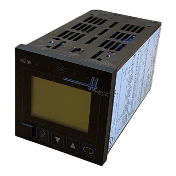
Front view 9499-040-44311 Front view LED 2 e.g. cooling LED 3 e.g. alarm 1 LED 1 e.g. heating LED 4 e.g. alarm 2 Locking screw Display e.g. trend Selector key PC interface Increment key (z) Manual/automatic key Decrement key (u) Locking screw: locks the controller module in the housing. -
Page 6: Electrical Connections
Electrical connections 9499-040-44311 Wire-hook switch S: Its switching status is signalled by function STATUS and can be used in the engineering. After delivery, the switch is open. For closing, release the locking screw, withdraw the controller module from the housing, close the Wire-hook switch. Insert the unit and lock it with the screw. - Page 7 Electrical connections 9499-040-44311 plates for switching units > and door earthing strips <.Control- lers KS40/50/90 y and KS92/94 x are shown as an example for earthing. The max. length of connections is 20 cm (see relevant ope- rating instructions). Generally, the yellow/green protective earth is too long to provide a high-quality ground connection for high-frequency interferences.
- Page 8 Electrical connections 9499-040-44311 galvanic isolations di (-) CAN-GND di 1 (+) CAN-H di 2 (+) CAN-L + Volt OUT5 INP5 + mA _ Volt / mA 100% OUT4 INP6 0/4...20mA OUT2 0/4...20mA Volt INP1 OUT1 0/4...20mA 100% 24 V 24 V di 8 ( ) di 9 ( ) di 3 ( )
- Page 9 Electrical connections 9499-040-44311 Analog inputs (r connecting diagram) Thermocouples (a) No lead resistance adjustment. Internal temperature compensation: compensating lead up to the instrument terminals. With AINP1, STK = int.CJC must be configured. External temperature compensation: Use separate cold junction reference with fixed reference temperature. Compensating lead is used up to the cold junction reference.
- Page 10 Electrical connections 9499-040-44311 Versions with integrated supply voltage The potential-free supply voltage can energize a 2-wire transmitter or max. 4 control inputs. Its output connectors are selectable by means of 3 S.I.L. switches: Connectors Ü Ö Remarks Only available with INP1 configured for current or thermocouple 14 (+) 12 (-) T open closed...
-
Page 11: Menus
Menus 9499-040-44311 Menus Instrument operation is menu-guided. Distinction of complete dialog and short-form dialog is made. In the complete dialog, the main menu with its sub-menus is displayed, i.e. all permitted settings are selectable. During short-form dialog, the main menu is switched off, i.e. unauthorized or accidental access is prevented and only the operating page menu with the permit- ted operating pages is selectable. - Page 12 Menus 9499-040-44311 Prior to operating version 2, KS 98: was displayed additionally in the headers of the main menu and the five sub-menus. Example: KS 98: Main menu Selection (switching on and operating pages) After power switch-on, the instrument starts up with a logo and Main menu wait! and then the main menu is displayed during several seconds.
- Page 13 Menus 9499-040-44311 Adjusting values Values in marked lines of pages can be adjustable. For this, the required line or value is marked with ID (inverse display). When confirming the value with M, it starts blinking and can be adjusted with ID. When reaching the required value, confirm it with M.
-
Page 14: Maintenance
9499-040-52711 For the I interface description 9499-040-57011 NTER Engineering manual manual 9499-040-44911 This manual includes the operating instructions 9499-040-45701 for the engineering tool and the manual 9499-040-50611 for KS 98 Multi Function Unit. Behaviour in case of trouble... -
Page 15: Scaling And Calculation Functions
Scaling and calculation functions 9499-040-44311 Software functions The function blocks are described basically. Analog inputs are described with x, digital inputs with d, analog outputs with y and digital outputs with z. Range “Real” is within -29 999 and 200 000. The max. permissible length of the value is 6 digits (inclusive of minus sign and decimal point), with max. - Page 16 Scaling and calculation functions 9499-040-44311 SQRT (square root function - no. 08) × Parameter Description Values Default Multiplication factor Real Input offset Output offset SCAL (scaling - no. 09) × Parameter Description Values Default Multiplication factor Real Offset Exponent -7...+7 10EXP (10s exponent - no.
-
Page 17: Non-Linear Functions
Non-linear functions 9499-040-44311 Non-linear functions 10.1 (dead band - no. 20) with x1 < L with x1 = L...H with x1 > H y = x - High Parameter Description Values Default y = x - Low Lower limit value High Real High... - Page 18 Trigonometric functions 9499-040-44311 11.4 (cotangent function - no. 83) cot 1) Parameter Description Values Default (y1) = cot (x1) Select Select Unit: degree of angle Unit: arc measure 11.5 ARCSIN (arcus sinus function - no. 84) arcsin 1) Parameter Description Values Default (y1) = arcsin (x1) Select Unit: degree of angle...
-
Page 19: Logic Functions
Logic functions 9499-040-44311 Logic functions 12.1 (AND gate - no. 60) d AND d AND d AND d & 12.2 (inverter - no. 61) 12.3 (OR gate - no. 62) d OR d OR d OR d 12.4 BOUNCE (debouncer - no. 63) for de-bouncing a logic signal Delay Parameter Description... - Page 20 Logic functions 9499-040-44311 12.7 MONO (monoflop - no. 66) Positive pulse of length T1 at z1, if a positive flank is detected at d1 (0 r 1) and Positive pulse of length T2, when a negative flank is detected at Mode1 d2 (1 r 0).
-
Page 21: Signal Converters
Signal converters 9499-040-44311 Signal converters 13.1 AOCTET data type conversion Function AOCTET converts an analog value (X1) into the individual bytes (Ooct1-4) of a data type as used e.g. for transmission via the CAN bus ( see CPREAD / CPWRIT ). In the CAN notation, the bytes are transmitted in Intel format. - Page 22 Signal converters 9499-040-44311 13.5 COUN (up/down counter - no. 74) The events (0 r 1) at d1 are counted up and the events at d2 are counted down. Condition: the non-counting input is not connected, reset & or connected to 1. During carry or borrow, the relevant output is 0. preset Parameter Description Values...
-
Page 23: Time Functions
Time functions 9499-040-44311 Time functions 14.1 LEAD (differentiator - no. 50) × y t t ( \ ) + × x t x t t ( ) \ ( \ ) ] reset calculation cycle time x1(t) instantaneous x1 time constant x1(t-ts) previous x1 Mode gain... - Page 24 Time functions 9499-040-44311 14.4 DELA1 (delay time 1 - no. 53) Delay time with TT = n . ts (d3 not wired) or shift register of depth n (d3: 0 r 1 as clock). reset preset Parameter Description Values Default clock Delay factor 0/1/...255...
- Page 25 Time functions 9499-040-44311 14.7 TIMER (time switch 1 - no. 67) z1 is switched on at absolute time TS (Mo=month, D=day, H=hour, Mi=minute) and switched off again TE later disabl (D=days, H=hours, Mi=minutes). Switching can be done once or cyclically, and suppressed with d1 = 1. TS.Mo TE.D y1 indicates the actual weekday (0...6 = Su...Sa)
-
Page 26: Selection And Storage
Selection and storage 9499-040-44311 Selection and storage 15.1 EXTR (extreme value selection - no. 30) The values of x1...x3 are output sorted according to height at y1...y3. y4...y6 indicate the relevant input number. With equality y1>y2>y3 MaxNo the distribution is at random. If an input is not wired or >0,5 . 10 or <-0,5 . - Page 27 Selection and storage 9499-040-44311 15.6 SELV1 (variable selection - no. 35) y1 = x1 (d1 = 0, d2 = 0) y1 = x3 (d1 = 1, d2 = 0) 0 0 1 y1 = x2 (d1 = 0, d2 = 1) y1 = x4 (d1 = 1, d2 = 1) 0 1 2 1 0 3...
-
Page 28: Limit Signalling And Limiting
Limit signalling and limiting 9499-040-44311 Limit signalling and limiting 16.1 ALLP (alarm and limiting with fixed limits - no. 40) Signal x1 is monitored for 2 low (L1, L2) and 2 high limit values (H1, H2). Additionally min. and max. limiting is applied to the sig- nal (L1, H1). - Page 29 Limit signalling and limiting 9499-040-44311 16.4 VELO (rate-of-change limiting - no. 43) x1 is passed through to y1, however, its rate of change is limited to a positive and / or a negative maximum value (gradient). Parameter Description Values Default GrX+ Positive gradient (1/s) Î...
-
Page 30: Visualization
Visualization 9499-040-44311 Visualization 17.1 VWERT (display / definition of process values - no. 96) For display or alteration of 6 analog or digital values in 6 display lines. With d1 = 1 the operating page is not displayed. With d2 = 1 the values are not adjustable by means of keys ID. - Page 31 Visualization 9499-040-44311 17.2 VBAR (bargraph display - no. 97) For display of 4 analog values, 2 thereof as bargraphs. The bar- graphs can be horizontal or vertical. The values of x1 and x2 can also be altered. With d1 = 1 this operating page is not displayed. With d2 = 1 the values are not adjustable using keys ID.
- Page 32 Visualization 9499-040-44311 17.3 VPARA (parameter operation - no. 98) For common display and adjustment of max. 6 parameters of ot- her function blocks on 6 display lines. When value 0 is specified as block number, the corresponding line is a text line. With in- put (x) connected, keys ID are without effect but display and output follow the input with positive edge at d3 (0r1).
- Page 33 Visualization 9499-040-44311 17.4 VTREND (trend display - no. 99) For collection and display of the last 100 analog values of x1. These values are displayed in a trend curve. Sampling interval (Sample) and time unit (Unit) are adjustable. With d1 = 1 X 100 the operating page is not displayed.
-
Page 34: Communication
Communication 9499-040-44311 Communication ISO 1745 Max. 20 functions L1READ and L1WRIT are configurable (blocks 1...20), whereby any combination is possible. In the functions, any data can be used. 18.1 L1READ (read level1 data - no. 100) Any 7 analog process values (x1...x7) and any 12 digital status Interface informations (d1...d12) of the engineering are composed into a data set for the digital interface. - Page 35 Communication 9499-040-44311 PROFIBUS NTER Max. 4 functions DPREAD and 4 functions DPWRIT are configurable (blocks 1...4 or 11...14), whereby any combination is possible. In the functions, any data can be used. 18.3 DPREAD (read level1 data via PROFIBUS / I - no.
-
Page 36: Ks98+ I/O Extension
The additional CANopen interface extends the multi- function unit functionality already in the basic version by Extension of the number of local I/O by means of the modular PMA RM 200 I/O system open connection of PMA multi-temperature controllers KS800 / KS 816 with CANopen interface... - Page 37 KS98+ I/O extension 9499-040-44311 19.1 RM 211, RM212 and RM213 basic modules An RM 200 system comprises a basic module (housing) for mounting on a snap-on rail with 3, 5 or 10 sockets. The left socket is generally reserved for bus coupler module +24 V +24 V +24V...
- Page 38 KS98+ I/O extension 9499-040-44311 19.3 RM_DI (RM 200 - digital input module - no. 15) Function RM_DI handles the data of connected digital input modules. Configuration Description Values 0: RM 241 = 4 x 24 VDC MTyp Module type 1: RM 242 = 8 x 24 VDC 2: RM 243 = 4 x 230 VAC Direct or inverse output of input signal 1? direct...
- Page 39 KS98+ I/O extension 9499-040-44311 19.5 RM_AI (RM 200 - analog input module - no. 17) Function RM_AI handles the data of connected analog input modules. Configuration Description Values 0: RM 221-0 = 4x 0/4...20 mA 1: RM 221-1 = 4x -10/0...10 V 2: RM 221-2 = 2x 0/4...20 mA + 2x -10/0...10 V 3: RM 222-0 = 4x 0/4...20 mA, TPS 4: RM 222-1 = 4x -10/0...10 V, potentiometer, TPS...
- Page 40 KS98+ I/O extension 9499-040-44311 19.6 Potentiometer connection and adjustment only RM222-1 Connection: Modules RM 222-1 and RM222-2 are also suitable for connection of potentiometers. Max. two potentiometers can be connected to module RM222-2 and max. four potentio- meters can be connected to module RM 222-1. For potentiometer measurement, a voltage divider circuit is used.
- Page 41 KS98+ I/O extension 9499-040-44311 19.7 RM_AO (RM 200 - analog output module - no. 18) Function RM_AO handles the data of connected analog output modules. Configuration Description Values 0: RM 231-0 = 4x 0/4...20 mA / 4x 0...10 V 1: RM 231-1 = 4x 0/4...20 mA / 2x 0...10 V / MTyp Modultype 2x -10...10V...
- Page 42 KS98+ I/O extension 9499-040-44311 19.8 RM_DMS strain gauge module Function RM_DMS reads data from a special strain gauge module of KS98+ I/O exten- sion with CANopen. Max. 2 strain gauges can be connected to the module. The measu- red values are available at outputs AI 1 and AI 2. The two measurements can be influenced via digital command inputs, e.g.
-
Page 43: Cross Communication Ks 98Plus - Ks98Plus
9499-040-44311 Cross communication KS 98plus - KS98plus Whilst data exchange between KS 98+ and RM200, KS800 or KS816 must be carried out exclusively via KS98+ as a master, “cross commu- nication” is possible directly. Data exchange between several KS 98+ of a CAN network is via send blocks (CSEND;... - Page 44 Cross communication KS 98plus - KS98plus 9499-040-44311 20.2 CSEND (send block numbers 21, 23, 25, 27 - no. 57) Function CSEND makes the data for other KS98+ available on the CANo- pen bus. The data can be read using the CRCV function by the other multifunction units.
-
Page 45: Ks 800 And Ks 816 Connection
KS 800 and KS 816 connection 9499-040-44311 KS 800 and KS 816 connection Function blocks C_KS8x and KS8x can be used for communicati- on between multifunction unitKS98+ and multi-temperature con- trollers KS 800 and KS 816. Each KS 800 or KS 816 is allocated a node function C_KS8x. The KS8x functions are allocated to the individual controllers of KS 800 (max. - Page 46 KS 800 and KS 816 connection 9499-040-44311 21.1 C_KS8x KS800 and KS 816 nodefunction - no. 58 Node function C_KS8x represents the interface to one of the multi-temperature controllers KS 800 or KS 816. Analog outputs C1 … C16 can be used for connec- ting the KS8x functions which represent a controller of KS 800 (max.
- Page 47 KS 800 and KS 816 connection 9499-040-44311 21.2 KS8x (KS 800 and KS 816 controller function - no. 59) The KS8x functions each handle a controller from KS 800 or KS 816. The analog or digital inputs can be used for sending the signals for control to the controller in KS800/16.
-
Page 48: Description Of Ks98 Can Bus Extension
Description of KS98 CAN bus extension 9499-040-44311 Description of KS98 CAN bus extension 22.1 CPREAD (CAN-PDO read function) Function CPREAD is used for read access to instrument PDOs. Due to the normal quantity of min. 2 PDOs per instrument, the data quantity of 2 PDOs with 2 COB-IDs was grouped in one block. - Page 49 Description of KS98 CAN bus extension 9499-040-44311 22.2 CPWRIT (CAN-PDO write function) Function CPWRITE is used for write access to instrument PDOs. Because of the normal quantity of min. 2 PDOs per instruments, the data quantity of 2 PDOs with 2 COB-IDs was grouped in a block.
- Page 50 Description of KS98 CAN bus extension 9499-040-44311 22.3 CSDO CAN-SDO function Function CSDO permits access to the CAN bus by means of SDOs (Service Data Ob- jects). SDOs are used for asynchronous data exchange without real-time inquiry. Transmission started by the trigger input is always confirmed by the receiver, pos- sibly during data inquiry along with value transmission.
-
Page 51: Programmer
Programmer 9499-040-44311 Programmer Valid for DPROG and APROG: With p-show = 1 and program in line Status, the direct parameter page can be indicated. It shows all times and set-points belonging to a program. The marked line scrolls up and down and the values can be adjusted. A new ProgNo is effective only after reset. - Page 52 Programmer 9499-040-44311 23.1 APROG (analog programmer - no. 24) / APROGD (APROG data - no. 25) Direct parameter page Operator page ProgNo 111: Programm analog Data are contained in APROGD. SegNo More than 10 segments: weff cascade APROGD several programs (recipes): wseg 10:30 TNetto...
- Page 53 Programmer 9499-040-44311 23.2 DPROG (digital programmer - no. 27) / DPROGD (DPROG data - no. 28) Direct parameter page Operator page Data are contained in DPROGD. More than 10 segments: DPROGD must be 108: Programm digital ProgNo cascaded, several programs (recipes): SegNo select DPROGD via SELV2.
-
Page 54: Controllers
Controllers 9499-040-44311 Controllers The analog inputs and outputs are determined as follows: OVC+ Input; override control + OVC- Input; override control - ParNo Only with CONTR+; input: required parameter set; output: effective parameter set Output; internal set-point Weff Output; effective set-point Wext Input;... - Page 55 Controllers 9499-040-44311 24.1 CONTR (control function - no. 90) Controller with one con- Page for self-tuning operator page trol parameter set. With d1 = 1 the operating page is not displayed. xeff With d2 = 1 the values are adjustable neither with keys ID nor with weff(y) d3 (z) / d4 (u).
- Page 56 Controllers 9499-040-44311 Configuration Description Values Default Configuration Description Values Default Signallers: No tracking of Wint WTrac 1 Output Set-point tracking 2 Outputs Process value tracking 2-point controller Function of ratio controller: 3-point controller (x1 + N0) / x2 Ratio Heating/cooling switching (x1 + N0) / (x1 + x2) Heat.cont./cool.cont.
- Page 57 Controllers 9499-040-44311 24.2 CONTR+ (extended control function - no. 91) Controller with six con- Page for self-tuning operator page trol parameter sets. With d1 = 1 the operat- ParNo ing page is not dis- xeff played. With d2 = 1 the values are alterable nei- ther with keys ID nor weff/y...
- Page 58 Controllers 9499-040-44311 Value Configuration Description Values Default Configuration Description Default Signaller: No tracking of Wint WTrac 1 Output Set-point tracking 2 Outputs Process value tracking 2-point controller Function of ratio controller: 3-point controller: (x1 + N0) / x2 Ratio Heating/cooling switching (x1 + N0) / (x1 + x2) Heat.
- Page 59 Controllers 9499-040-44311 24.3 PIDMA (controller function, No.93) Self optimization page operating page Controller with one set of control param- eters. With d1 = 1 the xeff operating page is not shown. With d2 = 1 the values are neither weff(y) with ID keys nor with d3 (z) / d4 (u) y(xeff/xw)
- Page 60 Controllers 9499-040-44311 Configuration Description Values Default Configuration Description Values Default Controller type-selction: Tracking-Funktion 2-point controller No tracking of Wint WTrack Continuous controller Set-point tracking Standard Process value tracking With position feedback. Yp Function of ratio controller: 3-point controller: (x1 + N0) / x2 Ratio Heating/cooling switching (x1 + N0) / (x1 + x2)
-
Page 61: Inputs
Inputs 9499-040-44311 Inputs 25.1 AINP1 (analog input 1 - no. 110) For direct connection of temp. sensors, for resist. transducers and standard signals For INP1 configuration and parameter setting. Block number 61, calculated once per time slot. Parameter Description Values Default lock x1in Meas.value correction P1, input... - Page 62 Inputs 9499-040-44311 25.2 AINP3...AINP6 (analog inputs 3...6 - no. 112...115) For connection of standard signals, AINP6 also for resistance transducers, AINP3 also for dc voltage -50...1300 mV (9407-9xx-x2xx1) For INP3...INP6 configuration and parameter setting. Block num- bers 63...66, calculated once per time slot. AINP lock Parameter...
-
Page 63: Outputs
Outputs 9499-040-44311 Outputs 26.1 OUT1...OUT5 (process outputs 1...5 - no. 116...120) For OUT1...OUT5 configuration and parameter setting. Block numbers 81...85, calculated once per time slot. OUT1 Relais OUT2 Configuration Description 1/2 3 4/5 Values Def. Mode Sign. source: d1 f f f x100 (digital) Sign. -
Page 64: Zusatzfunktionen
Zusatzfunktionen 9499-040-44311 Zusatzfunktionen 27.1 (LED display - no. 123) For configuration of the four LEDs. ¬ Block number 96, calculated once per time slot. LED 1 Inv1 Parameter Description Values Default ¬ LED2 Inv1... No inversion (LED = d) Inv2 ¬... - Page 65 Zusatzfunktionen 9499-040-44311 27.4 CONST (constant function - no. 126) 16 analog values and the logic levels 0 and 1 are made availa- ble. Block number 99, configured firmly once. Parameter Description Values Default C1... Analog constants Real 27.5 SAFE (safety function - no. 94) For generation of 8 defined analog output values and digital le- vels.
-
Page 66: Ks98 I/O Extension Modules
KS98 I/O extension modules 9499-040-44311 KS98 I/O extension modules For mounting in KS98: 9407 - 9xx - x3xx1 and 9407 - 9xx - x4xx1. Safety hints Connection Maintenance: ESD ! KS98 engineering must be ta- No particular maintenance is required for the units. contains electrostatically sensitive ken into account, because it de- components... - Page 67 KS98 I/O extension modules 9499-040-44311 28.1 Electrical connections of modular option C Resistive input (9407-998-0x201) 4-wire 3-wire 2-wire potentiometer TC, mV, mA / V inputs (9407-998-0x211) / (9407-998-0x221) Voltage / current outputs (9407-998-0x301) / (9407-998-0x311) do 1 / 2 (+) Combined digital inputs/ do 1 di 1 (+)
-
Page 68: Modular I/O Extension Modules
Modular I/O extension modules 9499-040-44311 Modular I/O extension modules 29.1 TC_INP (analog input card TC, mV, mA, No. 46) Analog input, plugs into modular option card C For configuration and parameter setting of analog inputs R_INP. The inputs are invariably calculated once per time slot. Parameter Description Values Default... - Page 69 Modular I/O extension modules 9499-040-44311 29.2 F_INP (frequency/counter input, No. 76) The frequency/counter input plugs into modular options card C . For input F_INP configuration and parameter setting. The input is calculated once per time slot. Configuration Description Values Default DigInput rcontrol input Count_1...
- Page 70 Modular I/O extension modules 9499-040-44311 29.3 R_Inp (analog input card Pt100/1000, Ni 100/1000, resistance, potentiometer, No. 77) Analog input, plugs into modular options card C For analog input R_INP configuration and parameter setting. The inputs are calculated invariably once per time slot. Parameter Description Values Default x1a in Measured value correction Inp_a, P1 input value...
- Page 71 Modular I/O extension modules 9499-040-44311 29.4 U_INP (analog input card -50...1500mV, 0...10V, no. 78) Analog input, plugs into modular options card For analog input U_INP configuration and parameter setting. The input is calculated invariably once per time slot. Parameter Description Values Default x1a in Measured value correction Inp_a, P1 Input value...
- Page 72 Modular I/O extension modules 9499-040-44311 29.5 I_OUT (analog output card 0/4...20mA, +/-20mA, No. 47) Analog output, for inserting into modular options card C For analog output I_OUT configuration and parameter setting. The output is calculated invariably once per time slot. Configuration Description Values Default...
- Page 73 Modular I/O extension modules 9499-040-44311 29.7 DIDO (digital input/output card, No. 44) Digital input/output card, plugs into modular options card C For digital input/output DIDO configuration and parameter setting. The function block is calculated invariably once per time slot. Configuration Description Values Default direct - HW input di1 direct at z1...
-
Page 74: Function Management
Function management 9499-040-44311 Function management Max. 350 function blocks can be used. Each function requires a defined portion of the working memory and a defined calculation time. 30.1 Memory requirement and calculation time Time % Memory % Time % Memory % Time % Memory % Function... - Page 75 Function management 9499-040-44311 30.2 Sampling intervals The sampling intervals for conversion of input signals into internal Input or output Interval values and conversion of internal values into output signals (hardwa- INP1 200 ms re conversion) are given in the table opposite. INP3 / INP4 100 ms INP5...
- Page 76 9499- 040- 44311 Subject to change without notice © PMA Prozeß- und Maschinen-Automation GmbH Printed in Germany 9499-040-44311 (12/2005) Postfach 310 229, D - 34058 Kassel...
Need help?
Do you have a question about the KS 98 and is the answer not in the manual?
Questions and answers