Table of Contents
Advertisement
Available languages
Available languages
Quick Links
HARRIS
Gas Distribution Equipment
THIS BOOKLET CONTAINS PROPRIETARY INFORMATION FROM THE HARRIS PRODUCTS GROUP. IT IS PROVIDED TO THE PURCHASER SOLELY FOR USE IN CONJUNCTION WITH AUTOMATIC
SWITCHOVER MANIFOLDS MODEL 240 SERIES. © 2013 THE HARRIS PRODUCTS GROUP - A LINCOLN ELECTRIC COMPANY.
Important
Installation and operation of compressed gas equipment should only be performed by experienced operators and installers who know the general principles and safety precautions to
be observed in handling compressed gases. If you are not certain you fully understand the safety precautions for handling compressed gases, please contact The Harris Products Group,
or, your local gas supplier.
Do not permit untrained persons to install, operate or maintain this equipment. Do not attempt to install or operate this equipment until you have read and fully understand these
instructions. If you do not fully understand these instructions, contact The Harris Products Group.
Extra copies of this instruction manual are available from The Harris Products Group upon request.
1. General Safety Precautions
Protect yourself and others. Read and understand the following instructions before attempting to use this equipment. Failure to understand and follow these instructions can result
in serious personal injury and/or damage to the equipment. Because of the many potential hazards associated with compressed gases, read the Material Safety Data Sheet for each
gas you will be using.
1. Know and understand the physical and chemical properties of the gas being used.
2. Observe general precautions for the use of gases.
3. Observe safety precautions for the gas being used.
4. Do not use this equipment with gases that are not compatible with the materials of construction. The use of gases not compatible with the materials of construction may cause
damage to the equipment or injury to personnel.
5. Many gases can cause asphyxiation by displacing oxygen in the atmosphere. Make certain the area where these manifolds are operated is well ventilated.
6. Do not release asphyxiant, toxic or flammable gases in the vicinity of personnel. Use this equipment only in well ventilated areas. Vent gases to the outside atmosphere and in an
area away from personnel. Be sure that venting and disposal methods are in accordance with Federal, State, Provincial and local requirements. Locate and construct vent lines to
prevent condensation or gas accumulation. Be sure the vent outlet cannot be obstructed by rain, snow, ice, insects, birds, etc. Do not inter-connect vent lines; if more than one vent
is needed, use separate lines.
7. Relief devices should be installed and properly vented in all gas handling systems to protect against equipment failure and over-pressurization.
8. Never connect this equipment to a supply source having a pressure greater than the maximum rated pressure. Refer to the Product Specifications for maximum inlet pressures.
9. Never permit oil, grease or other combustible materials to come in contact with cylinders, manifolds, and connections. Oil and grease may react and ignite when in contact with some
gases – particularly oxygen and nitrous oxide.
10. Cylinder, header, and master valves should always be opened very s-l-o-w-l-y. Heat of recompression may ignite combustible materials.
11. Flexible hoses should never be kinked, twisted or bent into a radius smaller than 3 inches. Mistreatment may cause the flexible hoses to burst.
12. Do not apply heat. Some materials may react and ignite while in contact with some gases – particularly oxygen and nitrous oxide.
13. Cylinders should always be secured with racks, chains, or straps. Unrestrained cylinders may fall over and damage or break off the cylinder valve which may propel the cylinder with
great force.
14. Do not use leak test solution that contains ammonia. Solutions containing ammonia may cause brass tubing to crack.
15. Always use oxygen compatible leak test solution on oxygen or nitrous oxide service equipment.
2. Introduction
All Harris Products Group Gas Distribution systems are cleaned, tested and prepared for the indicated gas service and are built following National Fire Protection Association (NFPA)
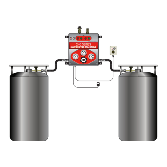
and Compressed Gas Association (CGA) guidelines. The 240 Series Switchover Manifold is intended for gaseous withdrawal from 235 psi (240) or 350 psi (240HP) liquid dewars.
They system consists of a control hub (Box) and hardware to connect two supply banks of gas, one primary and one reserve. The Model 240 Series Switchover Manifold is designed
to provide an uninterrupted supply of gas for the specific application. The control box is designed and built with features providing automatic switchover from the depleted primary
supply bank to the reserve supply bank. Pressure gauges, optional alarm signal connections and lights show system status and alert the need to replace depleted cylinders.
Installation and Operation Manual
LEFT BANK
RIGHT BANK
EMPTY
NORMAL
EMPTY
NORMAL
240 SERIES
240 SERIES
240 SERIES
SWITCHOVER MANIFOLD
SWITCHOVER MANIFOLD
SWITCHOVER MANIFOLD
240 Series
Switchover System
Advertisement
Table of Contents

Related Manuals for Lincoln Electric Harris 240 Series


Summary of Contents for Lincoln Electric Harris 240 Series
- Page 1 THIS BOOKLET CONTAINS PROPRIETARY INFORMATION FROM THE HARRIS PRODUCTS GROUP. IT IS PROVIDED TO THE PURCHASER SOLELY FOR USE IN CONJUNCTION WITH AUTOMATIC SWITCHOVER MANIFOLDS MODEL 240 SERIES. © 2013 THE HARRIS PRODUCTS GROUP - A LINCOLN ELECTRIC COMPANY. Important Installation and operation of compressed gas equipment should only be performed by experienced operators and installers who know the general principles and safety precautions to be observed in handling compressed gases.
-
Page 2: General Instructions
Features of the automatic system include an adjustable line regulator, hoses with built-in check valves, gas economizer circuit , system status lights and wall mounting brackets. 3. Description The Model 240 Series Switchover Manifolds are designed to provide a continuous supply of gas. The system automatically changes from a depleted bank of cylinder(s) in service to a full reserve bank without an interruption of gas supply. - Page 3 Figure 1 1. The control box should be attached to a wall or other secure structure such that the inlet connections to the box are approximately 60 inches from the floor. This dimension can be slightly higher or lower depending on the cylinder height. The mounting dimensions for the control box are shown in Figure 2. 2.
- Page 4 Figure 4 9. Attach the other end of the hose to the cylinder and wrench tighten. Each hose has a gas specific CGA connection with a non-return valve on the end that attaches to the cylinder. Insure that the flow direction arrow on the CGA connection is pointed in the proper direction of gas flow (toward the control box). Otherwise, gas will not flow through the hose when the cylinder valve is opened.
-
Page 5: Replacement Parts
12. Replacement Parts The following chart (Table 2) contains a listing of common replacement parts available for the Model 220 and 240 Series Switchover Manfold Systems. Other replacement parts are available. Contact the Harris Products Group for additional information. Model Control Primary Preset... - Page 6 ESTE MANUAL CONTIENE INFORMACIÓN PROPIETARIA DE HARRIS PRODUCTS GROUP. SE LE PROPORCIONA AL COMPRADOR ÚNICAMENTE PARA QUE LO UTILICE JUNTO CON LOS COLECTORES DE CONMUTACIÓN AUTOMÁTICA DEL MODELO DE LA SERIE 240. © 2013 THE HARRIS PRODUCTS GROUP, UNA EMPRESA LINCOLN ELECTRIC.
-
Page 7: Instrucciones Generales
Entre las características del sistema automático se encuentran: un regulador de línea ajustable, mangueras con válvulas de control integradas, circuito economizador de gas, luces de estado del sistema y soportes de montaje de pared. 3. Descripción Los colectores de conmutación del modelo de la serie 240 están diseñados para proporcionar un constante suministro de gas. El sistema cambia automáticamente de un banco de cilindros agotado en servicio al banco de reserva completo sin que se produzca una interrupción del suministro de gas. - Page 8 Figura 1 1. La caja de control debe estar sujetada a una pared o a otra estructura segura tal que las conexiones de entrada a la caja estén a aproximadamente 60 pulgadas del piso. La dimensión puede ser levemente mayor o menor según la altura del cilindro. Las dimensiones de montaje para la caja de control se muestran en la Figura 2. 2.
-
Page 9: Instrucciones De Operación
Figura 4 9. Sujete el otro extremo de la manguera al cilindro y ajuste con una llave. Cada manguera tiene una conexión conforme a la CGA específica con una válvula de retención en el extremo que se sujeta al cilindro. Asegúrese de que la flecha de dirección del flujo en la conexión CGA apunte a la dirección correcta del flujo de gas (hacia la caja de control). De otro modo, el gas no fluirá... -
Page 10: Piezas De Recambio
12. Piezas de recambio El siguiente cuadro (Tabla 2) contiene una lista de las piezas de recambio comunes disponibles para los sistemas del colector de conmutación del modelo de la serie 220 y 240. Se encuentran disponibles otras piezas de recambio. Comuníquese con Harris Products Group para obtener más información. Número Caja P/N Regulador... -
Page 11: Manuel D'installation Et D'utilisation
SWITCHOVER MANIFOLD CE LIVRET CONTIENT DES DONNÉES EXCLUSIVES À HARRIS PRODUCTS GROUP. IL EST FOURNI À L'ACHETEUR ET UNIQUEMENT DESTINÉ À ÊTRE UTILISÉ AVEC LE COLLECTEUR À COMMUTATEUR AUTOMATIQUE SÉRIE 240. © 2013 THE HARRIS PRODUCTS GROUP - UNE SOCIÉTÉ DE LINCOLN ELECTRIC. Important L'installation et l'utilisation de matériel à gaz comprimé ne doivent être effectués que par des professionnels expérimentés qui connaissent les principes généraux et mesures de sécurité à observer lors de la manipulation de gaz comprimés. - Page 12 Le système automatique se compose des éléments suivants : un détendeur réglable pour conduite, des flexibles avec clapets anti-retour intégrés, un circuit d'économiseur de gaz, des voyants indiquant l'état du système et des supports de fixation muraux. 3. Description Le modèle de collecteur à commutateur série 240 est conçu pour fournir une alimentation continue en gaz. Le système passe automatiquement d'une rangée de bouteilles épuisées en cours d'utilisation à...
- Page 13 Figure 1 1. Le boîtier de contrôle doit être attaché à un mur ou à une autre structure solide de façon à ce que les raccords d'entrée du boîtier soient à environ 60 po (150 cm) du sol. Cette hauteur peut varier légèrement en fonction de la hauteur de la bouteille. Les dimensions pour le montage du boîtier de contrôle apparaissent dans la figure 2. 2.
-
Page 14: Consignes D'utilisation
Figure 4 9. Reliez l'autre extrémité du flexible à la bouteille et serrez à l'aide d'une clef. Chaque flexible comporte un raccord CGA spécifique à chaque gaz avec un clapet de non-retour à l'extrémité à relier à la bouteille. Vérifiez que la flèche indiquant le sens du débit sur le raccord CGA est tournée dans la bonne direction (vers le boîtier de contrôle). Dans le cas contraire, le gaz ne circulera pas dans le flexible, même une fois le robinet de la bouteille ouvert. - Page 15 12. Pièces de rechange Le tableau suivant (tableau 2) présente une liste des pièces de rechange courantes disponibles pour les systèmes de collecteur à commutation série 220 et 240. D'autres pièces de rechange sont disponibles. Communiquez avec The Harris Products Group pour plus de renseignements. Numéro Réf.
- Page 16 9504139 REV.A THE HARRIS PRODUCTS GROUP 062013 1-800-241-0804 www.harrisproductsgroup.com...
Need help?
Do you have a question about the Harris 240 Series and is the answer not in the manual?
Questions and answers