Table of Contents
Advertisement
Quick Links
Advertisement
Table of Contents

Related Manuals for Comino GRANDO RM V2L


Summary of Contents for Comino GRANDO RM V2L
- Page 1 GRANDO RM V2L/V2S USER MANUAL COMINO HOLDING LTD. 2020 GRANDO RM. User Manual...
-
Page 2: Table Of Contents
OVERVIEW 1. INTRODUCTION 1.1 Intended use 2. PRODUCT DESCRIPTION 2.1 Product elements 3. SAFETY INSTRUCTIONS 3.1 Warnings and safety information 3.2 General 3.3 Intended use 3.4 Information for vulnerable people 3.5 Installation 3.6 Usage 3.7 Maintenance and reparations 3.8 Explanations of the signs on the computer 4. - Page 3 OVERVIEW 5.4.2 Control buttons illumination 5.3.4 Actual values menu 5.5 Commands menu 5.6 Control hotkeys 5.7 Service menu 6. POSSIBLE ACCIDENTS 6.1 Possible accidents during operation and self-diagnostic 6.2 Temperature sensors accidents 6.3 Fans and pumps 6.4 Operational reasons 6.5 Failure: No signal from the computing unit 7.
- Page 4 Congratulations on purchasing your GRANDO RM Professional Computing Device. We are pleased to welcome you as a customer. These user instructions contain all safety information and instructions necessary for using your GRANDO RM. Before using your device, please familiarise yourself with all relevant information.
-
Page 5: Introduction
INTRODUCTION Intended Use This device is intended for use as a Professional Computer. The device shall not be used in caustic or potentially explosive environments, or for medical purposes. The device may only be used as specified in these user instruc- tions. -
Page 6: Product Description
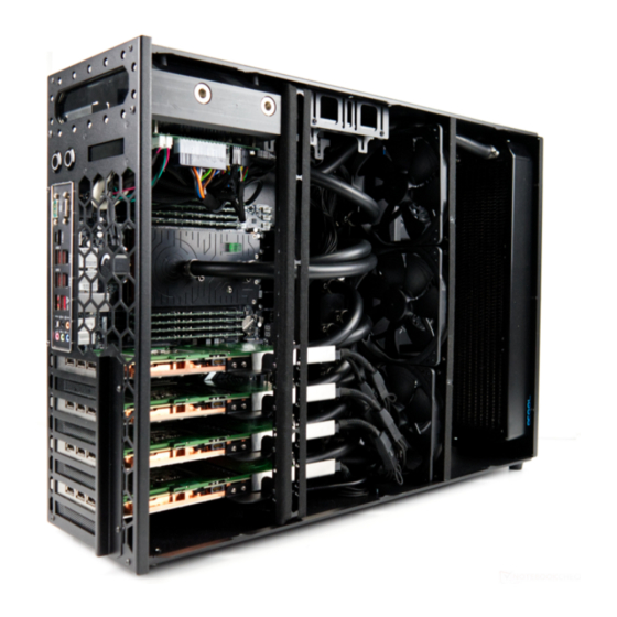
PRODUCT DESCRIPTION Product Elements Display Power button 1 (PB1) Power button 2 (PB2) Rack mounting handles kit GRANDO RM. User Manual... -
Page 7: Safety Instructions
SAFETY INSTRUCTIONS Warnings and safety information WARNING MAKE SURE YOU READ AND UNDERSTAND ALL SAFETY INSTRUCTIONS General • Follow all the instructions. This will avert fire, explosions, electric shock and other hazards that can cause material damage and/or severe injury or death •... -
Page 8: Intended Use
SAFETY INSTRUCTIONS Intended use DANGER THE DEVICE IS NOT SUITABLE FOR USE IN POTENTIALLY EXPLOSIVE ENVIRONMENTS • The device is intended for indoor use. Never use it outdoors • Only use the device within the power limits specified. In the event the device suffers damage, it shall be disconnected from the mains and no longer used •... -
Page 9: Information For Vulnerable People
SAFETY INSTRUCTIONS Information for vulnerable people DANGER NEVER LEAVE CHILDREN UNSUPERVISED WITH THE PACKAG- ING MATERIAL. THE PACKAGING MATERIAL REPRESENTS A RISK OF SUFFOCATION. CHILDREN FREQUENTLY UNDERESTIMATE THESE DANGERS. KEEP CHILDREN AWAY FROM THE PACKAGING MATERIAL. • This device shall not be used by those (including children) with physical or mental-health issues or a lack of experience and/or knowledge, unless they are supervised by somebody who assumes responsibility for their safety and gives them corresponding instructions on how to use... - Page 10 SAFETY INSTRUCTIONS • Only use the mains power cord supplied with the device. Other power cables can damage the device. Do not use the power cable together with any other devices. • Before using the device, check it for any signs of damage. If there is any visible damage, a strong odour or excessive heating of components, disconnect all power plugs immediately and do not use the device.
-
Page 11: Usage
SAFETY INSTRUCTIONS • The device shall be connected to a properly installed and earthed AC power socket. • The mains power socket you use shall be installed close to the device and be easily accessible. • Be particularly careful not to damage the electric plug. Only use the device with an appropriate, correctly installed and easily accessible mains power socket. -
Page 12: Maintenance And Reparations
SAFETY INSTRUCTIONS Maintenance and reparations CAUTION RISK OF EXPLOSION! DO NOT CHANGE THE BATTERY! USED BATTERIES SHALL BE DISPOSED OF IN LINE WITH THE USER INSTRUCTIONS. DO NOT REMOVE THE BATTERY YOURSELF. SEE SECTION DISPOSAL. • Alterations to the device and technical modifications are not permitted. Explanations of the signs on the computer Use the device with care, avoid impacts and mechanical damage, moisture on the device both outside and inside. -
Page 13: Installation
INSTALLATION Unpacking and checking the contents WARNING BEFORE USING THE DEVICE, CHECK IT FOR ANY SIGNS OF DAMAGE. IF THERE IS VISIBLE DAMAGE, DO NOT USE THE DEVICE AND CONTACT THE MANUFACTURER. Unpack the device. Check if the package contains all of the components ordered: •... -
Page 14: Installing
Installing Place the device in a 4U rack space or on a horizontal surface. It’s allowed to place GRANDO RM vertically or horizontally. When installing in a 4U rack space, the rack mount ears kit should be at- tached to the device. GRANDO RM should be installed on the special 19” guide rails or shelf (should be purchased on a separate basis). -
Page 15: Power Supply Unit
GRANDO RM. All PSUs should be powered for correct Device operation. Power supply unit Your system includes Comino Energia power supply unit (PSU) containing up to 3 SFX Power Supply Units (PSUs), 750W each or up to 2 ATX PSU 1700W each depending on configuration. - Page 16 SETTING UP EU Standard US Standard LINE TO NEUTRAL LINE TO NEUTRAL Grounding Grounding CORRECT CORRECT Neutral Neutral A-N 220VAC A-N 120V 1-Ph 220V 120V B-N 220VAC B-N 120V 1-Ph 220V 120V C-N 220VAC C-N 120V 1-Ph 220V 120V DANGER ELECTRICITY WORKS MUST BE COORDINATED WITH A CERTIFIED ELECTRICIAN.
-
Page 17: Inrush Current
SETTING UP Inrush current The power supply must meet inrush requirements for any rated AC volt- age, during turn on at any phase of AC voltage, during a single cycle AC dropout condition, during repetitive ON/OFF cycling of AC, and over the specified temperature rang. -
Page 18: Starting Up The Device
STARTING UP THE DEVICE After connecting the power supplies to the AC mains, the controller will automatically turn on, followed by liquid cooling system self-diagnosis. GRANDO RM is equipped with a two-line show, it will display information about the operating modes of the device. The preliminary stage, performed only when the Internal cooling system is powered for the first time or after power loss recovery. - Page 19 STARTING UP THE DEVICE VER: XXXXXXXXXXX COOL ING SYSTEM SELF-TEST Upon successful completion of the self-diagnostic procedure, the display successively shows: COOL ING SYSTEM SELF-TEST PASSED Further on, the unit goes into standby mode. COOL ING SYSTEM STANDBY GRANDO RM. User Manual...
-
Page 20: Self-Diagnostic Errors
STARTING UP THE DEVICE Self-diagnostic errors In case of error detection or occurrence, the display cyclically shows infor- mation about the error itself and the following message and proceed to error display: When non-critical errors occur that allow further use of the equipment COOL ING SYSTEM SELF-TEST ALARM... -
Page 21: Menu Navigation
STARTING UP THE DEVICE Menu navigation The ACTUAL VALUES menu is displayed by default. For the sake of con- venience, the displayed information can be scrolled using the illuminated buttons of the cooling module via short-time (less than 2 seconds) button press. - Page 22 STARTING UP THE DEVICE GRANDO RM. User Manual...
-
Page 23: Main Part
STARTING UP THE DEVICE Main part The execution of the main part begins when a power-on confirmation sig- nal from Motherboard is received by the Controller. This signal informs the Internal Cooling System about the Motherboard start and the launch of the entire system. -
Page 24: Control Buttons Illumination
STARTING UP THE DEVICE PREV NEXT less than 2 sec CANCEL more than 2 sec 5.4.2 Control buttons illumination • In the process of self-diagnostics: the backlight of both buttons flashes simultaneously with a delay of 1 second on / 1 second off. •... -
Page 25: Actual Values Menu
STARTING UP THE DEVICE To return to the “Actual values” menu press PB1 long-held. Information available for showing on the display: 5.4.3 Actual values menu • T °C of air inlet and outlet of the system (2 sensors): A IR IN:+22.7 C OUT:+23.9 C •... - Page 26 STARTING UP THE DEVICE • T °C of cooling liquid with disconnected sensors or out of range values: WATER IN: N / A OUT: N / A • T (C °), sensors T0 and T5 located on the controller board: T0:+12.3 C T5:+12.3 C •...
- Page 27 STARTING UP THE DEVICE • RPM of backside fans 4-6: FAN’ s RPM F4:N/A F5:N/A F6:N/A • Fans signal loss or in case of out of range values: FAN’ s RPM F1:N/A F2:N/A F3:N/A FAN’ s RPM F4:N/A F5:N/A F6:N/A •...
- Page 28 STARTING UP THE DEVICE • Pump signal loss or in case of out of range values for pumps: PUMP’ s RPM P1:N/A P2:N/A • Displaying the time of the current session: CURRENT UP TIME 999D-24H-60M • Total run time TOTAL RUN TIME 9999D-24H-60M GRANDO RM.
-
Page 29: Commands Menu
STARTING UP THE DEVICE Commands menu: • Command screen for starting the Computing module. Available only in STANDBY mode. COMMAND: TURN ON SYSTEM • Command screen to shutdown the Computing module. Available only in OPERATION mode. COMMAND: SHUT DOWN SYSTEM •... -
Page 30: Control Hotkeys
STARTING UP THE DEVICE • Command screen to reboot the Controller. Available only in STANDBY mode. COMMAND: RESET COOLER Control hotkeys • Holding PB1 and then pressing the PB2 button displays the screen: RESET SYSTEM <<NO YES>> • Then we release both buttons, when PB1 is pressed, the menu screen that preceded the operation returns, when PB2 is pressed, the MB_RE- SET command is sent to the motherboard GRANDO RM. - Page 31 STARTING UP THE DEVICE • If the System is in a STANDBY mode, holding down PB2 and then press- ing PB1 button displays the screen: TURN ON SYSTEM <<NO YES>> We release the PB2 button, when PB1 is pressed, the menu screen that preceded the operation returns, when PB2 is pressed, the MB_POWER command is sent to the motherboard •...
-
Page 32: Service Menu
STARTING UP THE DEVICE Service menu MENU: SERVICE • You can switch between the menu items by short pressing (for less than 2 sec) PB1 {PREV} and PB2 {NEXT} buttons. To enter the section you’ve chosen press and hold PB2 for more than 2 sec. {OK} SERVICE: TEMP PROFILE •... - Page 33 STARTING UP THE DEVICE • You can switch between the profile screens by short pressing (for less than 2 sec) PB1 {PREV} and PB2 {NEXT}. To apply the selected profile, press and hold PB2 for more than 2 sec. {OK} GRANDO RM.
-
Page 34: Possible Accidents
POSSIBLE ACCIDENTS Possible accidents during operation and self-diagnostic: If an Error occurs, the System continues to work, information with a description and an alarm code is displayed, and a warning sound signal is turned on. In case of a Failure, the operation of the Computing Unit is stopped by the Internal Cooling System command with or without delay, depending on the emergency nature. - Page 35 POSSIBLE ACCIDENTS • Failure:Т2 sensor fault (Liquid outlet) WATER SENSOR T2 FAIL F313 • Error: Т3 sensor fault (Air inlet) SENSOR T3 FAIL E314 • Error: Т4 sensor fault (Air outlet) SENSOR T4 FAIL E315 GRANDO RM. User Manual...
-
Page 36: Fans And Pumps
POSSIBLE ACCIDENTS • Failure: Т5 sensor fault (Built-in I2C) SENSOR T5 FAIL F316 Fans and pumps • Error: 1-2 fans fault (1)(2)(3)FAN(S) FAILED E321 • Failure: all 3 fans fault ALL FANS FAILED F322 GRANDO RM. User Manual... -
Page 37: Operational Reasons
POSSIBLE ACCIDENTS • Failure: any pump fault P(1)(2) PUMP FAILED F323 • Failure: both pumps fault ALL PUMPS FAILED F324 Operational reasons • Failure: Т3 excess allowed maximum (Air inlet) AMBIENT TEMP xx C - HIGH F331 MAX AMBIENT TEMP 38 C F331 GRANDO RM. - Page 38 POSSIBLE ACCIDENTS • Failure: Т3 below allowed minimum (Air inlet) AMBIENT TEMP x x C - L O W F332 MIN AMBIENT TEMP 3 C F332 • Failure: Т2 excess allowed maximum (Liquid outlet) WATER TEMP x x C - H IG H F333 MAX WATER TEMP 60 C F333 GRANDO RM.
-
Page 39: Failure: No Signal From The Computing Unit
POSSIBLE ACCIDENTS Failure: No signal from the computing unit MOBO SYNC LO ST F334 CHECK SYNC CAB LE C O N N E C T IO N S YS TE M M A N U A L RES TAR T R E Q I R E D •... - Page 40 POSSIBLE ACCIDENTS • Failure: lack or dump of the + 12V power source +12V POWER SOURCE LOST F336 • Shutdown procedure • Normal (the computing unit is switched off by user) SY S T E M S HUTT IN G D O W N •...
- Page 41 POSSIBLE ACCIDENTS Emergency if the computing module has not not completed its work normally after the controller command SHUTDOWN FA ILURE FORCING SHUTDOWN FORCING SHUTDOWN • With further computing unit reboot It is performed only when the computing unit is switched off due to ac- cidents with unacceptable coolant or ambient air temperatures.
-
Page 42: Shutdown Procedure
SHUTDOWN PROCEDURE Sound alerts In case of error: intermittent sound signal. It is possible to disable the sound by simultaneously holding both of the buttons for 2 seconds. In case of an accident: continuous sound signal. It is disabled only when the Computing unit is completely turned off. - Page 43 TROUBLESHOOTING PROBLEM POSSIBLE CAUSE SUGGESTABLE CORRECTION F311 STM sensor Reset controller in STANDBY mode via is fault or out Commands menu or shut down Device and of range de-energize all PSUs. If this problem repeats, please contact the Manufacturer. E312 T1 liquid inlet Reset controller in STANDBY mode via sensor is fault...
- Page 44 TROUBLESHOOTING PROBLEM POSSIBLE CAUSE SUGGESTABLE CORRECTION E314 T3 air inlet sensor Reset controller in STANDBY mode via is fault or out Commands menu or shut down Device and of range de-energize all PSUs. If this problem repeats, check if the NTC3 sensor is connected to the Controller correctly.
- Page 45 TROUBLESHOOTING PROBLEM POSSIBLE CAUSE SUGGESTABLE CORRECTION E321 Up to 2 fans fault Reset controller in STANDBY mode via Com- (Some of fans fault, mands menu or shut down Device and de-en- at least one is alive) ergize all PSUs. If this problem repeats, check if the faulty fan is connected to the Controller properly.
- Page 46 TROUBLESHOOTING PROBLEM POSSIBLE CAUSE SUGGESTABLE CORRECTION Reset controller in STANDBY mode via F323 Any/All pumps F324 Commands menu or shut down the Device fault and de-energize all PSUs. If this problem repeats, check if the faulty pump is connect- ed to the Controller properly. It is allowed to swap pumps connectors between Controller headers PUMP #1-2 to ensure there is no problem with Controller pump output.
- Page 47 TROUBLESHOOTING PROBLEM POSSIBLE CAUSE SUGGESTABLE CORRECTION If cooling liquid is overheating, please make F333 Liquid overheated sure all fans are operating normally, inlet liquid (T1) is at least 5°C hotter than outlet liquid (T2), outlet air temperature (T4) is at least 5°C higher than inlet air (T3).
- Page 48 TROUBLESHOOTING PROBLEM POSSIBLE CAUSE SUGGESTABLE CORRECTION Please check the PSU#2, which is connect- F336 +12V power source ed to the Controller via 24pin cable. If cable lost or out of range is connected securely, try to swap this PSU with PSU#1 (it powers Motherboard). Loud Pumps operation is not allowed without Pumps operate...
-
Page 49: Maintenance And Cleaning
MAINTENANCE AND CLEANING Checking and refilling coolant Once in 3 (three) months the coolant level in the reservoir should be checked. 9.1.1 V2 Coolant control procedure: 1. Turn the device off. 2. Place the device in a horizontal working position. 3. -
Page 50: Refilling Coolant
MAINTENANCE AND CLEANING 9.1.2 Refilling coolant WARNING WHILE POURING THE COOLANT BE SURE NOT TO SPILL IT OUTSIDE OF THE RESERVOIR. IF THE COOLANT IS SPILLED ON THE HARDWARE IT MIGHT LEAD TO HARDWARE MALFUNCTION. TO SECURE THE HARDWARE PUT PAPER TOWELS AROUND THE RESERVOIR WHILE ADDING THE COOLANT. -
Page 51: Draining The Coolant From The System
MAINTENANCE AND CLEANING 5. Using funnel add the coolant to the system. 6. Screw on 2x coolant filling G1/4” plugs to the reservoir. 7. Install the top panel back. 9.1.3 Draining the coolant from the system: 1. Take off the bottom panel (check the paragraphs 1-4 of installing the 2.5”... -
Page 52: 5" Drives Installation
2.5” DRIVES INSTALLATION 10.1 In the recess on the device back panel, unscrew 4 M3x4 ISO7380 screws fixing the panel with the PSU screwed to it (only for RM V2S) Gently fold back the PSU panel, it will be held on the power cables (only for RM V2S) Unscrew 3 M3x4 ISO7380 screws securing the 2.5”... - Page 53 2.5” DRIVES INSTALLATION Unscrew 2 М3х4 DIN 7991 screws securing the bottom panel (RM V2L only) Slide the 2.5” drive bay panel back so it can be removed completely The drives are located on 2 brackets, each of the brackets is attached to the chassis by 4 M3x4 ISO7380 screws, unscrew them to get the full ac- cess to the drives GRANDO RM.
-
Page 54: Disposal
DISPOSAL 11.1 The new product package, the product parts broken during the operation process, as well as an old product should not be disposed of as ordinary household waste, they contain raw materials and materials that can be re- used. Discarded and unused product parts must be taken to a designated collec- tion center licensed by local authorities. -
Page 55: Warranty
WARRANTY 12.1 Always contact the Manufacturer before returning the device. The warranty period is 12 months from the date of purchase. The defective device shall be sent within two weeks. The warranty is void in the following cases: • Application of external force •... - Page 56 Manufactured by COMINO HOLDING LTD. 1 Fore Street, London, England, EC2Y 9DT GRANDO RM. User Manual...
Need help?
Do you have a question about the GRANDO RM V2L and is the answer not in the manual?
Questions and answers