
Related Manuals for Comino OTTO Prebuilt Series


Summary of Contents for Comino OTTO Prebuilt Series
- Page 1 OTTO Prebuilt Series USER GUIDE COMINO HOLDING LTD. 2020 OTTO PREBUILT SERIES. USER GUIDE...
- Page 2 Requests for authorisa- tions shall be directed in writing to the publisher at the address given below. COMINO HOLDING LTD. 1 Fore Street, info@comino.com London, England, www.comino.com EC2Y 9DT +44 2036709833 OTTO PREBUILT SERIES. USER GUIDE...
-
Page 3: Table Of Contents
Connecting the hoses and cables — B550-I (Part1) 9.17 Riser LED indication 9.18 Installing the bottom panel of the chassis + SSD 9.19 Installing the top and bottom panels 9.20 Installing the side panels 9.21 OTTO PREBUILT SERIES. USER GUIDE... -
Page 4: Introduction
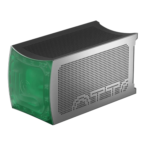
Congratulations on purchasing your COMINO OTTO Professional Computer. We are pleased to welcome you as our customer. This manual contains all safety information and instructions required for using your COMINO OTTO Professional Computer. Before using your device, please familiarize yourself with all relevant in- formation. - Page 5 INTRODUCTION Product elements Ventilation holes Filters Reservoir Magnetic side panels Power cable Ventilation socket holes I/O ports On/Off button USB-A 3.2 Gen 1 Detachable legs (x4) USB-C 3.2 Gen 2 Ventilation holes OTTO PREBUILT SERIES. USER GUIDE...
-
Page 6: Unpacking And Checking The Contents
THE CONTENTS Put the box the right way, cut the adhesive tape on the box with an office knife Check if the package contains all of the components ordered Take Otto out of the box OTTO PREBUILT SERIES. USER GUIDE... - Page 7 After the wet cleaning, wipe your device with a dry soft cloth. It is not allowed to use the following for cleaning: alcohol, alcohol- containing liquids, wipes soaked in alcohol-containing liquids, solvents. Usage of alcohol/solvent for cleaning may cause plastic parts cracking and cloudiness. OTTO PREBUILT SERIES. USER GUIDE...
-
Page 8: Setting Up
WARNING WE SHIP YOUR OTTO WITH THE PROTECTIVE INSERTS PLACED BETWEEN THE COMPONENTS TO PREVENT THEIR DAMAGE, HENCE EXTRACT ALL THE INSERTS BEFORE STARTING THE DEVICE UP TO AVOID THE DANGER OF SYSTEM OVERHEATING! OTTO PREBUILT SERIES. USER GUIDE... -
Page 9: Starting Up The Device
MAINS. SHUTTING DOWN THE DEVICE Press the On/Off button on the device case or switch it off via OS interface function. On/Off button OTTO PREBUILT SERIES. USER GUIDE... -
Page 10: Adjusting The System
CPU/GPU temperatures use ASUS Aura RGB Lighting Control for Graphic card & XG-STATION for sepa- rate adjustment of GPU RGB. ASUS AI Suite and ASUS Aura RGB can be downloaded from ASUS’s official website: https://www.asus.com OTTO PREBUILT SERIES. USER GUIDE... -
Page 11: How To Fill The Coolant
Carefully pour the coolant into the filling port until it reaches the level again. No coolant must be spilt inside the device! 12. Close the G1/4” plug with a hex wrench and place OTTO in its normal position. OTTO PREBUILT SERIES. USER GUIDE... - Page 12 OTTO is raised 40-45º of OTTO side panel and filter to release air.* removed; * — Be careful when working with an open device, for safety reasons we recommend closing the side panel every iteration. OTTO PREBUILT SERIES. USER GUIDE...
-
Page 13: Otto Transformation For Different Cooling Systems
Is designed for building liquid- cooled and hybrid systems. It’s possible to install a GPU with air cooling. This is the transformation we use at Comino for assembling our systems. It works best for liquid cooling. • +18mm Transformation Is designed for liquid-, air- and hybrid systems. - Page 14 • Remove the top panel — 2 • Unscrew 6x bottom screws — 3 • Remove the bottom panel — 4 • Unscrew 4x screws securing the back panel — 5 • Remove the back panel — 6 (x4) (x6) (x6) OTTO PREBUILT SERIES. USER GUIDE...
- Page 15 Push the panels a little (6mm), having previously loosened the screws, since there are folds on the upper and lower parts of the chassis that will not allow removing the back frame. 6мм 6мм 6мм 6мм OTTO PREBUILT SERIES. USER GUIDE...
- Page 16 • Remove the back panel — 3 • Unscrew 2x screws securing the partition to the front frame — 4 • Unscrew 2x screws securing the partition to the power supply bracket — 5 (x2) (x2) (x2) OTTO PREBUILT SERIES. USER GUIDE...
- Page 17 ’+18mm’ level, then take a small SSD/HDD basket (+18mm) and a back panel +18mm • if you need to assemble a ‘+54mm’ level, then take a large SSD/HDD basket (+54mm) and a back panel +54mm OTTO PREBUILT SERIES. USER GUIDE...
- Page 18 — 2 • Remove the connector with the wire — 3 • Install in reverse order to the other back panel Assemble the chassis and screw on the top, bottom and back OTTO covers. OTTO PREBUILT SERIES. USER GUIDE...
-
Page 19: Psu Pinout
PSU PINOUT If your Otto is supplied with Comino Energia SFX PSU, model: CE750A01, please follow the PSU pinout below to use custom cabling set to connect the internal hardware components. PHERIPHERIAL / SSD / PUMP CPU / GPU POWE... -
Page 20: Otto Builder's Edition / Diy / Case Sff. Assembly Schematics
Please refer to the assembly schematics to build your own OTTO on the base of Builder’s Edition or DIY/Case configurations. Assembling the radiator Steps: Install the fans so that the cables are on the nearest fitting on the right. Pass the fan cables under the fastening screws. OTTO PREBUILT SERIES. USER GUIDE... - Page 21 The connection wire must be located on the opposite side of the fan cables. The end of the LED strip must be at least 5.5mm from the hole. Item 2 Item 1 2070 Super Turbo Evo Item 1 2080Ti STRIX OTTO PREBUILT SERIES. USER GUIDE...
-
Page 22: Assembling The Central Panel & Pcie Riser
Thread the Velcro through the holes in the Central Panel (item 2). Connect the Riser to the Holder, then attach them to the Partition with 4xM3 screws (item 2). See view “A”. View “A” Item 3 View “A” Item 2 Item 1 Item 4 OTTO PREBUILT SERIES. USER GUIDE... -
Page 23: Installing The Waterblock Onto Gpu - Nvidia Geforce Rtx 3080/3090 Ref
Installing the waterblock onto GPU — nVIDIA GeForce RTX 3080/3090 REF Screw the waterblock to the GPU according to the scheme below Screw DIN 912 x8 1-4 Pad: 0.5mm 5-6 Pad: 1mm Screw WUERTH 42283 x3 OTTO PREBUILT SERIES. USER GUIDE... -
Page 24: Installing The Waterblock Onto Gpu - Geforce Rtx 3080/3090 Gigabyte
Installing the waterblock onto GPU — GeForce RTX 3080/3090 Gigabyte Screw the waterblock to the GPU according to the scheme below 1-6 Pad: 0.5mm 7-9 Pad: 1mm Screw DIN 912 x9 Screw ISO 7380 x3 OTTO PREBUILT SERIES. USER GUIDE... -
Page 25: Installing The Waterblock Onto Gpu - 2070 Super Turbo Evo
SELF, AND FEEL FREE TO USE OUR EXAMPLE AS A REFERENCE. Installing the waterblock onto GPU — 2070 Super Turbo Evo Screw the waterblock to the GPU according to the scheme below 1. Pad 89x9x0.5mm 2. Pad 5x5x0.5mm OTTO PREBUILT SERIES. USER GUIDE... -
Page 26: Installing The Waterblock Onto Gpu - 2080Ti Strix
FREE TO USE OUR EXAMPLE AS A REFERENCE. Installing the waterblock onto GPU — 2080Ti Strix Screw the waterblock to the GPU according to the scheme below 1. Pad 105x7x0.5mm 2. Pad 107x13x1mm 3. Pad 66x14x1mm 4. Pad 60x7x0.5mm OTTO PREBUILT SERIES. USER GUIDE... -
Page 27: Installing The Gpu Modules - 2070 Super Turbo Evo / 2080Ti Strix
(either under the graphic card, or up around the graphic card). Pull the free ends of the cables into the holes of the chassis, as shown in Item the drawing and leave them free. 2070 Super Turbo Evo 2080 Strix Item 1 Item 2 OTTO PREBUILT SERIES. USER GUIDE... -
Page 28: How To Crimp A Clamp Around A Wire
OTTO BUILDER’S EDITION / DIY / CASE SFF. ASSEMBLY SCHEMATICS How to crimp a clamp around a wire If you choose to use Comino ear clamps please use Boot Clamp Pliers (item 1). Item 1 Steps: Put the clamp on the hose. -
Page 29: Installing The Reservoir
Crimp the hose (item 2) on the GPU water block. If necessary, cut the length of the hose locally. Leave the loose hose ends free. Item 1 Item 2 Item 1 Item 1 Item 1 OTTO PREBUILT SERIES. USER GUIDE... -
Page 30: Installing The Radiator - 2070 Super Turbo Evo
(if necessary, in place, cut the hose). Then place the Radiator module on the chassis and screw down with the screws. Pull the cables from the fans and LED strip through the hole in the corner of the chassis. OTTO PREBUILT SERIES. USER GUIDE... -
Page 31: Installing The Radiator - 2080Ti Strix
2070 Super Turbo Evo installation process. Note, that the GPU hose length for 2070 Super Turbo Evo and for 2080Ti Strix differs. OTTO PREBUILT SERIES. USER GUIDE... -
Page 32: Installing The Button, The Usb And The Rgb Led
Install the power button (item 9) in the chassis. Pass to the next assembly step along with the bottom cover and its fasteners. Item 7 Item 9 Item 1 Item 6 Item 4 Item 3 Item 2 Item 5 Item 8 OTTO PREBUILT SERIES. USER GUIDE... -
Page 33: Installing The Motherboard B550-I / Z490-I
Install the motherboard with water block and accessories (item 1) on the chassis by attaching the screws (item 2). Insert the riser (item 3) into the motherboard. Do not connect cables and hoses. Item 1 Item 3 Item 2 OTTO PREBUILT SERIES. USER GUIDE... -
Page 34: Assembling The Psu Module
Remove the protective film on one side and stick the Velcro for Cable management (item 1) on the PSU as shown in the image. Then remove the protective foil from the other side and glue the Ca- ble management (item 2). Item 1 ON/OFF Switch Item 2 OTTO PREBUILT SERIES. USER GUIDE... -
Page 35: Installing The Psu Module
Install the bushing (item 3) on the wire, then place the wire with the bushing and the hose in the grooves of the chassis, then fix it with the panel (item 4). Item 2 Item 1 Item 3 Item 4 OTTO PREBUILT SERIES. USER GUIDE... -
Page 36: Connecting The Hoses And Cables - Z490-I (Part1)
Route a hose from the reservoir and connect it to the motherboard waterblock inlet fitting as shown in the diagram. Trim the length in place. The hoses should not rest on the RAM and riser! OTTO PREBUILT SERIES. USER GUIDE... - Page 37 Connect the power cable from the graphic card to the power supply. Fasten the excess wire length with Velcro in the cable channel. Connect the power cables (24pin and 8pin) to the motherboard. Pheripherial/ SSD/ Pump/ Riser CPU/ GPU Power To Motherboard Sense 4Pin OTTO PREBUILT SERIES. USER GUIDE...
-
Page 38: Connecting The Hoses And Cables - B550-I (Part1)
Сut the unused hose lenght. The hoses should not rest on the RAM and riser! (If necessary, the hose from the reservoir to the inlet fitting can be routed along an alternative path (shown by a dotted line)) OTTO PREBUILT SERIES. USER GUIDE... - Page 39 Connect the power cable from the graphic card to the power supply. Fasten the excess wire length with Velcro in the cable channel. Connect the power cables (24pin and 8pin) to the motherboard. Pheripherial/ SSD/ Pump/ Riser CPU/ GPU Power To Motherboard Sense 4Pin OTTO PREBUILT SERIES. USER GUIDE...
-
Page 40: Riser Led Indication
LED indication on both riser and edge-riser: Riser Green — power on (1) Green — X8 mode OK (2) Green — X16 mode OК (3) Edge-Riser Green — X8 mode OK (1) Green — X16 mode OK (2) OTTO PREBUILT SERIES. USER GUIDE... -
Page 41: Installing The Bottom Panel Of The Chassis + Ssd
(item 2). Connect the SSD to the motherboard and the power supply. Install the panel with the SSD on the chassis and fasten it with screws (item 3). Item 3 Item 2 Item 1 OTTO PREBUILT SERIES. USER GUIDE... -
Page 42: Installing The Top And Bottom Panels
Push the filters into the grooves of the top and bottom panels. Fasten the filter panels to the chassis with 12 screws (item 1). Install the Legs (item 2) into the outermost holes of the bottom panel. Item 2 Item 1 OTTO PREBUILT SERIES. USER GUIDE... -
Page 43: Installing The Side Panels
Attach the filters (item 1) to the chassis and check that all 4 latches are engaged. Install the filters with their Front panels towards the reservoir. Install side panels (item 2). Item 2 Item 1 Item 1 Item 2 OTTO PREBUILT SERIES. USER GUIDE... - Page 44 FOR NOTES OTTO PREBUILT SERIES. USER GUIDE...
- Page 45 COMINO HOLDING LTD. 1 Fore Street, London, England, EC2Y 9DT info@comino.com www.comino.com +44 2036709833 OTTO PREBUILT SERIES. USER GUIDE...
Need help?
Do you have a question about the OTTO Prebuilt Series and is the answer not in the manual?
Questions and answers