Yaesu FT-767GX Operating Manual
Hide thumbs
Also See for FT-767GX:
- Service manual (153 pages) ,
- Technical supplement (152 pages) ,
- Operating manual (40 pages)
Table of Contents
Advertisement
Quick Links
Advertisement
Table of Contents

Related Manuals for Yaesu FT-767GX


Summary of Contents for Yaesu FT-767GX
- Page 1 FT-767GX OPERAT/NG MANUAL Y AESU MUSEN CO., l TO. 1 J�. TI) 4.PO>l...
-
Page 2: Table Of Contents
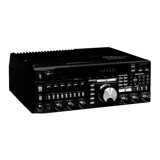
CONTENTS Page Section Page Section §1.0 SPECIFICA TIONS 4.7 Tra ter Operation: General • • • • • • • • • • • • • • • • 4.7.1 SWR Measuring & Ant. Matching 1.1 General 1.2 Transmiuer 4.7.2 Transmission 1.3 Receiver 4. - Page 3 FT-767GX ALL-MODE. ALL-BAND iRANSCEIVER The FT-7'67GX is a selld-state, ali mede synthesízed amaleur tra.nsceiver incQrpora fór up to three opttonal · ting au'. omatlc tuner; qwer supply anc;I pr tenn interoal VHF atíd UHF band model provides wat-ts power modules.
-
Page 4: Specifica Tions
FM p e r formance packet c i n and packet faci (personal tncs n supplied by Yaesu). FT-767GX. Please read rhis manual operating the y before 1. O SPECIFI CATIONS GENERAL Receivlng frequency ranges: 100 kHz to 29.99999 MHz (continuous) 50 to 53.99999 MHz... -
Page 5: Transmiuer
-35dB below peak output ±lkHz Audio output power: Micropbone impedaoce: 500 - 600 ohms 1.5W into 4 ohms With 10% THD Audlo output lmpedance: 4 to 16 ohms FT-767GX Sensitivity Cbart 100 to 0.5 to 6m• 2m• 70cm* 200 kHz 500 kHz 1.5 MHz... -
Page 6: L'l.o Controls, Switches & Connectors
2.0 CONTROLS, SWITCHES & CONNECTORS FRONT PANEL CONTROLS POWER SQL% NB The inner SQL (squelch) control sets the slg This button turns the transceiver on and off. nai threshold leve! at wbicb receiver audlo is When tbe optlonal FTS-8 muted, modes. - Page 7 MUTE (with yellow disables receiver 2-Position Pushbutton Sw!tches LED): audio, for keeping the receiver on ln VOX: automatic volce-actuaced enables standby. transmic/receive switching ln SSB, AM and (witb green LED): actlvates the nolse FM modes; semi break-in keying in CW mode; blanker.
- Page 8 (IS) FAST, MIC U/Dand KEYERpushbuttons PMS ( V / U ) Press the FAST buuon to select coarse tuning The default PMS (Prograrnmable Mernory Scan) steps for the tuning knob, PROGR AM DOWN and function sets memory channels limits for the scanner, when activated by UP keys, microphone up/down keys;...
- Page 9 fUNC (T SET) (Orange Key) AC (0) This Is the special thal actlvates The default function requires two presses (wíth one push) tbe alternate functlons of o f thls key ln succession, and cancels a li other keys. 1 f this key Is pressed clar1f1er and/or splll offsets.
- Page 11 (25) Small Controls GAIN: adjusts seositivity of 1he VOX c1rcult to audio ac the microphooe durmg voice modes, when the VOX but ton . - pressed. �-- PROC: secs the compresston leve! of the speech processor in SSB modes when the button of the sarne name Is presscd.
- Page 12 The TX GND phono Jack is connected across RX ANT Switch and Jacks contacts special transmit/receive The NOR (undepressed) switch position con relay ín the FT-767GX, which are closed nects the transceíver t o the main corui;ial circuit during transmission, open...
- Page 13 Yaesu FL- and CW semi break-in functions. Tbe ANTl-TRIP 7000 . When operating the FT-767GX wlthout control sets the levei of negative feedback linear amp, or wlth a non-QSK linear from the speaker aud10 output to the VOX amp...
- Page 14 50 ohms, unbalanced. Optimum FT-767GX POWER TRANSFORMER VOLTAGE SELECTION not match the label on the rear tbe FT-767GX, the taps on the If your local AC mains voltage d -767GX sh of tbe power transforrner the F...
- Page 15 Figure Figure 7 F•gure 9 POWER TRANSFORMER Figure Figure 4 �- ••• ••• •• c:m,, ••• ••• •• , •• Figure l 2-00V 234V 220; 117V 110\/ Figu re li Figure 6...
-
Page 16: 3.0 Inst Alla Tion
3.0 INST ALLA TION 3.3 Transceiver Location and Grounding The FT-767GX is deslgned for operacion from AC power only. The proper AC votcage is marked on the When semng u p the FT-767CX rear panei. make sure there is plenty of vent ilation around the cop and rear of the... -
Page 17: Memory Backup
Memory Backup Tuning K.nob Steps Before leavlng the factory, the lithium memory The tuning knob rate is preset by switch S3005 on the Local Unit backup system ís swítched ore. Set thís on by SkHz per revolu pushing the BACKUP switch on the rear panei tlon (Fast SOkHz/rev). -
Page 18: Opera Tion
OPERA TI ON Preset the front panei controls: This section is intended to famillarize you with the various operating reatures oí the transcei & · · · · ·· · early subsections descnbe derail ver. MlC, DRJVE ··fully countercloclcwise SQ L ll y co umerclockwise ·... -
Page 19: Mode Selection
Gen and Ham modes to receive on any between 5/50 and 10/100 kHz/revolutíon). rrequency i n the recelving range or the FT-767GX, or to transmit i n the amateur Note: LOCK swítch above and to the left or the tuning knob will disable the bands. -
Page 20: Keypad Frequency Enrry
UP/DWN Buttons on Microphone To shlft the bllnklng digit one place 10 the press the PMS (V/U) key. Notice thal The m i e buttons can be selected t o duplicate this key must be pressed to eater the hundreds either the steps of the tuning knob or of the of Mllz d igit lf the optíonal VHF or UHf band PROGRAM keys, by the setting of the MIC U/D... -
Page 21: Galn Contrai
RF AMP Switch 'B contrai is set further clockwlse the 4.6.4 blanking pulse becomes wider. This 1s useful blanking 'woodpecker' Thís swlcch (left side of lhe panei, second echoes are noL long, wider blanking from ríght) activates rccelver Rf ampli pulses also cause more of the desired signal fier, for increased... -
Page 22: If Passband Shift
1 r the heterodyne levei i s strooger than the To use t he APf, fírst tune in che deslred C W slgnal wlth the APf off, then swltch desired signal, the S-mecer indicatlon wlll and ad1ust the APf control for peak volume on dip when the notch is properly set. -
Page 23: Tra 4.7.1 Swr Measuring & Ant. Matching
General Transmitter Operation: Preset the D R I V E concrol (ou ter knob, leftmost control) fully clockwise. this point you are probably ready ouc lhe traosmnter. Recall thac valid crans Make sure the frequency is clear ( i f miulng frequenctes below MHz are only che not,... -
Page 24: Ssb Transmission
down. readjust aesu mem of battery. can also use the FT-767GX w l t h just externa! antenna luner, in which case Ali antenna luner controls are the upper TUNER panei off. - Page 25 MONI control counterclockwise effect compresslon adjustment (and • • • (smaii knob, third lo the right of the avoid unwanted dlst0rtlon). Other stations wíil hear you just as you hear yourself ( i f power switch). tbey have a good receiver) •...
-
Page 26: Cw Transmissíon
CW Transmission 4. 7 . 3 Whíle transmluing, note the indication on the ALC scale or the meter. l f the meter deflectS farther than the ALC zone reduce the DR 1 V E 767GX includes an Internai electronic Also reduce the D R I V E levei keyer, which can be used by connectlng keyer contrai settlng. -
Page 27: Rtty, Hf Packet & Sstv
UHf. Then speak into the microphone and ad 4 . 8 Programmable Tuning Steps vance the MI C gain conrrol until the meter just starts to increase on voice peaks. Different tuning (and scanning) steps can be not advance the MlC gain funher, or overmod... -
Page 28: Memory Operation
Memory Operation 4.9.2 Memory Recall ( 1 ) Ten memory channels, numbered through Press the MR key to recall memories: available for slorlng operatlng frequency and display w i l l change last mode of emlsslon selecled on a VFO. ln addl... -
Page 29: Scanní N G
4.10.2 (PMS) Now the VFO data is moved into the memory Programmable Memory Scanning channel while you can retone previously stored memory data. When you wish to recall Tbe PMS feature allows you to scan ali fre the previous VFO data, just press quencies bet wecn those stored i n two adjacent key again, and the data will be swapped again. -
Page 30: Offset Frequency Memory
4 . 1 1 . 1 Offset frequency Memory To operate split; As a further convenience for split frequency ( 1 ) Tune the displayed VFO the frequen operation, up to four offset frequencies may cy you want transmit on. be stored in special memories: one each for HF, 6m, 2m and 70cm bands (the VHF and UHF Press tbe VFO AB key once to select the... -
Page 31: Tone Squelch Operation
(and Unit fTE-2 Burst avallable for SSB operation have already been ec;! optimum p instal fT-767GX çan described, obtaining rm a çe on ín the fM silent monitoring of busy channels SSB modes requires skillful manipulation of mode, as well as for accessing repeacers re... -
Page 32: Suppressing Lnterference
l f background noise is strong enough to cause 4.13.3 Suppresslng Interference che S-meter to deflect above S-3, switch off the Rf AMP. l f the S-meter still deflects on f unwanted stations are heard near the signal noise, more than S-3, you are listening to, first make sure you have... - Page 33 Tips for CW Operatioo AGC selection is a bit more criticai when re 4.. 14 ceiving CW, and depends on the code speed: AI! o f the tips for SSB operatlon apply select the settíng that provtdes the smoothest soundlng code. equally to CW receptlon, with a few lmporcant additions.
-
Page 34: Tips For Am Broadcast Reception
4.15 for AM Broadcast Tips Reception During or ECSS reception, use the SHIFT and TONE contrais to tailor the audio of a broad The FT-767CX is ideal for serious shortwave cast as you desire. l f two AM stations are broadcasL reception - especially if you have close together you will hear a heterodyne o f... -
Page 35: Vhf Packet (F2 Mode) Operation
FT-767GX. ln this case you can connect the AFSK signai from the tnc for transmission to the PATCH IN Jack (also 600- ohm impedance), but you must also adjust the output levei for 2mVrms maximum. -
Page 36: Cat Systern Computer Contrai
Upon receiving the ACK Block, the 767 proces puter at the end of each 5-byte Command Block ses the command, and responds on the CAT SO fT-767GX is the 'opcode' that inscructs the tine (within to 20ms) with the Status Update what aetion ís... - Page 37 The rightmost column of the lnstruction Code EXAMPLE: to set 14.25000 MHz the current Chart indlcates the number of Status Update operating írequency; bytes to be expected after sendiag each com - Chart manei. Status Update accompany 14. 25000 r m a tables show t or tbese bytes: notice some parameters and rtags are carrled...
- Page 38 � � b _ UPOATE STATUS CHART rrequency digita appear in the data stream as binary-c o ded decimal (OCO: hex l indicating format of data returned by 7 6 7 ) adecimal representation of d e c i m a l d i g i t s l , w i t h leading xero- f i l l to the...
- Page 39 YA E S U E2200100 9071\-FK...
Need help?
Do you have a question about the FT-767GX and is the answer not in the manual?
Questions and answers