Table of Contents
Advertisement
Quick Links
Advertisement
Table of Contents

Related Manuals for Atlas ECS-6RM


Summary of Contents for Atlas ECS-6RM
- Page 1 ECS-6RM Owner’s Manual Sequence Controller & Monitor ECS-6RM Sequence Controller & Monitor 1601 Jack McKay Blvd. • Ennis, Texas 75119 U.S.A. Telephone: 800.876.3333 • Fax: 800.765.3435 – 1 – AtlasSound.com Specifications are subject to change without notice.
-
Page 2: Table Of Contents
ECS-6RM Owner’s Manual Sequence Controller & Monitor Table of Contents Important Safety Instructions ........................3 Introduction ............................5 ECS-6RM Key Features ......................... 6 ECM Module Key Features ........................6 Applications ............................6 Front Panel Description ........................... 7 Rear Panel Description ..........................9 Using the Output Relays ......................... -
Page 3: Important Safety Instructions
ECS-6RM Owner’s Manual Sequence Controller & Monitor Important Safety Instructions The lightning flash with arrowhead symbol within an equilateral triangle, is intended to alert the user to the presence of uninsulated “dangerous voltage “ within the product’s enclosure that may be of sufficient magnitude to constitute a risk of electric shock to persons. - Page 4 Should any of the following irregularities occur during use, immediately switch off the power, disconnect the power cord from the AC outlet and contact Atlas Sound. Do not to attempt to continue operation with the product as this may cause fire or electric shock: •...
-
Page 5: Introduction
Six Timing Sections with Remote Monitoring) modular system has been designed to meet most installation requirements for AC power distribution, equipment power conditioning and surge suppression protection. The compact 1RU unit features six sequential timing sections that can be activated at the unit or remotely. Up to three ECS-6RM units can be daisy chained together with independent trigger timing settings giving you a total of 18 sequence triggered outlets. -
Page 6: Ecs-6Rm B Key Features
Another factor would be from voltage drops in AC lines due to long transmissions. The ECS-6RM will inform you if any of these conditions occur. -
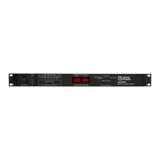
Page 7: Front Panel Description
Red “Standby” - If a Channel on an ECM-20, ECM-20M, ECM-15SH or ECM-20SH module is connected to the ECS-6RM Red LED will illuminate indicating that Channel is active and in Standby mode. If there are Channels of the ECS-6RM with no ECM modules connected, NO LED for that Channel will illuminate indicating NO CONNECTION (nC) has been established. - Page 8 These push button switches allow the selection of the Channel to be viewed at the Voltage and Current Meter. 6. Channel Selected LEDs There are six Channels in the ECS-6RM and only one Channel Voltage or Current can be viewed at a time. The Channel selected and being viewed is indicated by the illuminated LEDs.
-
Page 9: Rear Panel Description
5 conductor cable that is a minimum of 24 gauge wire. We suggest using CAT5 cable due to the common availability. Pay special attention to the port connections and DO NOT MISWIRE or damage may occur. The distance between the ECS-6RM and an ECM module can be up to 1000ft. - Page 10 Rear Panel 3. Remote Activation Connections Remote DC Voltage Trigger - The ECS-6RM can be remotely activated from hundreds of feet away using a DCV for activation. DC voltages ranging from 3V DC to 24V DC can be applied to the two terminal connections on the Remote Activation port marked “RMT V IN”...
-
Page 11: Emergency Power Down
System Control Port section below for unit daisy chain connection. Note: After changing a setting the unit power must be rest for the changed settings to take effect. 2. Delay Time Switches - The ECS-6RM has three timing settings between each sequence, 1 Second, 3 Seconds and 6 Seconds. -
Page 12: Wire And Data Considerations
Up to three units can be connected in series. Connection is via a RJ45 connector. A common Ethernet cable can be used. Note: This is not an IP Ethernet port and is only used for ECS-6RM connectivity between units. Distance between units can be several feet apart. Start with the Master Unit by connecting to the “OUT”... -
Page 13: Internal Ecm Module Features
2. G = Circuit Ground, Must be of the same circuit as the DCV source. 3. V = AC Voltage Status Signal, this signal reports back to the ECS-6RM the Incoming AC Mains Voltage to the ECM module. -
Page 14: Ap-Gnl18 - Led Gooseneck Lamp
Accessory Items AP-GNL18 - LED Gooseneck Lamp The Atlas Power AP-GNL18 is an optional Gooseneck LED Lamp and works with any of the Atlas Power 12V DC XLR base mount connectors. The length of the gooseneck is 16". ECM-15SH Standalone 15A Power Conditioner and AZ Spike Suppressor... -
Page 15: Ecm-20Sh - Standalone 20A Electrical Control Module
Remote Activation. In certain applications Atlas Sound suggests using an ECM-20 Module vs. an ECM-20M like in places where some of the features would be redundant because of the electrical location of the ECM module. There would be a cost savings to use a less expensive ECM module where redundant circuitry is not needed. -
Page 16: Ecm-Racewy6 - Ecm Raceway Housing
It may take more than one ECM-ACIN wire kit depending on many AC Mains and the distance from the AC Mains Panel. It is not necessary to use Atlas ECM-ACIN wire kit as long as the wire used is 12 gauge and UL listed. -
Page 17: Ecs-Ksw6 - Remote Key Switch And Monitor
ECS-6RM controller. A Keyed On / Off switch is provided for security. There are six Bi-Color LEDs on the ECS-KSW6 panel. One LED for each of the six sequenced channels of the ECS-6RM . These LEDs mimic the Channel Activation LEDs that are on the front of the ECS-6RM panel. - Page 18 Owner’s Manual Sequence Controller & Monitor ECM-6RM Wiring Configuration Example 1: 1 ECS-6RM unit wired to 6 ECM-20 or ECM-20M modules in the ECM-RACEWY6 housing unit, using an ECS-KSW6 for remote activation. Note: See Manual or Top Cover for Note:...
- Page 19 ECS-6RM Owner’s Manual Sequence Controller & Monitor ECM-6RM Wiring Configuration Example 3: 3 ECS-6RM units wired to 18 ECM-20 or ECM-20M modules in 3 ECM-RACEWY6 housing units. Note: See Manual or Top Cover for Note: Channel Relay Functions See Top Cover Remote Status &...
- Page 20 Status Relay CH1-6 Activates CH1-6 Example 6: Hybrid Design - 1 ECS-6RM unit wired to 5 ECM-20 or ECM-20M modules in the ECM-RACEWY6 housing unit connected to CH1-5 Trigger Voltage / Signal Status inputs, and CH6 directly controlling 1 ESC-2063 module using one trigger contact from the ECS-6RM to turn all 6 sections on at one time.
-
Page 21: Ecm-20/M Wiring Configurations
Sequence Controller & Monitor ECM-20/M Module Wiring Configuration The ECM-20/M is designed to be mated with the ECM-RACEWY6 housing and the ECS-6RM controller. The specific job install AC power requirements and power distribution layout will dictate how the ECM-20/M Modules are wired into the Raceway. Each ECM Module can be wired as a single 20A run or in a parallel configuration as illustrated below. -
Page 22: Troubleshooting
External DCV voltage is too low to activate the trigger circuit. Must be a minimum of 5VDC to activate the ECM Module. Possible short in the wiring. Issue 4 - ECM Active LED is not illuminated but the Incoming LED is. The Abnormal LED on the ECS-6RM voltage display is flashing “OL ”... - Page 23 Proper Channel is not selected for viewing. Possible Cause 5 Channel Activation LED is Illuminated Green but the Current display reads “nA” . Check the wiring between the ECS-6RM Channel and the ECM module. “V” , “A” and “D” must be in the correct polarity.
-
Page 24: Specifications
ECS-6RM Owner’s Manual Sequence Controller & Monitor Specifications Type Power Sequencer Controller Sequencer Sections Relay Sections Sequence Timing Unit Settings of 1, 3, or 6 Seconds Unit Link Power Supply External Wide Range 100V - 240VAC, UL Approval Power Consumption 0.8W... - Page 25 ECS-6RM Owner’s Manual Sequence Controller & Monitor Notes: 1601 Jack McKay Blvd. • Ennis, Texas 75119 U.S.A. Telephone: 800.876.3333 • Fax: 800.765.3435 – 25 – AtlasSound.com Specifications are subject to change without notice.
- Page 26 ECS-6RM Owner’s Manual Sequence Controller & Monitor Notes: 1601 Jack McKay Blvd. • Ennis, Texas 75119 U.S.A. Telephone: 800.876.3333 • Fax: 800.765.3435 AtlasSound.com – 26 – Specifications are subject to change without notice.
- Page 27 ECS-6RM Owner’s Manual Sequence Controller & Monitor Notes: 1601 Jack McKay Blvd. • Ennis, Texas 75119 U.S.A. Telephone: 800.876.3333 • Fax: 800.765.3435 – 27 – AtlasSound.com Specifications are subject to change without notice.
-
Page 28: Warranty
PARTICULAR PURPOSE. Atlas Sound does not assume, nor does it authorize any other person to assume or extend on its behalf, any other warranty, obligation, or liability. This warranty gives you specific legal rights and you may have other rights which vary from state to state.
Need help?
Do you have a question about the ECS-6RM and is the answer not in the manual?
Questions and answers