Advertisement
Quick Links
Atlas
ATLAS INSTALLATION MANUAL
INDEX
EQUIPMENT / MAIN FUNCTIONS
TECHNICAL FEATURES
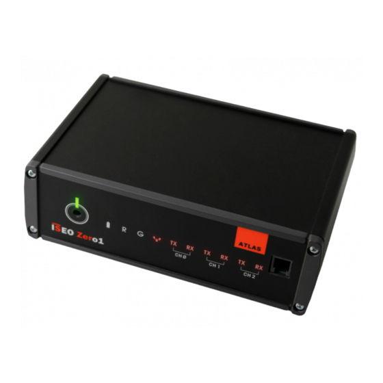
ATLAS: PIN IN/OUT / GENERAL VIEW
ATLAS: IP ADDRESS CONFIGURATION
WARNINGS
SETTING TABLES
ACTUATORS STYLOS/THESIS LINE: LOCKBUS TYPE 1 SELECTION
ATLAS: CONNECTIONS EXAMPLES
MAINTENANCE: CHARGING INTERNAL BATTERIES
1.1 DOTAZIONI
ATLAS SERVER FOR RFID AND F9000 OFF-LINE DEVICES
Package:
1 server with connectors
1 power supply
1 installation manual
1.2 MAIN FUNCTIONS
Embedded Linux server
Ethernet TCP/IP 10/100 base T connection
n. 1 Lockbus channel to connect Stylos readers and actuators (max 8+8)
n. 2 RS485 channels to connect F9000 on-line readers (max 2)
Compatible with LOCKBUS and RS485 readers and actuators
n. 2 USB Host channels (+ 1 USB channel for configuration)
n. 1 MicroSD slot
Desktop housing
Power supply 12-24Vdc
Power supply 230Vac/24Vdc 35W included
Maximum Power Consumption 10 W (no connected devices)
2. TECHNICAL FEATURES
Communication interfaces:
- 1 Ethernet interface TCP/IP 10/100 base T
- 1 LOCKBUS channel
- 2 RS485 channels
- 2 USB channels
- 1 USB channel for configuration
- 1 serial interface (debug)
Power supply:
- 12-24Vdc
- Maximum power consumption 10W
Power Supplier:
- Input 230Vac
- Output 24 Vdc 35W
- 2 poles plug
Backup batteries:
- 1500mAh battery pack
- estimated duration 30 minutes backup
CPU and memory:
- ARM 9 based CPU module
- 200MHz CPU clock (ATMEL AT91SAM9263 )
- 64MB SDRAM
- 256MB Flash
- 8GB Micro-SD
Operative system:
- Linux (Kernel 2.6.28)
Segnaling: 12 LEDs
- Power line active (green)
- Backup battery operating (yellow)
- Ethernet (orange)
- Tx/Rx channel 1 (2 orange)
- Tx/Rx channel 2 (2 orange)
- Tx/Rx channel 3 (2 orange)
- User 1 and 2 (red and green)
Product code: 5E002010
Push buttons:
- 1 reset
- 1 wake up
- 1 switch off
Housing:
- Desktop housing
- Black
- LxPxA 167x110x53 mm
Environmental characteristics:
- Operating temperature: 0°C ÷ +50°C;
- Storage temperature: -25°C ÷ +75°C.
SECTIONS
1
2
3
4
5
6
7
8
9
Advertisement

Related Manuals for Atlas ISEO ZERO1


Summary of Contents for Atlas ISEO ZERO1
- Page 1 SETTING TABLES ACTUATORS STYLOS/THESIS LINE: LOCKBUS TYPE 1 SELECTION ATLAS: CONNECTIONS EXAMPLES MAINTENANCE: CHARGING INTERNAL BATTERIES 1.1 DOTAZIONI ATLAS SERVER FOR RFID AND F9000 OFF-LINE DEVICES Product code: 5E002010 Package: 1 server with connectors 1 power supply 1 installation manual 1.2 MAIN FUNCTIONS...
- Page 2 Disconnect the main power supply of the Atlas: the LED with the battery icon turns ON (LED DL3) Hold the S3 button on the back of Atlas until the red LED "R" on the front panel turns ON (LED DL10).
- Page 3 4.1 ATLAS : IP ADDRESS CONFIGURATION Pay close attention during the new IP address configuration of the Atlas: for security reasons this device does not allow you to restore it to the “Factory settings” if not using the appropriate login credentials via web page.
- Page 4 For any technical assistance or repairs, contact only Iseo Serrature or a technical assistance centre authorised by Iseo Zero1. Iseo Zero1 reserves the right to make all of modifications that the same deems recessary to the product and the instruction manual, without prior notice, in order to improve the quality or for manufacturing and marketing necessities.
- Page 5 7.1 ACTUATORS STYLOS LINE: LOCKBUS TYPE 1 SELECTION The actuators series Stylos Line must be previously set in LOCKBUS 1 type to function properly with the Atlas Switch on the Actuator and check if red LED blinks 1 time (LOCKBUS 1) If at the power up the red LED blinks 2 times (LOCKBUS type 2) proceed as described at point 2 Switch on the Actuator keeping pressed both buttons simultaneously for 1 sec.
- Page 6 8.1 ATLAS: RFID PLANT - CONNECTION EXAMPLE (POWER SUPPLY SUPPLIED) DL11 DL10 DL12 ATLAS 6 5 4 3 2 1 4 3 2 1 4 3 2 1 3 2 1 24 VDC - 1,65 A ATLAS power supply Note: in this example the lockbus channel...
- Page 7 8.3 ATLAS: RFID PLANT - CONNECTION EXAMPLE (WITH 2 SEPARATED POWER SUPPLIES) DL11 DL10 DL12 ATLAS 6 5 4 3 2 1 4 3 2 1 4 3 2 1 3 2 1 24 VDC - 1,65 A Note: size the power supply by...
- Page 8 9. MAINTENANCE: INTERNAL BATTERY CHARGING Important: the charging cycle of the internal batteries should be performed if you have an Atlas not powered for long periods of time. In this case it is mandatory to fully charge the internal batteries at least every 3 months max.
Need help?
Do you have a question about the ISEO ZERO1 and is the answer not in the manual?
Questions and answers