
Subscribe to Our Youtube Channel
Related Manuals for Carrier BACview


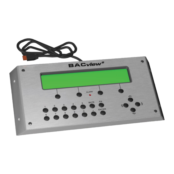
Summary of Contents for Carrier BACview
- Page 1 ® ® CARRIER CORPORATION ©2021 · Catalog No. 11-808-486-01 · 9/20/2021...
- Page 2 Verify that you have the most current version of this document from www.hvacpartners.com, the Carrier Partner Community website, or your local Carrier office. Important changes are listed in Document revision history at the end of this document. CARRIER CORPORATION ©2021. All rights reserved throughout the world. i-Vu is a registered trademark of Carrier...
-
Page 3: Table Of Contents
Wiring the BACview®6 device ......................... 15 Rnet wiring specifications ......................15 To wire the BACview®6 device ..................... 15 Wiring 2 BACview®6 devices to the Rnet ..................17 Using the BACview®6 device ........................... 17 BACview® system screens ..........................18 Setting local schedules ............................23 To set up a weekly schedule .......................... -
Page 5: Introduction
Connect... To the controller's... For... BACview®6 Handheld Local Access port Temporary user interface for start-up keypad/display device Virtual BACview® software Local Access port* Temporary user interface for start-up running on a laptop BACview®6 Rnet port Permanent user interface keypad/display device * Requires a USB Link (USB-L) These are accessory items that do not come with the controller. -
Page 6: Bacview®6 Handheld Device
BACview®6 Handheld device BACview®6 Handheld device You can use a BACview® Handheld device (part #BV6H) to start up, configure, and troubleshoot an Open controller. BACview® CARRIER CORPORATION ©2021 Installation and User Guide All rights reserved... -
Page 7: Specifications
BACview®6 Handheld device Specifications Power required +12 Vdc @ 200 mA Power supply Supplied by the 4-conductor Rnet cable from the controller. Backlit LCD display 4-line by 40-character display Cable 6 ft. (1.8 m) cable to connect to controller's Local Access port. -
Page 8: Using The Bacview®6 Handheld Device
BACview®6 Handheld device Using the BACview®6 Handheld device NOTE For information on the BACview® screens for a specific controller, see the controller's Installation and Startup Guide. For information on system screens that are common to most controllers, see BACview® system screens (page 18). -
Page 9: To Navigate
BACview®6 Handheld device To navigate To move within a screen, use the arrow keys. To jump to another screen, do one of the following: • Use the arrow keys to highlight a link, then press Enter. • Press a softkey. -
Page 10: To Obtain A Controller Status Report
To obtain a status report (Modstat) for the connected controller, press FN + . (the period key). Use the arrow keys to scroll through the report. To handle alarms If the alarm features are set up, the BACview® device will do the following when it receives an alarm from the controller: •... -
Page 11: Virtual Bacview® Application
Virtual BACview® application The Virtual BACview® application simulates the BACview® Handheld keypad/display device. Run the Virtual BACview® application on a laptop that is connected to the controller. To download the Virtual BACview® application To put the application on your laptop: Go to the website http://hvacpartners.com, then log in. -
Page 12: To Connect Your Laptop To The Controller
1 2 ft USB Link Start the Virtual BACview® application. In the Row Count field, enter the number of screen rows you want displayed (100 maximum). In the Comm Port field, select the laptop's comm port that the USB Link is connected to. To find the port number, select Start >... -
Page 13: Using The Virtual Bacview® Application
Virtual BACview® application Using the Virtual BACview® application To perform actions, you can click the keys on the Virtual BACview® interface or you can use their keyboard equivalents. Hover your cursor over a key to see its keyboard equivalent. NOTE For information on the BACview® screens for a specific controller, see the controller's Installation and Startup Guide. -
Page 14: To Navigate
Virtual BACview® application To navigate To move within a screen, click the arrow keys. To jump to another screen, do one of the following: • Click the arrow keys to highlight a link, then click Enter. • Click a softkey. -
Page 15: To Obtain A Modstat Report
To obtain a Modstat report that shows the status of the connected controller, hold down Ctrl and click . (the period key). Use the arrow keys to scroll through the report. To handle alarms If the alarm features are set up, the Virtual BACview® application does the following when it receives an alarm from the controller: •... -
Page 16: The Bacview®6 Device
You can use a BACview® device as a permanent user interface to an Open controller. You connect the BACview® device to the controller's Rnet. The BACview® device can share the Rnet with SPTor ZS sensors and a second BACview® device, with no more than 6 devices total on the Rnet. Wire the devices in a daisy-chain configuration. -
Page 17: Specifications
The BACview®6 device Specifications Power +12 Vdc @200mA supplied by the controller NOTE To use 2 BACview® devices, you must provide an external power supply for the second device. Backlit LCD display 4-line by 40-character display Protection 15 KV ESD protection to the enclosure. Built-in solid-state polyswitch protection on incoming power. -
Page 18: To Mount
BACview® device, then insert 4 screws in the holes. If mounting the BACview® device on a panel door, use the cutout in the rear mounting plate as a template to cut a hole in the panel door for the cable to pass through. -
Page 19: Wiring The Bacview®6 Device
UL: NEC CL2P, or better To wire the BACview®6 device Turn off the controller's power. Pull the screw terminal connector from the BACview® device. Partially cut, then bend and pull off the outer jacket of the Rnet cable(s). Do not nick the inner insulation. - Page 20 The BACview®6 device Insert the other 4 wires into the BACview® device's screw terminal connector. If wiring 2 cables, insert like- colored wires into each terminal. CAUTION Allow no more than .06 inch (1.5 mm) bare communication wire to protrude. If bare communication wire contacts a metal surface other than the terminal block, the sensor may not communicate correctly.
-
Page 21: Wiring 2 Bacview®6 Devices To The Rnet
Using the BACview® Handheld device (page 4). NOTE For information on the BACview® screens for a specific controller, see the controller's Installation and Startup Guide. For information on system screens that are common to most controllers, see BACview® system screens (page 18). -
Page 22: Bacview® System Screens
BACview® system screens BACview® system screens When you are viewing a controller's BACview® screens, most of the screens are specific to the controller. However, you may also see the system screens described below that are common to most controllers. For information on the controller-specific screens, see the Points/Properties appendix in the controller's Installation and Startup Guide. - Page 23 BACview® system screens Screen Description Alarm For: RTU Open, WSHP, VVT Zone, and VVT Bypass controllers Navigate to: Alarm > Alarm Displays the 100 most recent alarms received by the controller. Clock set For: RTU Open, and WSHP Navigate to: System Settings > Clockset For: i-Vu®...
- Page 24 16 = Available (Lowest priority) NOTE The value that is written from the BACview® device is always written to the controller. If a priority of 1-16 is specified, other BACnet devices must write at a priority equal to or greater than the priority specified by the BACview®...
- Page 25 BACview® system screens Screen Description Router For i-Vu® Open Router Navigate to: Router Lets you view or edit the MS/TP network number and the router's address. The [–>IP] link jumps to the following screen. For: i-Vu® Open Router Navigate to: IP Lets you view or edit network addresses.
- Page 26 BACview® system screens Screen Description BACnet For: RTU Open and WSHP Time Navigate to: System Settings > TimeMstr Master For: i-Vu® Open Router Navigate to: TimeMstr The network should have only one BACnet Time Master that issues time broadcasts. Set Time Sync Mode to: •...
-
Page 27: Setting Local Schedules
From the Home screen, navigate to CONFIG > Sched > schedule_schedule > Weekly schedule > Mon (or any day of the week), then press Enter. For help, see To navigate in a BACview® device (page 5) or To navigate in a Virtual BACview®... -
Page 28: To Set Up Exception Schedules
From the Home screen, navigate to CONFIG > Sched > schedule_schedule > Exceptions. For help, see To navigate in a BACview® device (page 5) or To navigate in a Virtual BACview® application (page 10). NOTE The screen shows any existing exceptions. To delete an exception, highlight Del, press Enter, use the INCR softkey to change the field to Yes, then press Enter. - Page 29 The 12:00 am state is always the first transition. Change the 12:00 am state if it should be On. For help, see To change a property in a BACview® device (page 5) or To change a property in the Virtual BACview®...
-
Page 30: Document Revision History
Important changes to this document are listed below. Minor changes such as typographical or formatting errors are not listed. Date Topic Change description Code* 9/20/21 The BACview®6 device Removed hybrid wiring configuration for Rnet port X-TS-AK-E * For internal use only BACview® CARRIER CORPORATION ©2021 Installation and User Guide... -
Page 31: Index
Priority levels • 17 Protection • 11 Changing a property • 4, 9 Clockset screen • 17 Connecting a BACview® device to a controller • 3, Rnet • 13 Rnet port • 1 Rnet wiring specifications • 13 Router address • 17 Daylight saving time screen •... - Page 33 CARRIER CORPORATION ©2021 · Catalog No. 11-808-486-01 · 9/20/2021...
Need help?
Do you have a question about the BACview and is the answer not in the manual?
Questions and answers