Table of Contents
Advertisement
Quick Links
45 1 1
(8182)63-90-72
(7172)727-132
(8512)99-46-04
(3852)73-04-60
(4722)40-23-64
(4832)59-03-52
(423)249-28-31
(844)278-03-48
(8172)26-41-59
(473)204-51-73
(343)384-55-89
(4932)77-34-06
(3412)26-03-58
(843)206-01-48
S I G N A L S T H E B E S T
(4012)72-03-81
(4842)92-23-67
(3842)65-04-62
(8332)68-02-04
(861)203-40-90
(391)204-63-61
(4712)77-13-04
(4742)52-20-81
(3519)55-03-13
(495)268-04-70
(8152)59-64-93
(8552)20-53-41
(831)429-08-12
(3843)20-46-81
:
pcn@nt-rt.ru
(383)227-86-73
(3812)21-46-40
(4862)44-53-42
(3532)37-68-04
(8412)22-31-16
(342)205-81-47
-
-
(863)308-18-15
(4912)46-61-64
(846)206-03-16
-
(812)309-46-40
(845)249-38-78
(8692)22-31-93
(3652)67-13-56
(4812)29-41-54
||
www.prelectronic.nt-rt.ru
,
(862)225-72-31
(8652)20-65-13
(3462)77-98-35
(4822)63-31-35
(3822)98-41-53
(4872)74-02-29
(3452)66-21-18
(8422)24-23-59
(347)229-48-12
(4212)92-98-04
(351)202-03-61
(8202)49-02-64
(4852)69-52-93
Advertisement
Table of Contents

Related Manuals for PR electronics 4511

Summary of Contents for PR electronics 4511
- Page 1 45 1 1 (8182)63-90-72 (4012)72-03-81 (862)225-72-31 (383)227-86-73 (7172)727-132 (4842)92-23-67 (8652)20-65-13 (3812)21-46-40 (8512)99-46-04 (3842)65-04-62 (3462)77-98-35 (4862)44-53-42 (3852)73-04-60 (8332)68-02-04 (3532)37-68-04 (4822)63-31-35 (4722)40-23-64 (861)203-40-90 (3822)98-41-53 (8412)22-31-16 (4832)59-03-52 (391)204-63-61 (4872)74-02-29 (342)205-81-47 (423)249-28-31 (4712)77-13-04 (3452)66-21-18 (863)308-18-15 (844)278-03-48 (4742)52-20-81 (8422)24-23-59 (4912)46-61-64 (8172)26-41-59 (3519)55-03-13 (347)229-48-12 (846)206-03-16 (473)204-51-73 (495)268-04-70 (4212)92-98-04 (812)309-46-40...
- Page 2 PR electronics A/S tilbyder et bredt program af analoge og digitale signalbehandlingsmoduler til industriel automation. Programmet består af Isolatorer, Displays, Ex-barrierer, Temperaturtransmittere, Universaltransmittere mfl. Vi har modulerne, du kan stole på i selv barske miljøer med elektrisk støj, vibrationer og temperaturudsving, og alle produkter opfylder de strengeste internationale standarder.
-
Page 3: Table Of Contents
RJ 45 Modbus connector ..................Order codes ......................Specifications ......................Approvals ........................Installation examples ................... Modbus basics ......................4511 Modbus parameter settings ..............4511 Modbus Routing diagram ............... 4511 Modbus Routing diagram (ADV SET) ..........4 51 1 V10 0 -UK... -
Page 4: Warning
General mounting, connection and disconnection of Modbus cable. Troubleshooting the device. VOLTAGE WARNING Repair of the device must be done by PR electronics A/S only. CAUTION SYMBOL IDENTIFICATION Triangle with an exclamation mark: Read the manual before installation and commissioning of the device in order to avoid incidents that could lead to personal injury or mechanical damage. -
Page 5: Safety Instructions
Only devices which are undamaged and free of moist and dust may be installed. The device may be installed and supplied by PR electronics 4000 and 9000 series only. Should there be any doubt as to the correct handling of the device, please contact your local distributor or, alternatively, PR electronics A/S. -
Page 6: Ec Declaration Of Conformity
EC DECLARATION OF CONFORMITY As manufacturer PR electronics A/S hereby declares that the following product: Type: 4511 Name: Modbus Communication Enabler is in conformity with the following directives and standards: The EMC Directive 2004/108/EC and later amendments EN 61326-1 : 2006 For specification of the acceptable EMC performance level, refer to the electrical specifications for the module. -
Page 7: Applications
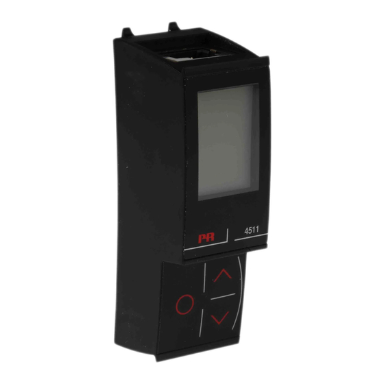
• All individual unit operating parameters can easily and quickly be configured by using the Modbus communication or by using the front display menu. • The easily readable 4511 display can be used to read the process signal, simulate the output signal, indicate sensor errors and internal module errors. Technical characteristics: • 4511 has full 4501 functionality for unit programming, process signal monitoring... -
Page 8: Mounting
MOUNTING 4511 is a detachable display that can be mounted on all system 4000/9000 fronts for programming and signal monitoring. 4511 contains a four line LCD dot display: Line 1 can e.g. show the scaled process value. Line 2 can e.g. show the selected engineering unit. -
Page 9: Order Codes
ORDER CODES 4511 = Modbus communication enabler 4590 = Configmate interface 4801 = Modbus gateway SPECIFICATIONS Environmental conditions: Specifications range ..........-20°C to +60°C Storage temperature ..........-20°C to +85°C Relative humidity............. < 95% RH (non-cond.) Protection degree ............ IP20 Installation in pollution degree 2 / overvoltage category II. -
Page 10: Approvals
Approvals: EMC 2004/108/EC ..........EN 61326-1 LVD 2006/95/EC ............EN 61010-1 UL, Standard for Safety ......... UL 61010-1 Marine: Det Norske Veritas, Ships & Offshore ..... Stand. f. Certific. No. 2.4 ATEX ................DEKRA 13ATEX0098 X II 3 G Ex nA IIC T5 Gc IECEx ................ -
Page 11: Installation Examples
4511 INSTALLATION EXAMPLES Modbus RTU 4511 4511 4511 PLC/DCS 4000 4000 4000 HMI/PC 9000 9000 9000 Gateway Safe Area Zone 2 / Cl. 1, Div. 2, gr. A-D Modbus RTU Modbus RTU 4511 4511 4511 PLC/DCS 4000 4000 4000 HMI/PC... -
Page 12: Modbus Basics
1-247 are addresses of specific devices. With the exception of broadcast messages, a slave device always responds to a Modbus message so the master knows the message was received. 4511 Supported Modbus Function Codes: Command Function code... -
Page 13: 4511 Modbus Parameter Settings
Modbus slave addressing range: 1 - 247 (247 = default address) Modbus Parameter Storage: Saved in non-volatile memory in the 4511 device (Factory Default Values are marked in bold) Modbus RTU segment line termination: A 120 Ohm resistor should be installed on both ends of a RS485 Modbus RTU segment loop to prevent signal echoes from corrupting data on the line. -
Page 14: 4511 Modbus Routing Diagram
4511 MODBUS SETTINGS ROUTING DIAGRAM 45 1 1 V1 0 0- UK... -
Page 15: 4511 Modbus Routing Diagram (Adv Set)
4511 MODBUS SETTINGS ROUTING DIAGRAM Default settings: Baud rate: 19.2 kbps Parity mode: Even Stop bit: Address: Reponse delay: 0 ms 4 51 1 V10 0 -UK... - Page 16 Displays Programmable displays with a wide selection of inputs and outputs for display of temperature, volume and weight, etc. Feature linearisation, scaling, and difference measurement functions for programming via PReset software. Ex interfaces Interfaces for analogue and digital signals as well as HART signals between sensors / I/P converters / ®...
- Page 17 (8182)63-90-72 (4012)72-03-81 (383)227-86-73 (862)225-72-31 (3812)21-46-40 (7172)727-132 (4842)92-23-67 (8652)20-65-13 (8512)99-46-04 (3842)65-04-62 (4862)44-53-42 (3462)77-98-35 (3852)73-04-60 (8332)68-02-04 (3532)37-68-04 (4822)63-31-35 (8412)22-31-16 (4722)40-23-64 (861)203-40-90 (3822)98-41-53 (4832)59-03-52 (391)204-63-61 (342)205-81-47 (4872)74-02-29 (863)308-18-15 (423)249-28-31 (4712)77-13-04 (3452)66-21-18 (4912)46-61-64 (844)278-03-48 (4742)52-20-81 (8422)24-23-59 (8172)26-41-59 (3519)55-03-13 (846)206-03-16 (347)229-48-12 (812)309-46-40 (473)204-51-73 (495)268-04-70 (4212)92-98-04 (845)249-38-78 (343)384-55-89 (8152)59-64-93...
Need help?
Do you have a question about the 4511 and is the answer not in the manual?
Questions and answers