
Subscribe to Our Youtube Channel
Related Manuals for Integra Ri3


Summary of Contents for Integra Ri3
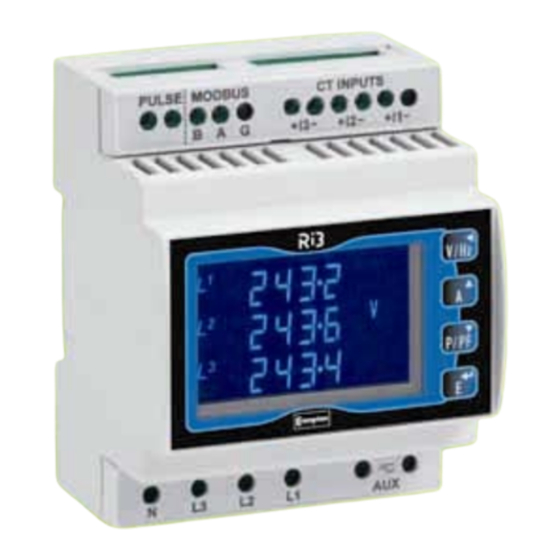
- Page 1 INTEGRA Ri3 digital metering system DIN Rail Digital Energy Meter for Single- and Three-phase Electrical Systems Installation and Operating Instructions...
- Page 2 Important safety information is contained in the Maintenance section. Familiarise yourself with this information before attempting installation or other procedures. Symbols used in this document: Risk of Danger: These instructions contain important safety information: Read them before starting installation or servicing of the equipment Caution: Risk of Electric Shock...
-
Page 3: Table Of Contents
Contents Contents Introduction Unit Characteristics ..............5 Current Transformer Primary Current ........5 RS485 Serial - Modbus™ or JC N2Protocol ......5 Pulse Output ................6 Start Up Screens Measurements Voltage and Frequency ........... 6 Current ................7 Power and Power Factor .......... - Page 4 Contents Auxiliary Supply..............22 Interfaces for External Monitoring ..........23 5.5.1 Pulse Relay Output ..............23 5.5.2 RS485 Output for Modbus™ or JC N2 Protocol....23 Reference Conditions of Influence Quantities ......24 Environment ................24 Mechanics ................24 Approval, Certification, and Standards Compliance....24 Maintenance Installation Safety ..................26 EMC Installation Requirements..........26 Case Dimensions ..............27 Wiring ..................27...
-
Page 5: Introduction
The requisite current input(s) are obtained via current transformers (CT). The Ri3 can be configured to work with a wide range of CTs, giving the unit a wide range of operation. Built-in interfaces provide pulse and RS485 Modbus™/JC N2 outputs. Configuration is password-protected. -
Page 6: Pulse Output
Measurements Pulse Output This provides a relay pulse output that clocks up measured active (Wh) or reactive (VArh) energy. The unit can produce one pulse for preset quantity of energy imported or exported. The pulse divisor and pulse width can be set from the Set-up menu as detailed in Section 0. 2 Start Up Screens The first screen lights all display segments and can be used as a display check. -
Page 7: Current
Measurements Percentage total voltage harmonic distortion (THD%) for each phase to N (not 3p3w mode) Percentage voltage THD% between phases (three phase supplies only) Current Each successive pressing of the button selects a new range: Current on each phase Neutral current (three phase supplies only) Maximum demand currents on each phase since the last Demand reset Maximum neutral demand current since the last Demand reset (three phase supplies only) Current THD% for each phase... -
Page 8: Setting Up
Setting Up 4 Setting Up To enter set-up mode, firmly press the buttons simultaneously and hold for about 5 seconds, until the password screen appears. Setting up is password-protected so you must enter the correct password (default ‘0000’) before proceeding. If an incorrect password is entered, the display reverts to measurement mode. -
Page 9: Set-Up Entry Methods
Setting Up Set-up Entry Methods Some menu items, such as password and CT, require a four-digit number entry while others, such as supply system, require selection from a number of menu options. 4.2.1 Menu Option Selection 1. Use the (up) and (down) keys to select the required item from the menu shown in Section 4.1. -
Page 10: Change Password
Setting Up Change Password Use the (up) and (down) to choose the Change Password option. Press to enter the change password routine. The New Password screen will appear with the first digit flashing. to set the first digit and press to confirm your selection. -
Page 11: Dit Demand Integration Time
Setting Up dIT Demand Integration Time This sets the period in minutes over which the Current and Power readings are integrated for maximum demand measurement. The options are Off, 5, 8, 10, 15, 20, 30, and 60 minutes. From the Set-up menu, use the (up) and (down) keys to select the dIT option. -
Page 12: Rset - Reset
Setting Up RSET - Reset Use this option to restart Energy Hours (kWh, kVArh) and/or Current/Power Demand measurements from zero. These can be set individually or all together. From the main Set-up menu, use the (up) and (down) keys to display the Reset screen. - Page 13 Setting Up Press to exit the format selection routine. SET will be removed. If you have selected N2 format, you can use the key to select the RS485 address option and set it as detailed on page 14. If you have selected ModB format, set the serial parameters as follows: Use the key to cycle through the Baud, parity, stop bits and address menu options.
- Page 14 Setting Up Press to confirm your selection. SET will be displayed. Press to exit parity setting routine. SET will go off and keys can be used to select a different Comms parameter. Stop Bits(not applicable for JC N2) Note that, if Parity is set to Odd or Even, Stop Bits will be set to 1 and cannot be changed. Use the keys to select the Stop Bits option.
-
Page 15: Pulse Output
Setting Up (not applicable for JC N2) Modbus™ Word Order This screen shows the word order (Hi/Lo) of the 8-bit bytes in the Modbus™ message format. Normal is Hi first. This setting can only be changed from the Modbus port. See the Cix Communications Guide for further information Pulse Output This option allows you to configure the pulse output. - Page 16 Setting Up Rate Use this to set the energy represented by each pulse. Rate can be set to generate 1 pulse per 0.001 = 1 Wh/VArh 0.01 = 10 Wh/VArh = 100 Wh/VArh = 1 kWh/kVArh = 10 kWh/kVArh = 100 kWh/kVArh = 1 MWh/MVArh = 10 MWh/MVArh The rate cannot be set to a value that could result in more than 2 pulses per second.
-
Page 17: Energy Units And 1% Limit
Setting Up Press to confirm your selection. The SET indicator will appear and the display will stop flashing. Press to exit Pulse Width setting routine. SET will disappear and the keys can be used to select a different Relay parameter. 4.10 Energy Units and 1% Limit Use this option to set the displayed energy units multiplier and to set a 1% limit on measured energy on or off. -
Page 18: Test
Setting Up Press to exit Units setting routine. SET will be removed. 1% Limit With the 1% Limit On, line noise below 1% of maximum power will be displayed as zero and will not accrue to the energy reading. With Limit Off, the 1% symbol will be appear on the power and energy screens to show that low power readings will be displayed and utilised. - Page 19 Setting Up Lights all LED segments so that display segments can be checked. Press to exit. Toggles display segments alternately. Press to exit. Shows the voltage and current phase sequences. Press to exit. Press to exit the selected test display mode. Press again to return to the main Set-up menu.
-
Page 20: Version Information
Setting Up Specification The display shows ‘I --‘ if a current phase is outside these parameters.] Three-phase three-wire mode Measurements are referenced from L1-L2. Voltage: For the voltage sequence test, the phase of L2-L3 relative to L1-L2 must be within the window 240 +/- 48 degrees and L3-L1 relative to L1-L2 must be within the window 120 +/- 48 degrees to record the sequence V123. -
Page 21: Specification
Specification 5 Specification Measured Parameters The unit can monitor and display the following parameters of a single phase, 3-phase 3-wire or 3- phase 4-wire supply. 5.1.1 Voltage and Frequency Phase to neutral voltages 100 to 289V a.c. (not for 3p3w supplies) Voltages between phases 173 to 500V a.c. -
Page 22: Range Of Use
Specification 5.2.1 Range of Use Values of measured quantities, components of measured quantities, and quantities which affect measurement errors to some degree, for which the product gives meaningful readings. Voltage 5 to 120% of Range Maximum (below 5% of range maximum voltage, current indication may only be approximate) Current 1 to 120% of nominal... -
Page 23: Interfaces For External Monitoring
Specification Interfaces for External Monitoring Two interfaces are provided: an RS-485 communication channel that can be programmed for Modbus™ (the default) or Johnson Controls (JC) N2 protocol a relay output indicating real-time measured energy. The Modbus configuration (Baud rate etc.) and the pulse relay output assignments (kW/kVArh, import/export etc.) are configured through the Set-up screens. -
Page 24: Reference Conditions Of Influence Quantities
Reference Conditions of Influence Quantities Influence Quantities are variables that affect measurement errors to a minor degree. Accuracy is verified under nominal value (within the specified tolerance) of these conditions. Ambient temperature 23°C ±1°C Input waveform 50 or 60Hz ±2% Input waveform Sinusoidal (distortion factor <... -
Page 25: Maintenance
Maintenance 6 Maintenance Warning During normal operation, voltages hazardous to life may be present at some of the terminals of this unit. Installation and servicing should be performed only by qualified, properly trained personnel abiding by local regulations. Ensure all supplies are de- energised before attempting connection or other procedures. -
Page 26: Installation
Installation 7 Installation The unit is intended for mounting on a standard DIN rail. Hook the unit onto the top of the rail and press the bottom of the unit until it locks in place. To remove the unit from the rail, lever down the black tab at the bottom of the unit to release it from the rail. -
Page 27: Case Dimensions
Installation The auxiliary supply to the unit should not be subject to excessive interference. In some cases, a supply line filter may be required. To protect the product against incorrect operation or permanent damage, surge transients must be controlled. It is good EMC practice to suppress transients and surges at the source. The unit has been designed to automatically recover from typical transients;... -
Page 28: Additional Considerations For Three Wire Systems
(ground) to avoid the possibility of electric shock from the neutral terminal. Auxiliary Supply The Integra Ri3 should ideally be powered from a dedicated supply; however it may be powered from the signal source providing the source will always be within tolerance for the auxiliary supply voltage range. -
Page 29: Rs485 And Modbus™ Or Jc N2 Protocol
Installation Voltage lines and auxiliary supply must be fused - see above. RS485 and Modbus™ or JC N2 Protocol The RS485 interface in conjunction with the Modbus™ or JC N2 protocol allows the unit to be interrogated and provide a response detailing the readings it has taken. This can be used for remote monitoring by a PC or SCADA system. -
Page 30: Glossary
Glossary 8 Glossary Active energy Accumulated energy (Watt hours). Current Transformer. Transforms a (usually) high current to a value that can be monitored by the meter. Firmware Software installed on a permanent medium. Johnson Controls A master - slave serial communication protocol with fixed (JC) N2 communication parameters. -
Page 31: Index
Index 9 Index 1% limit, 17, 18 Meter current, 11 Address, 14, 23 Modbus™, 5, 12, 23, 29 Auxiliary supply, 22, 28 Multiplier, 17 Baud rate, 13, 23 Noise, 17 Blue man symbol, 7 Number entry, 9 Certification, 24 Parity, 13, 23 Connections, 27 Password, 10 CT, 5, 11... - Page 32 Index While TE Connectivity (TE) has made every reasonable effort to ensure the accuracy of the information in this catalog, TE does not guarantee that it is error-free, nor does TE make any other representation, warranty or guarantee that the information is accurate, correct, reliable or current. TE reserves the right to make any adjustments to the information contained herein at any time without notice.
Need help?
Do you have a question about the Ri3 and is the answer not in the manual?
Questions and answers