
Subscribe to Our Youtube Channel
Related Manuals for Integra CALEC ST II


Summary of Contents for Integra CALEC ST II
-
Page 1: Table Of Contents
Installation and operation manual CALEC ST II ® Table of contents Safety Structure of a measuring point Scope of delivery, installation accessories Installation Controls and operation Maintenance and repair Disposal Technical specifications CE Declaration of Conformity 10 Appendix... -
Page 2: Safety
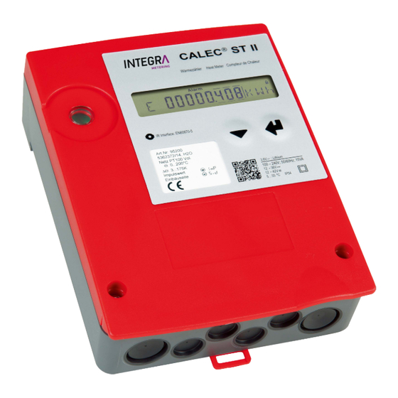
1 Safety 1.1 Intended use CALEC ST II is a high precision instrument designed for the collection, analysis, presentation and transmission ® of information. Improper or non-intended use of the device may compromise operational safety. We accept no liability for any resulting damages. 1.2 Notes on safety instructions and symbols The device has been designed to fulfil modern safety requirements. - Page 3 1.3 Installation, startup and operation General hazards and warnings WARNING! Danger of electrocution! Touching or gripping live electrical parts can cause an electric shock, which may result in burns, paralysis or death. • The device should only be opened, installed or repaired when the power has been switched off.
-
Page 4: Structure Of A Measuring Point
2 Structure of a measuring point A complete measuring point for thermal energy consists of the CALEC ST II energy calculator, paired temperature ® sensors and flow sensor. NOTE! Type of temperature sensor, pulse value, installation side! Check whether the temperature sensor type (e.g. Pt100), pulse value and installation side (cold, hot) of the flow sensor match the nameplate on the CALEC ®... -
Page 5: Scope Of Delivery, Installation Accessories
3 Scope of delivery, installation accessories NOTE! Calibrated device! The unit can be damaged if not stored correctly! This precision measuring device can be damaged by heat, moisture, dirt and vibration, which can cause malfunctions. The device must be stored in accordance with the specifications and only removed from the packaging immediately prior to installation. -
Page 6: Installation
4 Installation The CALEC ST II can be mounted on a mounting rail or on a flat wall. Suitable mounting rails are available as ® an accessory (article number 19838). Please refer to the last page of this document for a hole template for both installation types. - Page 7 Tools, assembly materials 3.5 x 0.6 Torx T15 Ø 6 3 x Ø4 3 x Ø 6 3 x 4.3 x 12 (Not included in the scope of delivery) Opening the housing CALEC ST II ®...
- Page 8 Unit design À Á Â Ã Ä The front cover can be locked into the lower section of the housing À The connection diagram is located on the inside of the front cover Á Â The motherboard can be accessed by removing the plug-in totaliser Motherboard with terminals and microswitches for configuring inputs and outputs Ã...
- Page 9 4.1 Installation Installation instructions Select the installation point: • protected from moisture, heat, direct sunlight and damage • easily accessible for reading, operation and installation • at a sufficient distance from sources of electromagnetic interference Mounting on rail DIN-EN 50222 Drill holes Ø6 À...
-
Page 10: Electrical Connection
4.2 Electrical connection Hazard warning WARNING! Danger of electrocution! Touching or gripping live electrical parts can cause an electric shock, which may result in burns, paralysis or death. • The device should only be opened, installed or repaired when the power has been switched off. - Page 11 Terminal technology The CALEC ST II is equipped with direct plug-in terminal connectors based on the “push-in” principle. Stripped ® rigid conductors or flexible conductors with crimped ferrules (AEH) can be plugged directly into the spring terminal to create a reliable, vibration-resistant and gas-tight connection. The release button has to be pressed for fine- stranded conductors, or to release the conductors.
- Page 12 Supply voltage 100 - 240 V AC 50/60 Hz Connections: L and N The supply voltage is connected via the two screw terminals in accordance with on-site regulations. The cable is passed through the diaphragm seal using the enclosed piercing awl. Voltage range: 100 - 240 V AC Frequency range:...
- Page 13 NOTE! In low voltage applications of CALEC ST II, in which a multiple grounding (PE) exists in field ® installation, the adapter “insulated supply 24V-24V» (Art. no. 80828) must be positioned upstream. Examples for grounding: • Grounded pulse input (e.g. pulser AMFLO MAG Basic) ®...
- Page 14 4-wire temperature sensor Connections: 1 to 8 Check that the temperature sensor type (e.g. Pt500) corresponds to the specifications of the CALEC ST II. ® Connection cross-sections: min. 0.22 mm Cable length: max. 100 m NOTE! Please check the connections carefully and ensure that the sensors are not reversed. terminals 1/5 and 2/6 terminals 3/7 and 4/8 cold...
- Page 15 Sensor supply voltage 24 V DC Connections: 108 and 109 Switch S4 (PS1) When switch S4 is in the left-hand position (PS1), terminals 108/109 have a 24 V DC power supply for supplying a flow transmitter, e.g. AMFLO MAG Smart. ®...
- Page 16 Flow transmitter with passive signal on pulse input #1 Connections: 10 and 11 Switch S3 (PASSIVE) When switch S3 is set to the right-hand position (PASSIVE), a flow transmitter with passive pulse signals, such as a reed relay or SSR (solid state relay), can be connected to terminals 10 and 11.
- Page 17 Flow transmitter with active signal on pulse input #1 Connections: 10 and 11 Switch S3 (ACT) Switch S3 must be moved to the left-hand position (ACT) for flow transmitters with an active signal. The pulse signal from the flow transmitter must comply with the following specifications: Voltage range: 3...48 VDC...
- Page 18 Connection examples for flow transmitters on pulse input #1 a) Connection example for TOPAS PMG/PMH flow transmitter Connections: 10 and 11 Switch S3 (PASSIVE) The TOPAS PMH transmits a passive pulsed signal when switch S3 is in the right-hand position (PASSIVE). b) Flow transmitter AMFLO SONIC UFA113 with supply ®...
- Page 19 c) AMFLO MAG Smart / MAG Basic flow transmitter with grounding (standard) ® Connections: 108, 109, 10 and 11 Switch S4 (PS1) Switch S3 (PASSIVE) Set switch S4 to the left-hand position (PS) so that the AMFLO MAG Smart is supplied ®...
- Page 20 Pulse input #2 Connections: 100 and 101 Switch S1 (in) Terminals 100 and 101 can be used as the 2nd pulse input when switch S1 is set to the right-hand position (In). The data correspond to pulse input 1 for passive pulse transmitters on terminal 10 and 11.
- Page 21 Digital output (pulse, status, alarm) #1 Connections: 100 and 101 Switch S1 (Out) Terminals 100 and 101 are used as digital output 1 when switch S1 is set to the left-hand position (Out). Switching voltage: max. 48 V DC, 36 V AC Switching current: max.
- Page 22 Module slots Connection diagram CALEC ST II is equipped with 2 separate slots for optional communication or function modules. Depending on ® the equipment fitted to the device, these 2 slots provide various connection options on outputs #1A, #1B and #2A.
- Page 23 Analogue module in socket #1 For devices with 2 analogue outputs, the analogue module is fitted to socket #1. Connections: 70, 71, 72 and 73 If an analogue module is connected to socket #1, there are 2 passive analogue outputs via terminals 70/71 (#1A) and 72/73 (#1B). The analogue outputs are electrically isolated.
- Page 24 M-Bus Modul REFERENCE! The M-Bus protocol is described in detail in a separate document, which is available on the following website: http://www.aquametro.ch/qr/prod/calec-st/11111.html M-Bus-Modul in Socket #2 Slot #2 is used for the first communication module. Connections: 24 and 25 (#2A) M-bus is connected via terminals 24 and 25 (#2A).
- Page 25 LON-Modul REFERENCE! The LON TP-FT 10 interface is described in detail in a separate document, which is available on the following website: http://www.aquametro.ch/qr/prod/calec-st/11111.html An XIF file is also available at www.lonmark.org LON module in socket #2 Slot #2 is used for the first communication module. Connections: 96a and 97b (#2A) The twisted pair wiring is via terminals 96a and 97b (# 2A) and is not poled.
- Page 26 BACnet MS/TP Modul REFERENCE! The BACnet MS/TP protocol is described in detail in a separate document, which is available on the following website: http://www.aquametro.ch/qr/prod/calec-st/11111.html The PICS document can also be found there. BACnet MS/TP module in socket #2 Slot #2 is used for the first communication module. Connections: 90a+ and 91B- (#2A) The twisted pair wiring is via terminals 90a and 91b (#2A).
- Page 27 Modbus RTU Modul REFERENCE! The Modbus RTU interface is described in detail in a separate document, which is available on the following website: http://www.aquametro.ch/qr/prod/calec-st/11111.html Modbus RTU module in socket #2 Slot #2 is used for the first communication module. Connections: 90a+ and 91b- (#2A) The twisted pair wiring is via terminals 90a+ and 91b- (#2A).
- Page 28 METASYS N2Open Modul ® REFERENCE! The METASYS N2Open Interface is described in detail in a separate ® document, which is available on the following website: http://www.aquametro.ch/qr/prod/calec-st/11111.html METASYS N2Open module in socket #2 ® For devices with a communication module, this is fitted to socket #2. Connections: 90a+ and 91b- (#2A) The twisted pair wiring is via terminals 90a and 91b (# 2A).
- Page 29 Connecting the mains voltage Hazard warning WARNING! Danger of electrocution! Touching or gripping live electrical parts can cause an electric shock, which may result in burns, paralysis or death. • The device should only be opened, installed or repaired when the power has been switched off.
- Page 30 (A) Power supply terminal (B) External isolating device (C) External protection The power supply is connected to the screw terminals (A). After tightening the terminals, check that the wires are clamped securely. Tighten the strain relief, check that it is functioning correctly. CALEC ST II ®...
- Page 31 Closing the housing Insert the cover into the hinge from above and turn to close. Tighten the two fixing screws. The screws can be secured. Once the security sealing caps stored on the top of the housing have been fitted, any unauthorised opening of the device can be detected.
-
Page 32: Controls And Operation
5 Controls and operation 5.1 Content of this manual This manual only contains details of the operating steps required to perform a function check. REFERENCE! Related documents! Related documents can be found on the following website: http://www.aquametro.ch/qr/prod/calec-st/11111.html 5.2 Controls Cover Liquid crystal display (LCD) Enter key... -
Page 33: Operating Modes
5.3 Display Places after the Service decimal point mode Flow Edit indication Alarm indication mode User mode Memory Identification 8 character decimal field Units 5.4 Operating modes The operating keys and display enable all relevant settings to be carried out without using peripheral units. The settings are arranged in three security levels (lock levels). -
Page 34: Key Functions
5.5 Key functions Keys Function Next field Higher value Accept the set value Accept the selected value Hold for longer than 1s Return to the standard “Counter” display Hold , press High-resolution display Hold , press Previous field Lower value The Service button activates Edit mode When the device is switched on, the display shows the energy reading in the Counter loop. - Page 35 5.6 Display and menu structure The following double pages shows the menu structure. Legend: Field visible Field visible under certain conditions Field in service mode grey 15% editable Field in programming mode grey 35% editable Field in Init mode white editable Note! Fields marked with * are only visible when the device has the corresponding option...
- Page 36 Menu description Display Definition Display Definition Counter Counters INFO Error messages Energy meter reading SYSt-Err Error system Volume meter reading U-Err Error supply Mass meter reading (optional) th-Error Error temperature sensor hot side Energy meter 2 reading (optional BDE/TGR) tc-Error Error temperature sensor cold side Volume meter 2 reading (optional BDE) MEM-Err...
- Page 37 Display Definition Display Definition Instant TIME Current values Time-parameters Temperature hot side Date (For cooling = Return line) Time Temperature cold side (For cooling = Supply line) Summer or Winter time Temperature difference Operating hours Power Hours of alarm Flow Hours of error Mass flow Calibration year...
- Page 38 Menu description Display Definition Display Definition Stich Billing date values LOGGEr Logger data Billing date number 1 - 12 Logger number Billing date 1 - 12 memory interval Date Date Energy meter reading Energy meter reading Volume meter reading Volume meter reading Mass meter reading Mass meter reading Energy meter reading 2,...
- Page 39 Display Definition Inputs Parameters for input signals Input number Input Function Puls value of the flow meter Installation side of the flow meter (th = hot side, tc = cold side) Maximum frequency Actual status Upper limit for th / tc alarm Lower limit for th / tc alarm Threshold for return temperature in option TGR...
- Page 40 Menu description Display Definition Display Definition Outputs Parameters for digital output signals I-Out Parameters for analogue output signals Output number Output number Output Function Output Function Type of the output Type of the output Pulse value of the output Value at 0 mA Limit 1 Value at 20 mA Limit 2...
- Page 41 CALEC ST II ®...
- Page 42 Menu description Display Definition Display Definition UnitS Units M-BuS M-Bus parameters Energy unit M-Bus number Number of decimal places on the display for energy (1 = Socket #1, 2 = Socket #2, Number of decimal places on the display for volume 3 = optical interface) Number of decimal places on the display for mass Primary M-Bus address...
- Page 43 Display Definition Display Definition ModbuS Modbus-Parameter BAcnEt BACnet-parameters Modbus number (1 = Socket #1, 2 = Socket #2) Number (1 = Socket #1, 2 = Socket #2) Modbus address Address Baud rate Mode (Master /Slave) Parity BAcnEt Device Instance Number Termination resistor ON / OFF Termination resistor ON / OFF n2-buS...
- Page 44 Menu description Display Definition Display Definition CONFIG CONFIG Type temperature sensors (PT 100 etc.) Attenuation factor for power and flow Heat carrier (medium) in option Glycol Attenuation factor for temperature Concentration of heat carrier in option Glycol Lock levels Low flow cut off Reset of alarms and counters Remanence (time of display of (depending on lock level)
- Page 45 Display Definition SYStEM Fabrication number Functionality of the calculator Date of manufacture Firmware version Hardware version Checksum CALEC ST II ®...
- Page 46 NOTE! Unit! If the option once-only on-site adjustment of the calibration-related input variables “IMP EBS” is used, ensure that the selected unit can display the amount of energy accumulated during the calibration period without counter overflow. Init-Mode: Once-only on-site adjustment Menu description Display Definition...
- Page 47 5.7 Commissioning Startup • Check the electrical connections. • Turn on the power supply. • Any error/alarms which appear must be fixed, (see Info loop and error messages). • Press the select button until the display shows “ImP”, and check the pulse value of the flow transmitter. •...
- Page 48 5.8 Error messages, alarms If a fault occurs, the message “Alarm” will appear on the display above the number pad. The optical M-Bus inter- face also flashes red to indicate the alarm message. The short message in the information loop gives details of the reason for the fault/alarm. Message Error/alarm Possible cause...
-
Page 49: Maintenance And Repair
6 Maintenance and repair 6.1 Recalibration In accordance with national legislation on weights and measures, periodic recalibration is required for devices in commercial use which are subject to mandatory verification. The recalibration interval for energy meters is usually 5 years. All calibration-related functions on the CALEC ST II can be found on the plug-in totaliser module. -
Page 50: Technical Specifications
8 Technical data The following tables contain information on the technical data of the available functions. Please refer to the price list for possible combinations. Standards CE directives 2014/32/EU Measuring Instruments Directive (MID) 2014/30/EU Electromagnetic compatibility (EMC) 2014/35/EU Low voltage (LVD) 2012/19/EU Waste Electrical and Electronic Equipment (WEEE) Directive Standards EN 1434, EN 61000-6-1, EN 61000-6-2, EN 61010, DIN 43863-5... - Page 51 Display Display units: volume , USGal Display units: energy kWh, MWh, MJ, GJ, KBTU, MBTU Data backup in the event of In EERPOM >10 years a power failure Data logger 500 values from all readings with a time stamp, stored in ring memory Logger interval: 1 min, 1 hour, 1 day, 1 week, 1 month Additional functions Adjustable low flow cut-off...
- Page 52 Pulse inputs and outputs Main input #1 Connecting a pulse generator according to NAMUR, with potential-free contact (10/11) (reed relay) or SSR (solid state relay), or for active sensors with the following values. Input passive Input active Open-circuit voltage 8 V Voltage range 3...48 V DC Short-circuit current 8 mA...
- Page 53 Option M-Bus Factory settings M-Bus Interface in accordance with EN 13757-2/-3 Addresses Primary address: 0 Secondary address: Serial number Baud rate 2400 Baud Option Modbus RTU Factory settings Physical layer and address RS 485, / address: 1 Baud rate 19200 Address range (slave) 1...247 Parity...
-
Page 54: Ce Declaration Of Conformity
9 CE Declaration of Conformity REFERENCE! CE Declaration of Conformity! The CE Declaration of Conformity is available at: http://www.aquametro.ch/qr/prod/calec-st/11111.html CALEC ST II ®... -
Page 55: Appendix
10 Appendix 10.1 Hole template CALEC ST II ®...
Need help?
Do you have a question about the CALEC ST II and is the answer not in the manual?
Questions and answers