Table of Contents
Advertisement
Quick Links
Instalation and operation
Assembly
When assembling the sauna unit, follow the dimen-
sions given in fig. 1. table 1 or the plate on the
sauna unit. The unit is attached to the wall with the
screws supplied with the unit.
- The unit may be installed in a recess with a mini-
mum height of 1900 mm. See fig.2
- Only one sauna unit may be installed in a sauna
room.
Protective railing
If a protective rail is built round the sauna unit,
please follow the instructions in fig 6.
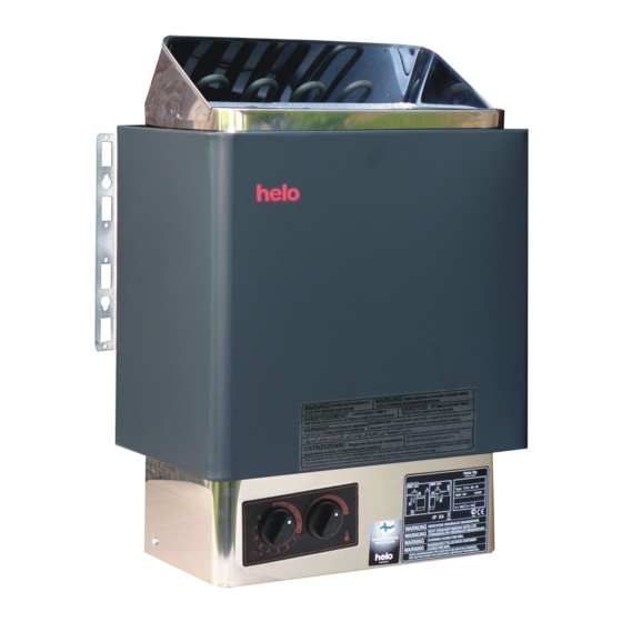
SWITCHING FOR LEFT OR RIGHT CONTROLS
The unit is supplied with a timer and thermostat
installed on the front of the unit, see fig 3. If it is
necessary to move the controls to the right or to the
left, this should be done by an qualified electrician
when the sauna is installed (see fig. 4).
1. Turn the sauna unit upside down, remove the
plate.
2. Remove the knobs (3) for the thermostat (2)
and the timer (1) by pulling them straight out.3.
Remove the screws holding the timer and ther-
mostat.
4. Remove the sectional plate from the side of the
unit.
5. Move the timer (1) and the thermostat (2) to the
side. The dial plate (5) separately packed is
mounted using the thermostat and timer mount-
ing screws.
6. Press the knobs into place.
7. Replace the sectional plate on the front of the
unit.
8. Check that all the wiring to the thermostat and
timer is intact.
9. Replace the junction box plate.
Mains connection
The sauna unit must be connected to the power
supply by a qualified electrician and in compliance
with current regulations. The unit is connected to
the power supply using suitable cable (see table
above) with REVE (or equivalent) rubber sheathed
mains lead for the final connection in the sauna.
The junction box in the sauna unit is also equipped
with a terminal block which allows the following
functions:
a) Indicator light outside the sauna room (blocks 7
och 8, see circuit diagram, fig. 7). A lead is used
with the same sectional areas as the cable to the
sauna unit (see table).
b) Electricial interlocking of another electricial
device (blocks 9 and 19, see circuit diagram 7).
A lead with a sectioal area of 1,5mm2 (6 A fuse)
is used to connect this device. A connection
box, to be mounted in the sauna room, must be
splash tight and have a condensation moisture
hole, 7 mm. The centre of this box must be not
more than 500 mm above the floor.
NOTE: The overheating safety device may have
been tripped by jolting in transport. It is reset by
pushing a screwdriver through the hole in the front
of the unit, see fig. 3.
- The wall behind the unit may not be clad with
Eternit. asbestos board or similar material. This
type of clading can cause the temperature of the
wall material to rise above the permitted level.
- Wood panelling is the approved material for walls
and ceiling in the sauna room.
i n s t a l a t i o n a n d o p e r a t i o n s a u n a t e c - p a g e 1
version 1.0-2007
Advertisement
Table of Contents

Subscribe to Our Youtube Channel
Related Manuals for Saunatec 1712-30-1718


Summary of Contents for Saunatec 1712-30-1718
- Page 1 version 1.0-2007 Instalation and operation 5. Move the timer (1) and the thermostat (2) to the side. The dial plate (5) separately packed is mounted using the thermostat and timer mount- ing screws. 6. Press the knobs into place. 7. Replace the sectional plate on the front of the unit.
- Page 2 Sauna stones tilated. Incoming air should, if possible, be led in Since they may be dusty, we recommend that they thorugh a vent immediately under the sauna unit. are rinced before being placed in the rock compar- This vent should be at least 6 cm, in diameter (see tement.
- Page 3 Distances minimums (mm) tableau 1 Pierres Brachements Sauna Minimum distance d'alimentation électrique Height Side wall Voorkant Ceiling Floor Taille de câble 5 x 2,5 5 x 2,5 i n s t a l a t i o n a n d o p e r a t i o n s a u n a t e c - p a g e 3...
- Page 4 i n s t a l a t i o n a n d o p e r a t i o n s a u n a t e c - p a g e 4...
- Page 5 Vermogen Spanning Zekering Kabeldikte 5 x 2,5 5 x 2,5 5 x 2,5 i n s t a l a t i o n a n d o p e r a t i o n s a u n a t e c - p a g e 5...
Need help?
Do you have a question about the 1712-30-1718 and is the answer not in the manual?
Questions and answers