Table of Contents
Advertisement
Quick Links
1.Overview ..................................................................................................................................................................... 3
1.1 Electrical specification ........................................................................................................................ 3
1.2 Power terminal definition ...................................................................................................................... 3
1.3 Encoder terminal definition .................................................................................................................. 3
1.4 Communication terminal definition ...................................................................................................... 3
1.5 Cooling fan terminal definition .......................................................................................................... 4
1.6 Indicator definition ................................................................................................................................ 4
1.7 KEY sets the button description .......................................................................................................... 4
1.8 Interface type ............................................................................................................................................ 4
2 Practice guide ........................................................................................................................................................ 6
2.1 UART interface ............................................................................................................................................ 7
2.2 PPM interface ............................................................................................................................................... 9
2.3 Analog interface ...................................................................................................................................... 12
3 Instruction set V1.0 .......................................................................................................................................... 14
3.1 Query drive type (ID,PING\r\n) .......................................................................................................... 15
3.2 Read the drive configuration parameters (ID,RCONFIG\r\n) ...................................................... 15
3.3 Restore factory settings (ID,FCONFIG\r\n) .................................................................................... 15
3.4 Query Help (ID,HELP\r\n) ...................................................................................................................... 15
3.5 Save all the configuration parameters (ID,EEPSAV\r\n) ............................................................ 16
3.6 Set the baud rate (ID,SBR,******\r\n) ............................................................................................ 16
3.7 Set the drive addresses (ID,SNA,***\r\n) ...................................................................................... 16
3.8 Get the number of cumulative pulse encoder (ID,GEP,*\r\n) .................................................... 16
3.9 Reset encoder cumulative number of pulses (ID,CEP,*\r\n) ...................................................... 17
3.10 Set encoder line (ID,SER,****,####\r\n) ...................................................................................... 17
3.11 Set reduction ratio (ID,SGR,****,####\r\n) ................................................................................ 17
3.12 Set direction mode (ID,SDIR,*\r\n) ................................................................................................ 17
3.13 Set the PWM signal generating method (ID,SPWM,*\r\n) ............................................................ 18
3.14 Set zero signal detection or not when start (ID,SSD,*\r\n) ................................................ 18
3.15 Gets the current rotation speed (ID,GVC,*\r\n) ........................................................................ 18
3.16 Get the maximum rotation speed (ID,GVM,*\r\n) .......................................................................... 18
3.17 Set synchronous speed (ID,SVS,*,*****\r\n) ................................................................................ 19
3.18 Set asynchronous speed (ID,SVR,*,*****\r\n) .............................................................................. 19
3.19 Perform asynchronous speed (ID,AVR,*,#\r\n) .............................................................................. 19
3.20 Get Acceleration (ID,GACC,*\r\n) .................................................................................................... 19
3.21 Get reduced speed (ID,GDEC,*\r\n) .................................................................................................. 20
3.22 Set increase or decrease speed (ID,SAD,*,*****,#####\r\n) .................................................. 20
3.23 Get the PPM Max (ID,GPA\r\n) ............................................................................................................ 20
3.24 Get the minimum PPM (ID,GPI\r\n) .................................................................................................... 20
3.25 Set PPM extreme (ID,SPPM,****,####\r\n) ...................................................................................... 20
1
Advertisement
Table of Contents

Related Manuals for DFRobot Veyron

Summary of Contents for DFRobot Veyron
-
Page 1: Table Of Contents
1.Overview ..................................3 1.1 Electrical specification ........................3 1.2 Power terminal definition ........................3 1.3 Encoder terminal definition ........................3 1.4 Communication terminal definition ...................... 3 1.5 Cooling fan terminal definition ......................4 1.6 Indicator definition ..........................4 1.7 KEY sets the button description ......................4 1.8 Interface type ............................ - Page 2 3.26 Get the control signal mode (ID,GSM\r\n) ..................21 3.27 Set the control signal mode (ID,SSM,*\r\n) ................21 3.28 Set time limit of break mode (ID,SDCT,****\r\n) ..............21 3.29 Get the PID parameter- Kp (ID,GKP,*\r\n) ..................21 3.30 Get the PID parameter- Ti (ID,GTI,*\r\n) ..................21 3.31 Get the PID parameter- Td (ID,GTD,*\r\n) ..................
-
Page 3: Overview
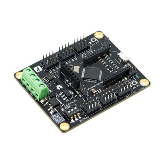
1.Overview Veyron motor drive series are the latest intelligent motor drive devices produced by DFRobot. They cover Brush DC Motor, Brushless DC Motor, Stepper Motor, etc. The Veyron 2x25A/12A is Brush DC motor drive which contains 3 intelligent interface mode: Analog Mode, PPM Mode and UART mode. -
Page 4: Cooling Fan Terminal Definition
In Analog interface mode, it is the M1 analog voltage input In PPM interface mode, it is the M1 PWM signal input In UART interface mode, it is the drive “Rx” In Analog interface mode, it is the M2 analog voltage input In PPM interface mode, it is the M2 input signal pulse width In UART interface mode, it is the drive “Tx”... - Page 5 microcontroller.. UART: support 10 commonly used baud rate, compatible with both 3.3V and 5V systems. 1.9 Control mode Open-loop speed control mode: this mode applies to the open-loop motor control mode (without encoder), the motor speed is based on the control variable. Closed-loop speed control mode: this mode applies to the closed-loop motor control (with encoder).
-
Page 6: Practice Guide
than 40℃ and less than the limit temperature, the drive automatically open the radiator until the temperature dropped below 35℃. When the internal temperature exceeds the limit temperature, fault led (Error) will be on, and the drive will go into fault mode. In PPM and UART mode, you could set it to be the discontinuous mode via the “SSM”... -
Page 7: Uart Interface
Parameters Of Motor1 Reduction Gear Ratio : 1.00 Encoder Resolution : 1 Maximum Velocity : 1000 Velocity Mode : Unloop Acceleration : 100 Deceleration : 100 PID_Kp : 0.000 PID_Ti : 0 PID_Td : 0 Parameters Of Motor2 Reduction Gear Ratio : 1.00 Encoder Resolution : 1 Maximum Velocity : 1000 Velocity Mode : Unloop... - Page 8 Open-loop control mode Connect the cable, as shown in the figure (of course, connect one circle if you only need one motor): In UART open loop control mode, the parameters associated with the actual control are as follows: baud rate, drive address, PWM signal generating method, synchronous speed, asynchronously speed, perform asynchronous speed, acceleration, deceleration, control signal mode, break mode time limit, the maximum permissible continuous current, the maximum permissible peak current limit, the maximum allowable temperature and voltage.
-
Page 9: Ppm Interface
drive detects encoder signal, A/B phase sequence of coding device will adapted automatically, then PID auto-tuning will start on M1, M1 gradually runs stably, then it completes PID parameter auto-tuning of M1. After that, it’s the PID parameter auto-tuning of M2. 4 Drive automatically reset, enter the default UART mode. - Page 10 the PPM interface, any other configuration parameters can not be set directly apart from PPM extreme, if you do need to set up the relevant parameters, you must configure them by using UART interface. All the fault messages, it should be checked with above table 1.10 “Protection”. In addition, both in open-loop or closed-loop control mode, the relationship between PPM signal and motor speed are described as the figure below (Note: when the signal is below the minimum limit value or over the maximum limit value, the drive will not respond).
- Page 11 the maximum permissible peak current limit, the maximum allowable temperature and voltage. Please refer to instruction set, set those depending on the configuration needs, when the configuration is completed, you can send directives to control the motor. Close-loop control mode Connect the cable, as shown in the figure (Connect one circle if you only control one motor): In PPM close loop control mode, the parameters associated with the actual control are as follows: encoder lines, gear ratio, direction mode, PWM signal generating method, Starting zero signal...
-
Page 12: Analog Interface
2.3 Analog interface Analog interface mode is the simplest interface, and it is often used to be tested whether drive circuit is good or not. Compared to above two interfaces, there is only one detail need to be noted, if the user is using a potentiometer to regulate motor speed, the direction mode is bidirectional, and require potentiometer mechanical location highly symmetric (that is in the mechanical rotating range potentiometer could reach, a half for positive running, another half opposite-direction running), then... - Page 13 In UART open loop control mode, the parameters associated with the actual control are as follows: direction mode, PWM signal generating method, Starting zero signal detection, control signal mode, discontinuous mode time limit, the maximum permissible continuous current, the maximum permissible peak current limit, the maximum allowable temperature and voltage.
-
Page 14: Instruction Set V1.0
In Analog close loop control mode, the parameters associated with the actual control are as follows: encoder lines, gear ratio, direction mode, PWM signal generating method, Starting zero signal detection, control signal mode, Discontinuous mode time limit, PID parameters the maximum permissible continuous current, the maximum permissible peak current limit, the maximum allowable temperature and voltage. -
Page 15: Query Drive Type (Id,Ping\R\N)
3.1 Query drive type (ID,PING\r\n) The type of Veyron motor drive series can be accessed through this command, such as: send the command to brush DC motor drive, it returns "BDC\r\n". -
Page 16: Save All The Configuration Parameters (Id,Eepsav\R\N)
* Send: 1,HELP\r\n * Returns: (wiki addresses of the DFRobot products) 3.5 Save all the configuration parameters (ID,EEPSAV\r\n) Via this instruction, you could save the current configuration parameters, before saving, it’s better to use the "read drive configuration parameter"... -
Page 17: Reset Encoder Cumulative Number Of Pulses (Id,Cep,*\R\N)
3.9 Reset encoder cumulative number of pulses (ID,CEP,*\r\n) The instruction specifies a way to reset encoder cumulative number of pulses to zero of one motor. For example, to reset encoder cumulative number of pulses to zero of M1 * Send: 1,CEP,1\r\n * Returns: none 3.10 Set encoder line (ID,SER,****,####\r\n) By setting this directive, it can be applied to two motors (M1/M2) encoder line, note: when you set... -
Page 18: Set The Pwm Signal Generating Method (Id,Spwm,*\R\N)
3.13 Set the PWM signal generating method (ID,SPWM,*\r\n) There are two independent N-MOSFET full bridge drive circuits, MOSFET gate drive signals of most drives cannot be set by user, in order to meet the needs of some users, we set three modes which can be selected, corresponding relationship between PWM generation and configuration parameters are as follows: 0:Hpwm-Lon 1:Hpwm-Lpwm (on-off) 2:Hpwm-Lpwm (on-off-on, the factory default value) -
Page 19: Set Synchronous Speed (Id,Svs,*,*****\R\N)
for quantifying is fixed at 1000. Such as accessing to M1 of maximum speed * Send: 1,GVM,1\r\n * Returns: (the maximum speed of the motor, the road) 3.17 Set synchronous speed (ID,SVS,*,*****\r\n) Synchronous speed refers to the speed once you have set, the drive will immediately regulate motor speed according to the parameters, aware that synchronous speed should not exceed the maximum speed, otherwise the drive will not respond to this command. -
Page 20: Get Reduced Speed (Id,Gdec,*\R\N)
velocity changing is the acceleration values, but not like other regular drives which changes the absolute value of the rate of deceleration slowing to 0, then accelerate up to the value of target velocity when the direction changes. For example, to access to the M1 acceleration * Send: 1,GACC,1\r\n * Returns: (the motor acceleration) 3.21 Get reduced speed (ID,GDEC,*\r\n) -
Page 21: Get The Control Signal Mode (Id,Gsm\R\N)
maximum, the specific method will be introduced in PPM interface. Second: user can reset PPM maximum in UART interface. Regardless of which method, all PPM minimum value must be guaranteed not less than 500us,the maximum PPM value is less than 2500us. For example, to set PPM control signals of the drive the minimum and maximum value respectively for 1000us and 2000us * Send: 1,SPPM,1000,2000\r\n... -
Page 22: Get The Pid Parameter- Td (Id,Gtd,*\R\N)
For example, to get the parameter of M1 velocity loop PID- Ti * Send: 1,GTI,1\r\n * Returns: (current Ti values M1) 3.31 Get the PID parameter- Td (ID,GTD,*\r\n) For example, to get the parameter of M1 velocity loop PID- Td * Send: 1,GTD,1\r\n * Returns: (the current Td values M1) 3.32 Set the PID parameters (ID,SPID,*,*******,##,&&\r\n) -
Page 23: To Set The Maximum Permissible Continuous Current And Maximum Permissible Peak Current
Such as access to M1 current current * Send: 1,GCC,1\r\n * Returns: (M1 current, unit is mA) 3.36 To set the maximum permissible continuous current and maximum permissible peak current (ID,SMLC,*****,#####\r\n) The maximum permissible continuous current should not exceed 25000, maximum permissible peak current shall not exceed 30000. -
Page 24: To Set The Limit Voltage (Id,Slv,***,###\R\N)
If when the system voltage exceeds the limit voltage range, the motor will stop and then indicates the under-voltage or over-voltage fault. * Send: 1,GSV\r\n * Returns: (the current *10 system voltage at a resolution of 0.1V) 3.41 To set the limit voltage (ID,SLV,***,###\r\n) The recommended voltage DC drive range 12~36V, limit setting value should not be less than 6V, upper limit value is not greater than 40V, otherwise the drive will not respond. -
Page 25: Clear All Fault Messages (Id,Cer\R\N)
* Send: 1,GER\r\n * Returns: (fault information, such as return of 2, then indicates the undervoltage protection) 3.43 Clear all fault messages (ID,CER\r\n) After the failure, the drive goes into protection mode, the motor will not be able to drive. In the UART interface, it can be in normal mode by clearing the fault information;... - Page 26 This product is designed for the civilian market, for the risks and losses caused by using product in medical, life support, aerospace, military and other industry which is closely linked with the life, DFRobot does not assume any legal liability.
- Page 27 E-mail. And all costs should be assumed by the customer. • We are not able to process returns for items purchased from a DFRobot distributor. Please contact the store you originally purchased from to arrange a return. Paid repair:...
Need help?
Do you have a question about the Veyron and is the answer not in the manual?
Questions and answers