Table of Contents
Advertisement
Quick Links
Instruction manual supplement
Ex/ATEX products
Covers HBSO, HBSR, HBSC2, HBLC, HBLT, HBLS and HBX
Introduction
The sensors and switches designed for hazardous areas all use a two-wire connection. This means
the output will be 4-20 mA and the output will normally pass through a barrier before it is
connected to a PLC. For level sensors normally providing an analog output will still be a 4-20 mA
signal linear to the measurement. For level switches the output will be 4 mA representing off and
20 mA representing on.
The sensors and switches can be setup like normal products but when in operation only pin 1 and
4 will be in operation.
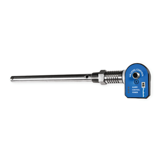
Calibration can be done using the HB-tool like normal sensors or the "R" button can be used inside
the hazardous zone where you cannot bring a PC.
Instruction manual Ex/ATEX products-02
July 2021
1 / 6
Advertisement
Table of Contents

Related Manuals for HB Products Covers HBSO


Summary of Contents for HB Products Covers HBSO
- Page 1 Instruction manual supplement Ex/ATEX products Covers HBSO, HBSR, HBSC2, HBLC, HBLT, HBLS and HBX Introduction The sensors and switches designed for hazardous areas all use a two-wire connection. This means the output will be 4-20 mA and the output will normally pass through a barrier before it is connected to a PLC.
- Page 2 Safety instruction • Danger of explosion caused by electrostatic charge! If there is a sudden discharge from electrostatically charged devices or persons, there is a danger of explosion in the Ex-area. o Take appropriate measures to prevent electrostatic charges in the Ex-area. o Clean the device surface by gently wiping it with a damp or antistatic cloth.
- Page 3 Technical data Supply voltage and load: The temperature class is: T1..T6 12-28V DC 2 Wire sensors IP-class: The IP class is: IP66 Current draw: Max 20 mA Ambient temperature range: Signal output: 4-20 mA Marking Ambient Temperature on temperature range PT1000 (measuring on the electronic cable, rod)
- Page 4 Approvals IECEx and ATEX IEC 60079-0:2017 IEC 60079-11:2011 EMC Test EMC Emission EN61000-3-2 EMC Immunity EN61000-4-2 Vibration resistance: IEC 68-2-6, 10g, 10 to 2000Hz Environmental test, incl. Damp heat cyclic, Low storage temperature, Sinus vibration, Shock test, Dry heat test, and Cooling test.
- Page 5 LED indication The green LED is flashing and indicates 24 V DC supply. (normal operation mode) The yellow LED (Control) is used for calibrating using the “R” button. The red LED (Alarm) is not used. The red and green LEDs flashing indicate no connection between mechanical and electrical unit. All three LEDs are flashing when the sensor is connected to the HB tool.
- Page 6 Labeling of the electronic unit The Electronic unit has a label with a lot of information - here is a guide to the meaning. Instruction manual Ex/ATEX products-02 July 2021 6 / 6...
Need help?
Do you have a question about the Covers HBSO and is the answer not in the manual?
Questions and answers