
Related Manuals for Motorline MC52


Summary of Contents for Motorline MC52
- Page 1 MC52 USER/INSTALLER MANUAL MENU 26 27 28 29 30 v3.3 REV. 01/2022...
-
Page 2: Table Of Contents
00. CONTENT 01. SAFETY INSTRUCTIONS INDEX 01. SAFETY INSTRUCTIONS 02. THE CONTROL BOARD TECHNICAL SPECIFICATIONS LEDs CONNECTORS 03. INSTALLATION INSTALLATION MAP BASE INSTALLATION PROCESS 04. PROGRAMMING PROGRAMMING AND DELETE REMOTE CONTROLS P MENUS E MENUS 05. PROGRAMMING "P" P1 - P2 P3 - P4 P5 - P6 P7 - P8... -
Page 3: Safety Instructions
01. SAFETY INSTRUCTIONS... -
Page 4: Safety Instructions
01. SAFETY INSTRUCTIONS... -
Page 5: Technical Specifications 4A
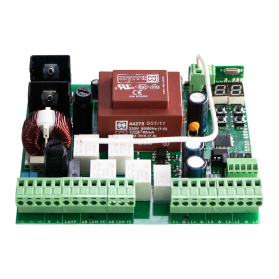
02. CONTROL BOARD 02. CONTROL BOARD TECHNICAL SPECIFICATIONS CONNECTORS The MC52 is a single-phase control board with built-in radio control system designed for the Make sure which version you are using (110Vac or 230Vac). automation of swing gates. 110V version 230V version 01 •... -
Page 6: Installation
03. INSTALLATION INSTALLATION MAP If you activate the EL option in the E5 menu, Antenna the electric lock must not be powered by the control board. To do this, use an external power supply to power the electric lock. Pushbutton or Key Selector Exterior Photocells* Interior Photocells*... -
Page 7: Programming
03. INSTALLATION 04. PROGRAMMING BASE INSTALLATION PROCESS PROGRAMMING AND DELETE REMOTE CONTROLS Remote controls programming for total opening. The installation process assumes that the gate already has mechanical or electrical limit switches installed. Remote controls programming for pedestrian opening. 01 • Connect all accessories according to the connections diagram (page 5). •... -
Page 8: P Menus 7A
04. PROGRAMMING 04. PROGRAMMING P MENUS E MENUS • We can only enter programming with the gate stopped (electrically). MAX. MIN. FACTORY MENU FUNCTION STATE PAGE PROGRAMMABLE VALUE • To access the P menu press the MENU button for 3 sec. •... - Page 9 05. PROGRAMMING "P" COURSE PROGRAMMING 05. PROGRAMMING "P" COURSE PROGRAMMING Manual programming 1 arm: You can use the remote instead of the MENU button. 01 • Press MENU for 2 sec. until appears. Whenever a leaf touches a stop, wait 1 second before clicking on the MENU. 02 •...
-
Page 10: Programming "P
PEDESTRIAN COURSE TIME 05. PROGRAMMING "P" 05. PROGRAMMING "P" PHOTOCELLS 1 PROGRAMMING Allows you to set the pedestrian course time. The default value is 10. 00 (deactivate) 00 (photocells in opening) 00 (the movement of the gate is 01 • Press MENU for 2 sec. until it appears 01 (active) 01 (photocells in closing) reversed) -
Page 11: Programming "E
05. PROGRAMMING "P" 05. PROGRAMMING "P" REMOTE PROGRAMMING OPERATING LOGIC This menu allows to set the operating logic of the automation. This menu allows you to enable/disable remote programming. 01 • Press MENU for 2 sec. until it appears 02 • Use UP until appears Automatic Mode Step by step mode Condominium Mode... - Page 12 06. PROGRAMMING "E" 06. PROGRAMMING "E" SOFT START COURSE TIME ADJUSTMENT Enables or disables the soft start. With the soft start function activated, at each start of move- It allows to adjust the working time for the opening and closing courses of the two leafs. ment the control board will control the motor start, increasing the speed gradually in the first Leaf 1 second of operation.
- Page 13 06. PROGRAMMING "E" BRAKE/LOCK/PUSH 06. PROGRAMMING "E" MANUEVERS COUNTER 01 • Press MENU for 10 sec. until it appears 02 • Use UP until appears 03 • Press Menu will appear . Use UP or DW to navigate the parameters. display flashes display flashes 04 •...
-
Page 14: Display
07. DISPLAY 08. COMPONENTS TEST DISPLAY INDICATIONS 230V/110V MOTOR To detect if the problem is in the control board or in the motor, sometimes it's necessary to IN STOP POSITION, FULLY OPENED conduct tests with a direct connection to a 230V/110V power supply. For this, it's necessary to interpose a capacitor on the connection so that the motor can work IN STOP POSITION, MIDDLE POSITION (check the capacitor type to be used in the product's manual). -
Page 15: Troubleshooting
(see page 11B). technical services for diagnosis; technical services for diagnosis. problem, disconnect motors All control boards MOTORLINE have LEDs that A) SECURITY SYSTEMS: B) START SYSTEMS: easily allow to conclude which devices are 1 • Check if there is any with anomalies.
Need help?
Do you have a question about the MC52 and is the answer not in the manual?
Questions and answers