Table of Contents
Advertisement
CONTENTS
SAFETY CONSIDERATIONS . . . . . . . . . . . . . . . . . 1-12
General . . . . . . . . . . . . . . . . . . . . . . . . . . . . . . . . . . . . . . 1
Receiving And Installation . . . . . . . . . . . 13-26
Step 1 — Check Equipment . . . . . . . . . . . . . . . . . . 13
• IDENTIFY UNIT
• INSPECT SHIPMENT
Step 2 — Provide Unit Support . . . . . . . . . . . . . . 13
• ROOF CURB
• SLAB MOUNT
Step 3 — Provide Clearances . . . . . . . . . . . . . . . . 13
Step 4 — Rig and Place Unit . . . . . . . . . . . . . . . . . 13
• UNITS WITHOUT BASE RAILS
• UNITS WITH OPTIONAL BASE RAILS
Step 5 — Select and Install Ductwork . . . . . . . . 16
• CONVERTING HORIZONTAL DISCHARGE
UNITS TO DOWNFLOW (VERTICAL) DISCHARGE
— STD (NON-ICM) UNITS
• CONVERTING HORIZONTAL DISCHARGE UNITS
— ICM UNITS
• ACCESSORY DUCT FLANGE KIT INSTALLATION
Step 6 — Provide for Condensate Disposal . . . 20
Step 7 — Install Electrical Connections . . . . . . 21
• HIGH-VOLTAGE CONNECTIONS
• ROUTING POWER LEADS INTO UNIT
• CONNECTING GROUND LEAD TO
WIRE-BINDING SCREW
• ROUTING CONTROL POWER WIRES — STD
NON-ICM UNITS (24 V)
• ROUTING CONTROL POWER WIRES — ICM
UNITS (24 V)
• SPECIAL PROCEDURES FOR 208-V
OPERATION
Pre-Start-Up . . . . . . . . . . . . . . . . . . . . . . . . . . . . 26,27
START-UP . . . . . . . . . . . . . . . . . . . . . . . . . . . . . . . . 27-39
Check For Refrigerant Leaks . . . . . . . . . . . . . . . . . 27
Start-Up Cooling Section and
Make Adjustments . . . . . . . . . . . . . . . . . . . . . . . . 27
Maintenance . . . . . . . . . . . . . . . . . . . . . . . . . . . . 40,41
Air Filter . . . . . . . . . . . . . . . . . . . . . . . . . . . . . . . . . . . . 40
Unit Top Removal . . . . . . . . . . . . . . . . . . . . . . . . . . . 40
Evaporator Blower And Motor . . . . . . . . . . . . . . . . 40
Condenser Coil, Evaporator Coil,
and Condensate Drain Pan . . . . . . . . . . . . . . . . 41
Condenser Fan . . . . . . . . . . . . . . . . . . . . . . . . . . . . . 41
Electrical Controls And Wiring . . . . . . . . . . . . . . . 41
Refrigerant Circuit . . . . . . . . . . . . . . . . . . . . . . . . . . 41
Evaporator Airflow . . . . . . . . . . . . . . . . . . . . . . . . . . 41
Metering Devices . . . . . . . . . . . . . . . . . . . . . . . . . . . 41
Liquid Line Strainer . . . . . . . . . . . . . . . . . . . . . . . . . 41
Troubleshooting Cooling Chart . . . . . 42,43
Start-Up Checklist . . . . . . . . . . . . . . . . . . . . . CL-1
Manufacturer reserves the right to discontinue, or change at any time, specifications or designs without notice and without incurring obligations.
Book 1 4
PC 111
Tab
1b 6b
Installation, Start-Up and
Service Instructions
Page
Catalog No. 535-022
Printed in U.S.A.
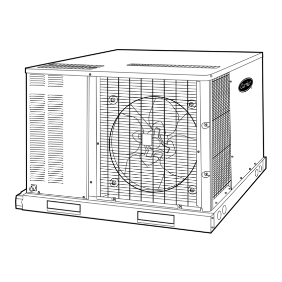
Single-Package Cooling Units
Fig. 1 — Unit 50SX With Optional Base Rail Shown
NOTE TO INSTALLER — Before the installation, READ
THESE INSTRUCTIONS CAREFULLY AND COM-
PLETELY. Also, make sure the Owner's Manual and Serv-
ice Instructions are left with the unit after installation.
SAFETY CONSIDERATIONS
Installation and servicing of air-conditioning equipment
can be hazardous due to system pressure and electrical com-
ponents. Only trained and qualified personnel should install,
repair, or service air-conditioning equipment.
Untrained personnel can perform basic maintenance func-
tions of cleaning coils and filters. All other operations should
be performed by trained service personnel. When working
on air-conditioning equipment, observe precautions in the
literature, tags and labels attached to the unit, and other safety
precautions that may apply.
Follow all safety codes. Wear safety glasses and work gloves.
Use quenching cloth for unbrazing operations. Have fire ex-
tinguisher available for all brazing operations.
Before performing service or maintenance operations on
system, turn off main power to unit. Turn off accessory
heater power switch if applicable. Electrical shock can
cause personal injury.
General —
50SS,SX cooling units are fully self-contained
and designed for outdoor installation. See Fig. 1. As shown
in Fig. 2-9, both small- and large-cabinet units are shipped
in a horizontal-discharge configuration for installation on
a ground-level slab. All units can be converted to down-
flow discharge configurations for rooftop applications. See
Fig. 10 for roof curb dimensions.
Instructions continued on page 13.
Form 50SS,SX-4SI
Pg 1
50SS018-060
50SX024-060
5-95
Replaces: 50SS,SX-3SI
Advertisement
Table of Contents
Troubleshooting

Related Manuals for Carrier 50SS018-060


Summary of Contents for Carrier 50SS018-060
- Page 1 All units can be converted to down- flow discharge configurations for rooftop applications. See Fig. 10 for roof curb dimensions. Printed in U.S.A. Form 50SS,SX-4SI 50SS018-060 50SX024-060 Instructions continued on page 13. Pg 1 5-95 Replaces: 50SS,SX-3SI...
- Page 2 REQUIRED CLEARANCES TO COMBUSTIBLE MATERIAL — in. (mm) Unit Top ....... . 14 (356) Duct Side of Unit .
- Page 3 REQUIRED CLEARANCES TO COMBUSTIBLE MATERIAL — in. (mm) Unit Top ....... . 14 (356) Duct Side of Unit .
- Page 4 REQUIRED CLEARANCES TO COMBUSTIBLE MATERIAL — in. (mm) Unit Top ........14 (356) Duct Side of Unit .
- Page 5 REQUIRED CLEARANCES TO COMBUSTIBLE MATERIAL — in. (mm) Unit Top ........14 (356) Duct Side of Unit .
- Page 6 REQUIRED CLEARANCES TO COMBUSTIBLE MATERIAL — in. (mm) Unit Top ....... . 14 (356) Duct Side of Unit .
- Page 7 REQUIRED CLEARANCES TO COMBUSTIBLE MATERIAL — in. (mm) Unit Top ....... . 14 (356) Duct Side of Unit .
- Page 8 Fig. 8 — Dimensions; Units 50SX042-060 Without Base Rail...
- Page 9 LEGEND — Center of Gravity COND — Condenser REQ’D — Required MAT’L — Material REQUIRED CLEARANCES TO COMBUSTIBLE MATERIAL — in. (mm) Unit Top ........14 (356) Duct Side of Unit .
- Page 10 Fig. 9 — Dimensions; Units 50SX042-060 With Optional Base Rail...
- Page 11 LEGEND — Center of Gravity COND — Condenser REQ’D — Required MAT’L — Material REQUIRED CLEARANCES TO COMBUSTIBLE MATERIAL — in. (mm) Unit Top ........14 (356) Duct Side of Unit .
- Page 12 PART NUMBER CPRFCURB001A00 FLAT CPRFCURB002A00 CURB CPRFCURB003A00 NOTES: 1. Roof curb must be set up for unit being installed. 2. Seal strip must be applied as required for unit being installed. 3. Dimensions in [ ] are in millimeters. 4. Roof curb is made of 16 gage steel. 5.
-
Page 13: Step 1 — Check Equipment
Manufacturer is not re- sponsible for any damage incurred in transit. Check all items against shipping list. Immediately notify the nearest Carrier Air Conditioning office if any item is missing. To prevent loss or damage, leave all parts in original pack- ages until installation. - Page 14 NOTICE TO RIGGERS Hook rigging shackles through holes in lifting brackets, as shown in Detail ‘‘A,’’ lifting brackets to be centered around the unit center of gravity. Use wood top skid when rigging, to prevent rigging straps from damaging unit. SHIPPING WEIGHT UNIT SIZE 50SS...
- Page 15 UNIT 50SS REFRIGERANT Metering Device Charge (lb) 2.60 OPERATING WEIGHT (lb) Without Base Rails With Optional Base Rails COMPRESSOR TYPE Rotary EVAPORATOR FAN Speeds Nominal Rpm Diameter (in.) Width (in.) Nominal Airflow (Cfm) Motor Hp ⁄ EVAPORATOR COIL Rows...Fins/in. 3...15 Face Area (sq ft) 1.83 CONDENSER FAN...
- Page 16 Step 5 — Select and Install Ductwork — sign and installation of the duct system must be in accor- dance with the standards of the NFPA (National Fire Protec- tion Association) for installation of nonresidence-type air conditioning and ventilating systems, NFPA 90A or residence- type,NFPA90B;and/orlocalcodesandresidence-type,NFPA90B;...
- Page 17 ACCESS PANEL (REMOVE SCREWS) Fig. 15 — Evaporator Coil Access Panel 5. Remove indoor blower access panel (Fig. 18). 6. Disconnect evaporator-fan motor leads from evaporator- fan relay and unit contactor. Carefully disengage wire tie containing evaporator-fan motor leads from the unit control box (Fig.
- Page 18 INDOOR BLOWER ACCESS PANEL (REMOVE SCREWS) Fig. 18 — Indoor Blower Access Panel WIRE TIE CONTACTOR RELAY Fig. 19 — Fan Motor Leads Fig. 20 — Blower Shelf and Housing Fig. 21 — Basepan Insulation Over Vertical Discharge Opening Fig. 22 — Insulation and Cover Removed from Vertical Discharge Opening CONVERTING HORIZONTAL DISCHARGE UNITS TO DOWNFLOW (VERTICAL) DISCHARGE —...
- Page 19 7. Remove screws securing blower shelf to duct panel. Dis- card the blower shelf. 8. Locate lances in basepan insulation that are placed over the perimeter of the vertical discharge opening cover (Fig. 21). 9. Using a straight edge and sharp knife, cut the insulation around the perimeter of the cover.
- Page 20 Fig. 24 — Filler Bracket and Blower Shelf HORIZONTAL DUCT OPENING Fig. 25 — Housing Placed for Vertical Airflow ACCESSORY DUCT FLANGE KIT INSTALLATION — Refer to Fig. 26 for duct adapter dimensions and hole locations. 1. Mark hole locations shown in Fig. 26. 2.
-
Page 21: Step 7 — Install Electrical Connections
Fig. 27 — Condensate Trap Step 7 — Install Electrical Connections The unit cabinet must have an uninterrupted, unbroken electrical ground to minimize the possibility of personal injury if an electrical fault should occur. This ground may consist of an electrical wire connected to the unit wire-binding screw in the control compartment, or con- duit approved for electrical ground when installed in ac- cordance with NEC (National Electrical Code), ANSI/... - Page 22 MOCP — Maximum Overcurrent Protection — National Electrical Code — Rated Load Amps *Fuse or HACR Breaker. †Carrier Scroll Compressor. **Copeland Scroll Compressor. NOTES: 1. In compliance with NEC requirements for multimotor and combi- nation load equipment (refer to NEC Articles 430 and 440), the overcurrent protective device for the unit shall be fuse or HACR breaker.
- Page 23 MOCP — Maximum Overcurrent Protection — National Electrical Code — Rated Load Amps *Fuse or HACR Breaker. †Carrier Scroll Compressor. **Copeland Scroll Compressor. NOTES: 1. In compliance with NEC requirements for multimotor and combi- nation load equipment (refer to NEC Articles 430 and 440), the overcurrent protective device for the unit shall be fuse or HACR breaker.
- Page 24 ROUTING CONTROL POWER WIRES — ICM UNITS (24 v) — Remove knockout in the duct panel (see Fig. 28). Remove the rubber grommet from the installer’s packet (in- cluded with unit) and install it in the knockout opening. Route thermostat wires through grommet providing a drip loop at the panel.
- Page 25 LEGEND IFO — Indoor Fan On JW — Jumper Wire Fig. 32 — Easy Select Interface Board TRAN — Transformer Fig. 33 — Units 50SX048,060 — 208/230-1-60, Integrated Control Motor Wiring Schematic LEGEND — Contactor, Compressor — Common — Compressor Time Delay —...
- Page 26 Fig. 34 — Unit 50SX048,060 — 208/230-3-60 Integrated Control Motor Wiring Schematic PRE-START-UP Failure to observe the following warnings could result in serious personal injury: 1. Follow recognized safety practices and wear protec- tive goggles when checking or servicing refrigerant system.
-
Page 27: Check For Refrigerant Leaks
4. If the unit is equipped with a crankcase heater, start the heater 24 hours before starting the unit. To start the heater only, turn the thermostat to the OFF position and ener- gize the electrical disconnect to the unit. START-UP Use the Start-Up Checklist supplied at the end of this book, and proceed as follows:... - Page 28 c. Suction-tube temperature (F) at low-side service fitting. d. Suction (low-side) pressure (psig). 5. Using ‘‘Superheat Charging Table,’’ compare outdoor-air temperature (F db) with evaporator inlet-air temperature (F wb) to determine desired system operating superheat temperature. See Tables 5A-5I and 6A-6F. 6.
- Page 29 Table 5C — Superheat Charging Table, 50SS030 TEMP (F) AIR ENT COND 14.2 15.1 13.6 14.1 13.0 13.0 10.9 11.0 LEGEND Ewb — Entering Wet Bulb SPH — Superheat at Compressor (F) Table 5D — Superheat Charging Table, 50SS036 TEMP (F) AIR ENT COND LEGEND...
- Page 30 Table 5F — Superheat Charging Table, 50SS048 (Carrier Scroll Compressor) TEMP (F) AIR ENT COND 15.5 15.5 11.7 11.8 LEGEND Ewb — Entering Wet Bulb SPH — Superheat at Compressor (F) Table 5G — Superheat Charging Table, 50SS048 (Copeland Scroll Compressor)
- Page 31 Table 5I — Superheat Charging Table, 50SS060 (Copeland Scroll Compressor) TEMP (F) AIR ENT COND 20.1 20.1 16.5 16.5 13.0 13.0 10.9 10.9 LEGEND Ewb — Entering Wet Bulb SPH — Superheat at Compressor (F) Table 6A — Superheat Charging Table, 50SX024 TEMP (F) AIR ENT COND...
- Page 32 Table 6C — Superheat Charging Table, 50SX036 TEMP (F) AIR ENT COND 21.3 21.3 19.3 19.3 17.2 17.2 13.6 13.6 10.1 10.1 LEGEND Ewb — Entering Wet Bulb SPH — Superheat at Compressor (F) Table 6D — Superheat Charging Table, 50SX042 TEMP (F) AIR ENT COND...
- Page 33 Table 6F — Superheat Charging Table, 50SX060 TEMP (F) AIR ENT COND 20.1 20.1 16.5 16.5 13.0 13.0 10.9 10.9 LEGEND Ewb — Entering Wet Bulb SPH — Superheat at Compressor (F) Table 7 — Required Suction-Tube Temperature (F)* SUPERHEAT TEMP (F) 61.5 64.2...
- Page 34 Available Airflow (Cfm) AC/HP SIZE (BLU) — The preset factory default selection for AC/HP SIZE (air conditioner/heat pump) is set to 400 cfm/ton. The selection pins are configured for 350 cfm/ ton and 400 cfm/ton. TYPE (ORN) — The TYPE is a preset factory default se- lection.
- Page 35 SEQUENCE OF OPERATION — STD NON-ICM UNITS Cooling NOTE: With the FAN switch in the ON position, 24 v is supplied to the IFR through the G terminal on the thermo- stat. This voltage energizes the coil of the contactor, closing the normally-open set of contacts which provide continuous power to the indoor (evaporator) fan motor (IFM).
- Page 36 Table 8 — Dry Coil Air Delivery* — Horizontal Discharge (Deduct 10% for 208 v) — Unit 50SS UNIT MOTOR SIZE SPEED Watts Watts — High — Watts Watts 1025 Watts — High — Watts — — Watts — — Watts —...
- Page 37 Table 9 — Dry Coil Air Delivery* — Vertical Discharge (Deduct 10% for 208 v) — Unit 50SS UNIT MOTOR SIZE SPEED Watts Watts — High — Watts Watts 1025 Watts — High — Watts — — Watts — — Watts —...
- Page 38 Table 11 — Dry-Coil Air Delivery* — Vertical Discharge (Deduct 10% for 208 V) — Unit 50SX UNIT MOTOR SIZE SPEED DELIVERY 50SX Watts Watts 024, 1025 Watts High Watts 1375 Watts 1520 Watts High Watts 1400 Watts 1600 Watts High Watts 1050...
- Page 39 UNIT SIZE 018* *Unit 50SS only. Table 14 — Accessory Electric Heater Pressure Drop (in. wg) HEATER 5-20 0.030 UNIT FILTER SIZE SIZE 500 600 700 800 900 1000 1100 1200 1300 1400 1500 1600 1700 1800 1900 2000 2100 2200 2300 50SS (in.) 018, 024 20 x 20 0.05 0.07 0.08 0.10 0.12 0.13...
-
Page 40: Air Filter
MAINTENANCE To ensure continuing high performance, and to minimize the possibility of premature equipment failure, periodic main- tenance must be performed on this equipment. This cooling unit should be inspected at least once each year by a quali- fied service person. To troubleshoot cooling of units, refer to Troubleshooting chart in back of book. -
Page 41: And Condensate Drain Pan
c. Lift wheel from housing. When handling and/or clean- ing blower wheel, be sure not to disturb balance weights (clips) on blower wheel vanes. d. Remove caked-on dirt from wheel and housing with a brush. Remove lint and/or dirt accumulations from wheel and housing with vacuum cleaner, using soft brush at- tachment. -
Page 42: Troubleshooting Cooling Chart
TROUBLESHOOTING COOLING CHART SYMPTOM Compressor and con- Power failure denser fan will not Fuse blown or circuit breaker tripped start. Defective thermostat, contactor, transformer, or control relay Insufficient line voltage Incorrect or faulty wiring Thermostat setting too high Single-phase units with scroll compressor (50SS048,060 and 50SX) have a 5-minute time delay Compressor will not Faulty wiring or loose connections in... - Page 43 TROUBLESHOOTING COOLING CHART (cont) SYMPTOM Integrated control motor (units 50SX048 208/230 v and 50SX060) IFM does not run. Integrated control motor (units 50SX048 208/230 v and 50SX060) IFM runs when it should be off. Integrated control motor (units 50SX048 208/230 v and 50SX060) IFM operation is intermittent.
- Page 46 For a free Service Training Material Catalog (STM), call 1-800-962-9212. Ordering instructions are included. Copyright 1995 Carrier Corporation Manufacturer reserves the right to discontinue, or change at any time, specifications or designs without notice and without incurring obligations. Book 1 4 PC 111 Catalog No.
- Page 48 VERIFY THAT 3-PHASE SCROLL COMPRESSOR (50SS048,060; 50SX036-060 UNITS ONLY) IS ROTATING IN CORRECT DIRECTION VERIFY REFRIGERANT CHARGE USING CHARGING CHARTS ON PAGES 28-33. Copyright 1995 Carrier Corporation Manufacturer reserves the right to discontinue, or change at any time, specifications or designs without notice and without incurring obligations. Book 1 4 PC 111 Catalog No.
Need help?
Do you have a question about the 50SS018-060 and is the answer not in the manual?
Questions and answers