Advertisement
Quick Links
Advertisement

Related Manuals for MD SPORTS BG125Y21015


Summary of Contents for MD SPORTS BG125Y21015
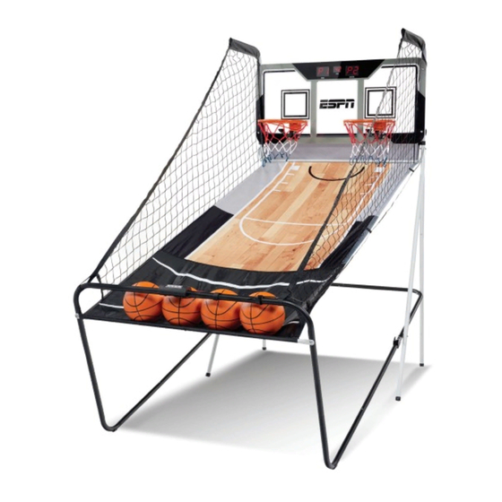
- Page 1 MODEL BG125Y21015 Target Assembly Instructions 877-472-4296 www.medalsports.com...
- Page 2 PLEASE CONTACT US BEFORE RETURNING THE PRODUCT TO THE STORE! WE ARE READY TO HELP DO NOT RETURN TO STORE Please Contact MD SPORTS Customer Service Toll Free 877-472-4296 Mon.-Fri., 9:00 a.m. to 5:00 p.m. EST For additional resources and Frequently Asked Questions, please visit us at www.medalsports.com...
-
Page 3: Tools Required
Do not use or keep area assembly area product outdoors. For indoor use only. No wet/humid conditions. WARNING Adult assembly required. CHOKING HAZARD - This item contains small parts. Not suitable for children under 3 years. BG125Y21015 (Continued on the next page) www.medalsports.com... -
Page 4: Parts Identifier
FOR FIG. 8 Electronic Scorer Paddle Sensor Control Box FOR FIG. 8 FOR FIG. 10 FOR FIG. 15 FOR FIG. 7 Rim Support Rim Net Self - Stick Strap Backboard FOR FIG. 17 Wire clip BG125Y21015 (Continued on the next page) www.medalsports.com... -
Page 5: Before Assembly
Find a clean, level place to begin the assembly of your product. Verify that you have all listed parts as shown on the part list pages. If any parts are missing, call our customer service. BG125Y21015 (Continued on the next page) - Page 6 English BEFORE ASSEMBLY Please inspect and layout all the POLES and parts ASSEMBLY FIG. 1 Pre-installed Pre-installed BG125Y21015 (Continued on the next page) www.medalsports.com...
- Page 7 English ASSEMBLY FIG. 2 Pre-installed Pre-installed FIG. 3 BG125Y21015 (Continued on the next page) www.medalsports.com...
- Page 8 English ASSEMBLY FIG. 4 BG125Y21015 (Continued on the next page) www.medalsports.com...
- Page 9 English ASSEMBLY FIG. 5 Pre-installed Punched hole BG125Y21015 (Continued on the next page) www.medalsports.com...
- Page 10 English ASSEMBLY FIG. 6 Pre-installed Pre-installed Short Long BG125Y21015 (Continued on the next page) www.medalsports.com...
- Page 11 English ASSEMBLY FIG. 7 FIG. 8 Note: Ensure that washers are used on both sides of the backboard as Note: DO NOT over tighten bolts. shown in FIG. 8. BG125Y21015 (Continued on the next page) www.medalsports.com...
- Page 12 English ASSEMBLY FIG. 9 Note: Connect Paddle Sensor (15) to the backboard. FIG. 10 Note: Attach the part with wider meshes to the rim. BG125Y21015 (Continued on the next page) www.medalsports.com...
- Page 13 (21) to the Top Tubes - 1. Note: Please do not use any bolts on the Backboard at this step. The Bolts will be added later for the Ramp Tab (See FIG. 14). BG125Y21015 (Continued on the next page) www.medalsports.com...
- Page 14 Note: To secure the Ball Return Net (13) then slide the sleeves of the Ball Return Net to Tube - 1, attach the elastic straps over (13) onto tubes at the top. the nuts. Connect Velcro Strap here. BG125Y21015 (Continued on the next page) www.medalsports.com...
- Page 15 Tube - 11, slide Tube - 12 into the sleeve of the Ball Return Net, then attach it to Tube - 11 as shown in FIG. 13. Fasten the Bolt (A3) with the Allen Key to finish this step. BG125Y21015 (Continued on the next page) www.medalsports.com...
- Page 16 Back View Back View Ramp Tab Note: At each bottom hole of thebackboard, attach the ramp tabs on Ball Return Net (13) using Bolts (A4), Washers (A1), Plastic Washers (A5) and Nuts (A7). BG125Y21015 (Continued on the next page) www.medalsports.com...
- Page 17 (20) as shown in FIG. 15. Control Wire FIG. 16 Electronic Scorer CONTROL VISITOR HOME CONTROL VISITOR HOME Control Wire Sensor wire Note: Insert the control wire and the sensor wires into the electronic scorer (14). BG125Y21015 (Continued on the next page) www.medalsports.com...
- Page 18 English ASSEMBLY FIG. 17 Wire clip Control Paddle Paddle Sensor Sensor Note: Fix the wires on both sides onto the corresponding clips. BG125Y21015 (Continued on the next page) www.medalsports.com...
- Page 19 Note: The locking pin (P3) needs to be removed from its original position when the game is being used before insertion to the new position when folded. IMPORTANT! Make sure to use the Locking Pin (P3) when folded. BG125Y21015 (Continued on the next page) www.medalsports.com...
- Page 20 Press and hold the "RESET" button for 3 seconds to reset the game. Note: If no shot is made or no button is pressed within 5 mins, the scorer will be turned off automatically. BG125Y21015 (Continued on the next page)
-
Page 21: Game Options
“PLAY” key, and so on in a similar fashion. At the end of each game, the highest score is displayed on the right; when a player’s score exceeds the highest score shown on the right, the original score will be replaced (exiting the game mode or powering off can clear the record). BG125Y21015 (Continued on the next page) www.medalsports.com... - Page 22 (1) This device may not cause harmful interference, and (2) This device must accept any interference received, including interference that may cause undesired operation. For additional resources, please contact Medal Sports Corp. 1300 Melissa Drive, Suite 124, Bentonville, AR 72712 Toll Free: 877-472-4296 BG125Y21015 (The last page) www.medalsports.com...
- Page 23 www.medalsports.com...
Need help?
Do you have a question about the BG125Y21015 and is the answer not in the manual?
Questions and answers