Table of Contents
Advertisement
Quick Links
Advertisement
Table of Contents

Subscribe to Our Youtube Channel
Related Manuals for Weaver W-987


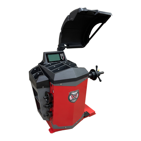
Summary of Contents for Weaver W-987
- Page 2 WHEEL BALANCER USER MANUAL...
-
Page 3: Table Of Contents
1. PREFACE ..............................1 2. INSTALLATION AND OPERATION ......................4 3. TECHNICAL PARAMETER......................... 5 4. TRANSPORTATION AND INSTALLATION ....................5 5. SAFETY AND PRECAUTIONS ........................6 6. CONFIGURATIONS ..........................7 7. INSTALLATION ............................7 8. DISPLAY PANEL AND BUTTONS ......................8 9. -
Page 4: Preface
cause minor injuries or damage to property. 1. PREFACE Read these instructions carefully before using the machine. Keep this manual and the illustrated materials supplied with the equipment in a folder near the place WARNING of operation so as to allow the machine operators to There will be one year of warranty period on the consult the documentation at any time. - Page 5 positioning them as indicated on the packaging. other persons. Do not operate the machine until you have read and understood all the danger/warning notices in this manual. The correct use of this machine requires a qualified and authorized operator. This operator must be able to All regulations in force concerning safety at work must understand the manufacturer's written instructions, be be complied with when choosing the installation...
- Page 6 serviced. - Any unauthorized changes or modifications made Grounding symbol: This decal, positioned to the machine automatically release the manufacturer on the rear left side of the machine, from any liability in the case of damage or accidents indicates where to connect the ground resulting from such changes or modifications.
-
Page 7: Installation And Operation
last 4 is company product series number. If the power system is complying with the technical What on the cross line is the name and address of the parameter marked on the nameplate of the machine. company and under the cross line not includes the The wiring of the machine must have the fuse and the above explained but the rated electrical parameters, perfect ground protection. -
Page 8: Transportation And Installation
-adopts quality computer with the feature of high intelligence and high stable -mechanical main shaft adopts high precision bearing driven, wear-resistant, low noise -press stop key to realize the emergency stop -full automatic dynamic/static balance check -balance 3 ALU rim and 1 motorcycle tire -self-calibration and full automatic trouble diagnosis 3.2 Work principal Balancing sensor tests the unbalance signal and send... -
Page 9: Safety And Precautions
and documents you purchased according to the used exclusively to measure the extent and position of car wheel unbalances, within the limits specified in the packing list. If you have any question, please contact with the dealer. Package materials such as plastic, PBV, technical data section. -
Page 10: Configurations
accidents and injuries. Environment temprature: 5~50℃; Altitude: ≤4000M; 6. CONFIGURATION Relative humidity: ≤85% If the wheel is unbalanced, there will have wheel beating and steer wheel vibration during running, Wheel balancer structure affecting the driving, resulting in the steering system to The wheel balancer includes mechanism and electric: incresase the gap and damage the shock absober and 2.1 mechanism:... -
Page 11: Display Panel And Buttons
(note: you can install a tire on the main shaft when tighten the screw and hold the tire by hand to avoid the main shaft rotating together with screw) 4. mount on the wheel Check and clean the dust and mud and if there are foreign bodies, such as metal and stone, clipped on the surface of the tire. - Page 12 balance, which is the default mode. Pull out the distance gauge against the rim edge or rim internal area where you want to adhere the balance weight (ALS1 mode, pull the distance gauge against the 2.Input wheel dimensions rim internal area, ALS2 mode, any internal area) ,read This device can automatically measure the A (or A1, A2) value of the wheel and the D (or D1, D2) value of the wheel.
- Page 13 adjustment.This method is based on a few adjustments width gauge to its home position to the rim diameter. Without manual measurement, this method is more convenient, but the results will be slightly less accurate. 3. After entering the wheel dimensions, press the START key to launch a spin of the balancing machine.
-
Page 14: Hidden Weight (Weight Split) Function
Apply the stick on weight when the weight position Balance weight application position under each mode: indicator light is on To keep the position of the wheel still, rotate the ruler, the head of the ruler on the rim, and then on the balance weight , it will be pressed on the wheel rim, pull back the ruler 5. -
Page 15: Opt Function
will be lit when the hidden weight operation can be performed). Taking ALS2 mode as an example to illustrate the operation method of the hidden weight function. In ALS2 mode, enter the values of A1, D1, A2 and D2 of the wheel, and run the balancing machine to get the (If the laser indication function is already enabled, test results. -
Page 16: Calibrations
The operation steps of setting up the equipment are as needs to be rotated 180 degrees. follows: Press F to enter set-up mode Make a mark on the axle of the balancing machine and the same position on the rim so that when the wheel is 1.100g Calibration installed again, the rim can be installed back to the 2. -
Page 17: Introduction
Press the LAR+/- key to change the b value to the width the "START" key to launch a spin of balancer value of the mounting wheel. again. 3.3 pull the ruler to the measuring position of the wheel 4.3 after the wheels stop, complete the motorcycle and place the measuring position of the wheel width adaptor calibration ruler on the outside of the wheel. -
Page 20: Error List
original position when position 14. ERROR LIST turn on the machine. Reason Solution Choose wrong spokes Choose two neighbouring encoder board damaged; 1.If shaft can rotate, when hidden the weight spokes outside power baord damaged; change encorder board; unbalance position. motor damaged. - Page 21 accidental dropping and subsequent damage that the speed of it is not too fast compared to the machine so no need to change the grease. If you note the run of Mobil grease XHP the bearing abnormal or there is noise, change the NLGI degree bearing.
- Page 22 products, or improper use of parts of them, may have Powder YES on the environment or on human health are prevented. CO2 YES Furthermore, this helps to recover, recycle and reuse many of the materials contained in these products. Electrical equipment Electrical and electronic manufacturers and distributors Water set up proper collection and treatment systems for...
- Page 23 Appendix Protective cover installation Hex. Screw M10X30 Flat washer Spring washer Spring Screw M10X20 The manufacturer has the right to modify the products without notification to the buyer in advance...
Need help?
Do you have a question about the W-987 and is the answer not in the manual?
Questions and answers