Subscribe to Our Youtube Channel
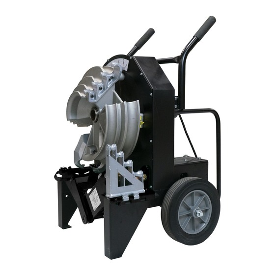
Summary of Contents for Southwire MAXIS Xtreme Bender MXB2000
- Page 1 OPERATING INSTRUCTIONS MAXIS™ Xtreme™ Bender MXB2000 Product distributed by Southwire Company,LLC One Southwire Drive, Carrollton,GA 30119 2021 Southwire Company,LLC. All rights reserved MXB2000 manual...
-
Page 2: Table Of Contents
SAFETY FIRST WARNING READ AND UNDERSTAND ALL THE INSTRUCTIONS AND Safety is essential in the use and maintenance of Southwire SAFETY INFORMATION IN THIS MANUAL BEFORE OPERAT- Equipment. This instruction manual and any placards or ING OR SERVICING THE MXB2000 markings on the bender provide information for avoiding hazards and unsafe practices related to the use of this bender. -
Page 3: Important Safety Information
WARNING – Personal Safety Hazards • Only trained and qualified persons should use the MXB2000 (Southwire Maxis™ Xtreme™ Bender) • Wear eye protection, hard hat, cut resistant gloves, and safety toe shoes when using this bender. • Do not use this bender while tired or under the influence of drugs,... -
Page 4: Grounding Instructions
GROUNDING INSTRUCTIONS DANGER – Electrical Shock Hazards – Entanglement Hazard WARNING • Do not operate this bender while wearing loose fitting clothing. Retain long hair. • Keep guards in place and in working order. • Remove any tools from the bender before operating. Form a habit of checking to see that all tools are removed from bender before turning it •... - Page 5 • Inspect the bender before use. Replace worn, damaged, or missing parts with Southwire replacement parts. A damaged or improperly FAILURE TO OBSERVE THESE WARNINGS CAN RESULT IN SEVERE assembled component could break and strike nearby personnel.
-
Page 6: Purpose Of This Manual
3. All specifications are nominal and may change as design improve- 1/2" to 2" rigid conduit and pipe ments occur. Southwire Company, LLC shall not be liable for damages resulting from misapplication or misuse of its products. Model Number: MXB2000E... - Page 7 SETUP AND OPERATION: 1. Before assembling the MXB2000, ensure that the bender is discon- EMT SHOE GROUP nected from the power source. 2. Mount the handle using the four(4) hex bolts and washers. The bolts & washers can be found in the fabric pouch hanging on the MXB2000 frame.
- Page 8 4. The IMC and EMT roller supports have a trap plate that may require 6. Install the cotter pin into the end of the roller support hinge pin to adjustment to properly fit under the leg of the bender. Verify that the secure it.
- Page 9 1. Slide the appropriate bending shoe onto the shaft of the main 3 . Use a 10-3 electrical cord with the bender (not supplied) sprocket, as shown. Align the four studs on the back of the shoe with the four holes in the main sprocket. Push the shoe in until it stops. Installing a Bending Shoe 2 .
- Page 10 BENDING CONDUIT 5. Using your foot, lift up on the pressure pedal to position the 1 ½” & Bending ½”, ¾”, 1”, and 1 ¼” EMT, Rigid, and IMC Conduit 2” roller unit into the fully retracted position. The 1 ½” and 2” rollers 1.
- Page 11 6. The bending shoe is separated into two halves. One half of the shoe is used for bending ½”, ¾”, 1”, and 1 ¼” conduit. The other half of the shoe is used for bending 1 ½” and 2” conduit. See markings cast into the center of the shoe indicating the conduit size for each half.
-
Page 12: Bending 1 ½" And 2" Emt, Imc, & Rigid Conduit
Bending 1 ½” and 2” EMT, IMC, and Rigid Conduit 10. Facing the front of the bender, load the conduit into the right side of Note: Pressure rollers are not used with Rigid conduit the bender. Place the conduit on the correct size roller and guide it into 1. -
Page 13: Adjusting The 1 ½" And 2" Pressure Rollers
Adjusting the 1 ½” & 2” Pressure Rollers 13. Before commencing with the bend, press down on the pressure Note: Pressure rollers are not used with Rigid conduit pedal with moderate pressure (approximately 30-40 lbs of force). If the pressure pedal rotates and fully engages with the stop, the When bending 1 1/2"... -
Page 14: Illustrated Bending Glossary
Illustrated Bending Glossary ARROW ADJUSTMENT The arrow on the shoe can be adjusted to compensate for variations back-to-back bend— any U-shaped bend formed by two parallel 90° in conduit. bends with a straight section of conduit or pipe between the bends. 1. -
Page 15: Bending Instructions
Bending Instructions 90° STUBS Offset Bend 1. Measure the length of the required stub. 1. Measure the height and length of the obstruction. Select the angle to 2. See the Minimum Stub Length formula on the Deduct Table. The be used. required stub must be equal to or longer than the Minimum Stub Length. -
Page 16: Specifications
Handle Removal and Replacement The handle of the MXB2000 is designed to be removable. This feature Problem Possible Remedy Probable Cause is convenient when performing complex bending and makes it easy to Check supply voltage circuit operation. No voltage. replace a damaged handle. Check that switch is on. - Page 17 WARRANTY ON Under this 1-Year Limited Warranty, Southwire Company, LLC will have no liability for any SOUTHWIRE CONTRACTOR EQUIPMENT of the following: normal wear and tear resulting from product use and damage arising What Does This Warranty Cover? out of misuse, abuse, modification, and improper product maintenance. This warranty...
- Page 18 1. All warranty claims must be approved by Southwire’s Tools & Assembled Products Warranty Department prior to return of product. If Southwire determines that a product is defective, Southwire will, at its option, repair or replace defective products or defective product components, free of charge.


Need help?
Do you have a question about the MAXIS Xtreme Bender MXB2000 and is the answer not in the manual?
Questions and answers