Table of Contents
Advertisement
Quick Links
TAS5705EVM2 : STEREO DIGITAL INPUT AMPLIFIER
This manual describes the operation of the TAS5705EVM2 to evaluate the performance of the TAS5705.
This main contents of this document are:
• Details on how to properly connect a TAS5705 Evaluation Module (TAS5705EVM2) and the details of
the EVM.
• Details on how to install and use the GUI to program the TAS5705.
• Details on how to use the audio processing features like EQ and DRC.
• Quick-Start Guide for the common modes in which TAS5705EVM2 can be used
......................................................................................................................
1
1.1
....................................................................................................................
2
2.1
2.2
3
3.1
3.2
3.3
3.4
3.5
3.6
4
5
5.1
5.2
5.3
6
6.1
6.2
6.3
7
7.1
1
2
3
4
5
Equibit is a trademark of Texas Instruments.
2
I
C is a trademark of Philips Corporation.
SLOU223A - December 2008 - Revised January 2009
Submit Documentation Feedback
.....................................................................................................
................................................................................................
....................................................................................................
......................................................................................
...................................................................................................
..................................................................................................
.........................................................................................................
...........................................................................................................
...................................................................................................
...............................................................................
..........................................................................................
............................................................................................................
.....................................................................................................
....................................................................................................
..........................................................................................................
..................................................................................................
................................................................................
................................................................................
................................................................................
.....................................................................................
.....................................................................................
List of Figures
.....................................................................................
................................................................................................
..................................................................................
TAS5705EVM2 : STEREO DIGITAL INPUT AMPLIFIER WITH EQ and DRC
SLOU223A - December 2008 - Revised January 2009
WITH EQ and DRC
Contents
....................................................................
.................................................................
......................................................................
............................................................
.....................................................................
............................................................................
User's Guide
2
4
5
5
8
9
9
9
10
10
11
13
13
14
14
14
14
15
15
16
17
17
18
20
21
22
23
3
4
5
6
8
1
Advertisement
Table of Contents

Related Manuals for Texas Instruments TAS5705EVM2


Summary of Contents for Texas Instruments TAS5705EVM2
-
Page 1: Table Of Contents
This manual describes the operation of the TAS5705EVM2 to evaluate the performance of the TAS5705. This main contents of this document are: • Details on how to properly connect a TAS5705 Evaluation Module (TAS5705EVM2) and the details of the EVM. - Page 2 ..................Bill of Materials for TAS5705EVM2 Overview The TAS5705 evaluation module (TAS5705EVM2) demonstrates the TAS5705 device from Texas Instruments. The TAS5705 combines a high-performance PWM processor with a class-D audio power amplifier. This EVM can be configured with two bridge-tied loads (BTL) (2.0). When operated with an external subwoofer power stage such as the TAS5601EVM4.
-
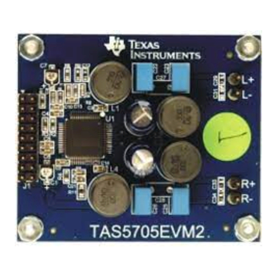
Page 3: Tas5705Evm2 Printed-Circuit Board
Figure 1. TAS5705EVM2 Printed-Circuit Board The TAS5705EVM2, together with other TI components on this board, is a complete 2.1-channel digital audio amplifier system. The MC57XXPSIA Controller board includes a USB interface, a digital input (SPDIF), analog inputs via the ADC (PCM1808), power inputs and other features like a mute function and power down. -
Page 4: Overview
• Double-sided plated-through PCB, 1-oz copper • Access to control signal gain and data format through EVM-software graphic user interface (GUI) TAS5705EVM2 : STEREO DIGITAL INPUT AMPLIFIER WITH EQ and DRC SLOU223A – December 2008 – Revised January 2009 Submit Documentation Feedback... -
Page 5: Installation
2.1.1 Connecting the TAS5705EVM2 to MC57xxPSIA On the right side of the MC57xxPSIA is a terminal block and another on the left of the TAS5705EVM2 (labeled J1). Carefully place the MC57xxPSIA block above the TAS5705EVM2 block and gently push down. -
Page 6: Connecting Tas5705Evm2 To Mc57Xxpsia
2.1.2 PSU Interface The TAS5705EVM2 is powered by two power supplies connected to the MC57xx controller board: a 5-V power supply (VIN) and a 8-V to 24-V (PVDD) power supply. The 3.3-V level is generated on the board by a voltage regulator from the 5-V supply. - Page 7 MC57xxPSIA board facilitates the connection between a host computer and the device. The EVM USB circuit is powered by the 5-V USB line of the host PC and is independent of the power supplies available on the board. The USB device that is used is a TAS1020B from Texas Instruments. 2.1.5...
-
Page 8: Software Installation
The setting here is simply to synchronize the GUI and the device. Figure 5. Graphical User Interface Initial Window TAS5705EVM2 : STEREO DIGITAL INPUT AMPLIFIER WITH EQ and DRC SLOU223A – December 2008 – Revised January 2009... -
Page 9: Using The Evm Software
I2C registers can be written or read using this tool. I2C command file can be sent by selecting the command file and Execute command. SLOU223A – December 2008 – Revised January 2009 TAS5705EVM2 : STEREO DIGITAL INPUT AMPLIFIER WITH EQ and DRC Submit Documentation Feedback... -
Page 10: Volume Function
Figure 7. Volume Control Biquad GUI Using the right button of mouse, select Biquad GUI (Figure Figure 8. Selecting Biquad GUI TAS5705EVM2 : STEREO DIGITAL INPUT AMPLIFIER WITH EQ and DRC SLOU223A – December 2008 – Revised January 2009 Submit Documentation Feedback... -
Page 11: Drc Gui
10). Click on the DRC function, and check to see if DRC is enabled in the property window. Figure 10. DRC Parameters SLOU223A – December 2008 – Revised January 2009 TAS5705EVM2 : STEREO DIGITAL INPUT AMPLIFIER WITH EQ and DRC Submit Documentation Feedback... -
Page 12: Activating The Drc Gui
Figure 12. Time Constants Button Time constants: Select the time constants to adjust the energy, attack, and decay filters (Figure 12). TAS5705EVM2 : STEREO DIGITAL INPUT AMPLIFIER WITH EQ and DRC SLOU223A – December 2008 – Revised January 2009 Submit Documentation Feedback... -
Page 13: Disable Biquads
Figure 13. Disabling the Biquads TAS5705EVM2 Quick-Start Setup Guide This section discusses the five most common configurations of the TAS5705EVM2, and how to enable the headphone mode. For faster setup, you can load the I C initialization script of each configuration from the CD. -
Page 14: Jumpers And Control Utilities On Mc57Xxpsia Board
LED5: SPDIF signal locked LED6: FAULT (Not used with TAS5705EVM2) LED7: PDN switch (S4) is depressed LED8: MUTE switch (S5) is depressed TAS5705EVM2 : STEREO DIGITAL INPUT AMPLIFIER WITH EQ and DRC SLOU223A – December 2008 – Revised January 2009 Submit Documentation Feedback... -
Page 15: Board Layouts, Bill Of Materials, And Schematic
Board Layouts, Bill of Materials, and Schematic TAS5705EVM2 and MC57xxPSIA Board Layouts Figure 14. TAS5705EVM2 Top Assembly Figure 15. MC57xxPSIA Top Assembly SLOU223A – December 2008 – Revised January 2009 TAS5705EVM2 : STEREO DIGITAL INPUT AMPLIFIER WITH EQ and DRC Submit Documentation Feedback... -
Page 16: Bill Of Materials
No Alt. Part Num ALUM-HEX Electronics Hex Nut, 4-40, Zinc/Steel HW1–HW4 Building HNZ440 Digi-Key H216 No Alt. Part Num Fasteners TAS5705EVM2 : STEREO DIGITAL INPUT AMPLIFIER WITH EQ and DRC SLOU223A – December 2008 – Revised January 2009 Submit Documentation Feedback... -
Page 17: Schematic
Schematic The schematic for TAS5705EVM2 and MC57xxPSIA are located at the end of this document. Quick-Start Setup Guide This section discusses the five most common configurations of the TAS5705EVM2, and how to enable the Headphone mode. Common Configurations: Corresponding I C Script 1. -
Page 18: Btl Bd (Default: Bd Mode)
CD or TI Web site).The format for the config file can be .ini or .CFG 3. Connect to the device: Target > Connect. 4. Go to Tools > I C Memory Tools. TAS5705EVM2 : STEREO DIGITAL INPUT AMPLIFIER WITH EQ and DRC SLOU223A – December 2008 – Revised January 2009 Submit Documentation Feedback... - Page 19 6. Finally uncheck the shutdown box to bring the device out of Shutdown mode, and adjust the Master Volume as desired. SLOU223A – December 2008 – Revised January 2009 TAS5705EVM2 : STEREO DIGITAL INPUT AMPLIFIER WITH EQ and DRC Submit Documentation Feedback...
- Page 20 YONG GWAN KIM, SREENATH UNNIKRISHNAN, JOSEY ANGILI Schematic Rev: Schematic Rev: Mod: Mod: PCB Rev: PCB Rev: Sheet Sheet Save Date: Save Date: JULY 25, 2008 Print Date Print Date Fri Jul 25, 2008 Filename: Filename: TAS5705EVM2.SCH Drawn By: Drawn By:...
- Page 21 USB INTERFACE ENGINEERING EVALUATION ONLY USB BOOT EPROM TO EVM BOARD (A0 IN DEFAULT) TAS1020BPFB USB I/O USB RESET DECOUPLING EVM CONTROLLER BOARD PROJECT: PROJECT: YONG GWAN KIM Design Team: Design Team: Schematic Rev: Schematic Rev: Mod: Mod: PCB Rev: PCB Rev: Sheet Sheet...
- Page 22 SPDIF RECEIVER ENGINEERING EVALUATION ONLY SPDIF SPDIF INPUT LOCK DATA FORMAT FMT1 FMT0 24Bit/MSB/I2S RCA INPUT (LOW) SPDIF INPUT SELECT 1-2: OPTO INPUT DIR9001PW 2-3: RCA INPUT OPTO INPUT JP1 IN: SCKO = 512 Fs (HIGH) JP1 OUT: SCKO = 256 Fs (DEFAULT) EVM BOARD MASTER RESET...
- Page 23 ADC / CONNECTOR I/O ENGINEERING EVALUATION ONLY TO EVM BOARDS FAULT NOTES ON JUMPERS IN: LIN/RIN = 1Vrms MAX. OUT: LIN/RIN = 2Vrms MAX. ANALOG INPUTS MUTE (SDIN1) (SDIN2) PCM1808PW FROM SPDIF MC012 PSIA (1-2) (2-3) FROM USB FROM MASETER RESET FROM VR1 HIGH POWER INPUT 3.3V DECOUPLING...
-
Page 24: Appendix A 2 X Btl Bd (Default: Bd Mode)
Appendix A www.ti.com Appendix A 2 X BTL BD (Default: BD mode) Following initial scripts may also be found on the installation CD or TI Web site. The following scripts use .ini format where the first column is type of write command ("01" means single byte, "02" means multi-byte, "00"... -
Page 25: Appendix B 2 X Btl Ad (Default: Ad Mode)
Appendix B www.ti.com Appendix B 2 X BTL AD (Default: AD mode) Following initial scripts may also be found on the installation CD or TI Web site. The following scripts use .ini format where the first column is type of write command ("01" means single byte, "02" means multi-byte, "00"... -
Page 26: Appendix Cbd 2.1 Using External Sub
Appendix C www.ti.com Appendix C BD 2.1 Using External SUB Following initial scripts may also be found on the installation CD or TI Web site. The following scripts use .ini format where the first column is type of write command ("01" means single byte, "02" means multi-byte, "00"... -
Page 27: Appendix Dad 2.1 Using External Sub
Appendix D www.ti.com Appendix D AD 2.1 Using External SUB Following initial scripts may also be found on the installation CD or TI Web site. The following scripts use .ini format where the first column is type of write command ("01" means single byte, "02" means multi-byte, "00"... - Page 28 EVALUATION BOARD/KIT IMPORTANT NOTICE Texas Instruments (TI) provides the enclosed product(s) under the following conditions: This evaluation board/kit is intended for use for ENGINEERING DEVELOPMENT, DEMONSTRATION, OR EVALUATION PURPOSES ONLY and is not considered by TI to be a finished end-product fit for general consumer use. Persons handling the product(s) must have electronics training and observe good engineering practice standards.
- Page 29 IMPORTANT NOTICE Texas Instruments Incorporated and its subsidiaries (TI) reserve the right to make corrections, modifications, enhancements, improvements, and other changes to its products and services at any time and to discontinue any product or service without notice. Customers should obtain the latest relevant information before placing orders and should verify that such information is current and complete.
- Page 30 Mouser Electronics Authorized Distributor Click to View Pricing, Inventory, Delivery & Lifecycle Information: Texas Instruments TAS5705EVM2...
Need help?
Do you have a question about the TAS5705EVM2 and is the answer not in the manual?
Questions and answers