Table of Contents
Advertisement
SERVICE MANUAL
Main Section
I Specifications
I Preparation for Servicing
I Adjustment Procedures
I Schematic Diagrams
I CBA's
I Exploded Views
I Parts List
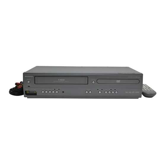
VIDEO CASSETTE RECORDER
STANDBY-ON
POWER ON
VIDEO
AUDIO
DVD PLAYER &
MWD2206A
REC
TIMER REC
REW
F.FWD STOP/EJECT
PLAY
RECORD
IR
When servicing the deck
mechanism, refer to MK14 Deck
Mechanism Section.
Deck Mechanism Part No.:
N2440FL
OPEN/CLOSE
VCR
DVD
DISC IN
PLAY
CHANNEL
SOURCE
PREV
STOP
PLAY
NEXT
Advertisement
Table of Contents

Subscribe to Our Youtube Channel
Related Manuals for Magnavox MWD2206A


Summary of Contents for Magnavox MWD2206A
- Page 1 Mechanism Section. I Adjustment Procedures I Schematic Diagrams Deck Mechanism Part No.: I CBA’s I Exploded Views N2440FL I Parts List DVD PLAYER & VIDEO CASSETTE RECORDER MWD2206A STANDBY-ON OPEN/CLOSE POWER ON TIMER REC DISC IN PLAY F.FWD STOP/EJECT PLAY RECORD...
- Page 2 IMPORTANT SAFETY NOTICE Proper service and repair is important to the safe, reliable operation of all Funai Equipment. The service procedures recommended by Funai and described in this service manual are effective methods of performing service operations. Some of these service special tools should be used when and as recommended.
-
Page 3: Table Of Contents
MAIN SECTION DVD PLAYER & VIDEO CASSETTE RECORDER MWD2206A Main Section I Specifications I Preparation for Servicing I Adjustment Procedures I Schematic Diagrams I CBA’s I Exploded Views I Parts List TABLE OF CONTENTS Specifications ................1-1-1 Laser Beam Safety Precautions . -
Page 4: Specifications
SPECIFICATIONS < VCR Section > Description Unit Minimum Nominal Maximum Remark 1. Video 1-1. Video Output (PB) Vp-p SP Mode 1-2. Video Output (R/P) Vp-p SP Mode, 1-3. Video S/N Y (R/P) W/O Burst 1-4. Video Color S/N AM (R/P) SP Mode 1-5. - Page 5 < DVD Section > Item Conditions Unit Nominal Limit 75 Ω load 1. Video Output ± 0.1 75 Ω load 2. Coaxial Digital Out mVpp ± 50 3. Audio (PCM) 1 kHz, 0 dB, 47k Ω load 3-1. Output Level Vrms 47k Ω...
-
Page 6: Laser Beam Safety Precautions
LASER BEAM SAFETY PRECAUTIONS This DVD player uses a pickup that emits a laser beam. Do not look directly at the laser beam coming from the pickup or allow it to strike against your skin. The laser beam is emitted from the location shown in the figure. When checking the laser diode, be sure to keep your eyes at least 30 cm away from the pickup lens when the diode is turned on. -
Page 7: Important Safety Precautions
IMPORTANT SAFETY PRECAUTIONS Product Safety Notice Also check areas surrounding repaired locations. J. Be careful that foreign objects (screws, solder Some electrical and mechanical parts have special droplets, etc.) do not remain inside the set. safety-related characteristics which are often not K. - Page 8 Safety Check after Servicing Examine the area surrounding the repaired location for damage or deterioration. Observe that screws, parts, and wires have been returned to their original positions. Afterwards, do the following tests and confirm the specified values to verify compliance with safety standards. 1.
-
Page 9: Standard Notes For Servicing
STANDARD NOTES FOR SERVICING Circuit Board Indications Pb (Lead) Free Solder 1. The output pin of the 3 pin Regulator ICs is When soldering, be sure to use the Pb free solder. indicated as shown. How to Remove / Install Flat Pack-IC Top View Bottom View 1. - Page 10 3. The flat pack-IC on the CBA is affixed with glue, so With Soldering Iron: be careful not to break or damage the foil of each 1. Using desoldering braid, remove the solder from pin or the solder lands under the IC when all pins of the flat pack-IC.
- Page 11 2. Installation With Iron Wire: 1. Using desoldering braid, remove the solder from 1. Using desoldering braid, remove the solder from all pins of the flat pack-IC. When you use solder the foil of each pin of the flat pack-IC on the CBA flux which is applied to all pins of the flat pack-IC, so you can install a replacement flat pack-IC more you can remove it easily.
- Page 12 Instructions for Handling Semi- conductors Electrostatic breakdown of the semi-conductors may occur due to a potential difference caused by electrostatic charge during unpacking or repair work. 1. Ground for Human Body Be sure to wear a grounding band (1 MΩ) that is properly grounded to remove any static electricity that may be charged on the body.
-
Page 13: Preparation For Servicing
PREPARATION FOR SERVICING How to Enter the Service Mode About Optical Sensors Caution: An optical sensor system is used for the Tape Start and End Sensors on this equipment. Carefully read and follow the instructions below. Otherwise the unit may operate erratically. What to do for preparation Insert a tape into the Deck Mechanism Assembly and press the [PLAY] button. -
Page 14: Cabinet Disassembly Instructions
CABINET DISASSEMBLY INSTRUCTIONS 1. Disassembly Flowchart Removal This flowchart indicates the disassembly steps to gain Remove/*Unhook/ Loc. Part Fig. Unlock/Release/ Note access to item(s) to be serviced. When reassembling, Unplug/Desolder follow the steps in reverse order. Bend, route, and dress the cables as they were originally. DVD Open/ [10] D6 Desolder... - Page 15 4. When reassembling, solder wire jumpers as shown in Fig. D6. 5. Before installing the Deck Assembly, be sure to CN401 (S-3) CN601 place the pin of LD-SW on Main CBA as shown in Fig. D6. Then, install the Deck Assembly while (S-3) aligning the hole of Cam Gear with the pin of LD- [4] DVD...
- Page 16 (S-7) (S-7) (S-8) (S-7) (S-8) [8] VCR Chassis Unit Fig. D5 1-6-3 H986NDC...
- Page 17 Cylinder Assembly FE Head ACE Head Assembly SW512 Lead with blue stripe [9] Deck Assembly LD-SW Desolder (S-11) [12] Main CBA [9] Deck Assembly [11] Power SW CBA Cam Gear (S-9) Hole [12] Main CBA [10] DVD Shaft (S-10) Open/Close CBA Hole Desolder LD-SW...
- Page 18 3. HOW TO EJECT MANUALLY 1. Remove the Top Case, Front Assembly and Top Bracket. 2. Remove four Screws (S-3) in Fig. D3. Do not disconnect connectors. 3. While lifting up the DVD Mechanism, rotate the roulette in the direction of the arrow as shown below. 4.
-
Page 19: Electrical Adjustment Instructions
ELECTRICAL ADJUSTMENT INSTRUCTIONS General Note: “CBA” is abbreviation for Head Switching Position “Circuit Board Assembly.” Adjustment NOTE: Purpose: To determine the Head Switching position 1. Electrical adjustments are required after replacing during playback. circuit components and certain mechanical parts. Symptom of Misadjustment: May cause Head It is important to do these adjustments only after Switching noise or vertical jitter in the picture. -
Page 20: How To Initialize The Dvd Player & Vcr
HOW TO INITIALIZE THE DVD PLAYER & VCR To put the program back at the factory-default, initialize the DVD player & VCR as the following procedure. < DVD Section > 1. Press [DVD], [1], [2], [3], [4], and [DISPLAY] buttons on the remote control unit in that order. Fig. -
Page 21: Firmware Renewal Mode
FIRMWARE RENEWAL MODE 1. Turn the power on and remove the disc on the tray. " ******* " differ depending on the models. 2. To put the DVD player into version up mode, press [DVD], [9], [8], [7], [6], and [SEARCH MODE] F/W Version Up Mode Model No : ******* buttons on the remote control unit in that order. -
Page 22: Function Indicator Symbols
FUNCTION INDICATOR SYMBOLS Note: If a mechanical malfunction occurs, the power is turned off. When the power comes on again after that by pressing [STANDBY-ON] button, an error message is displayed on the TV screen for 5 seconds. Cause Indicator Active When reel or capstan mechanism is not “EJECT A R”... -
Page 23: Block Diagrams
BLOCK DIAGRAMS <VCR SECTION> Servo / System Control Block Diagram 1-11-1 H986NBLS... - Page 24 Video Block Diagram 1-11-2 H986NBLV...
- Page 25 Audio Block Diagram 1-11-3 H986NBLA...
- Page 26 Power Supply Block Diagram 1-11-4 H986NBLP...
- Page 27 BLOCK DIAGRAMS <DVD SECTION> DVD System Control / Servo Block Diagram 1-11-5 H986NBLSD...
- Page 28 Digital Signal Process Block Diagram 1-11-6 H986NBLD...
- Page 29 DVD Video / Audio Block Diagram 1-11-7 H986NBLVD...
-
Page 30: Schematic Diagrams / Cba's And Test Points
SCHEMATIC DIAGRAMS / CBA’S AND TEST POINTS Standard Notes WARNING Many electrical and mechanical parts in this chassis have special characteristics. These characteristics often pass unnoticed and the protection afforded by them cannot necessarily be obtained by using replacement components rated for higher voltage, wattage, etc. - Page 31 LIST OF CAUTION, NOTES, AND SYMBOLS USED IN THE SCHEMATIC DIAGRAMS ON THE FOLLOWING PAGES: 1. CAUTION: FOR CONTINUED PROTECTION AGAINST FIRE HAZARD, REPLACE ONLY WITH THE SAME TYPE FUSE. ATTENTION: POUR UNE PROTECTION CONTINUE LES RISQES D'INCELE N'UTILISER QUE DES FUSIBLE DE MÊME TYPE. RISK OF FIRE-REPLACE FUSE AS MARKED.
- Page 32 Main 1/7 Schematic Diagram < VCR Section > H986NSCM1 1-12-3...
- Page 33 Main 2/7 , Sensor & Power SW Schematic Diagram < VCR Section > H986NSCM2 1-12-4...
- Page 34 Main 3/7 Schematic Diagram < VCR Section > H986NSCM3 1-12-5...
- Page 35 Main 4/7 Schematic Diagram < VCR Section > H986NSCM4 1-12-6...
- Page 36 Main 5/7 Schematic Diagram < VCR Section > 1-12-7 H986NSCM5...
- Page 37 Main 6/7 & DVD Open/Close Schematic Diagram < VCR Section > H986NSCM6 1-12-8...
- Page 38 Main 7/7 Schematic Diagram < VCR Section > NOTE: CAUTION ! CAUTION ! The voltage for parts in hot circuit is measured using Fixed voltage (or Auto voltage selectable) power supply circuit is used in this unit. For continued protection against fire hazard, hot GND as a common terminal.
- Page 39 DVD Main 1/3 Schematic Diagram < DVD Section > 1 NOTE: Either IC461 or IC462 is used for DVD MAIN CBA UNIT. 1-12-10 H986NSCD1...
- Page 40 DVD Main 2/3 Schematic Diagram < DVD Section > H986NSCD2 1-12-11...
- Page 41 IC101 Voltage Chart ~ : Voltage is not consistent ----- : Not used Unit : Volts PIN.NO PLAY STOP PIN.NO PLAY STOP PIN.NO PLAY STOP PIN.NO PLAY STOP PIN.NO PLAY STOP PIN.NO PLAY STOP PIN.NO PLAY STOP PIN.NO PLAY STOP ----- ----- -----...
- Page 42 DVD Main 3/3 Schematic Diagram < DVD Section > H986NSCD3 1-12-13...
- Page 43 Main CBA Top View CAUTION ! Because a hot chassis ground is present in the power CAUTION ! supply circut, an isolation transformer must be used. Fixed voltage (or Auto voltage selectable) power supply circuit is used in this unit. For continued protection against fire hazard, If Main Fuse (F1001) is blown , check to see that all components in the power supply Also, in order to have the ability to increase the input...
- Page 44 Main CBA Bottom View CAUTION ! Because a hot chassis ground is present in the power CAUTION ! supply circut, an isolation transformer must be used. Fixed voltage (or Auto voltage selectable) power supply circuit is used in this unit. For continued protection against fire hazard, Also, in order to have the ability to increase the input If Main Fuse (F1001) is blown , check to see that all components in the power supply...
-
Page 45: Waveforms
WAVEFORMS NOTE: Input VCR: COLOR BAR SIGNAL (WITH 1KHz AUDIO SIGNAL) (WF1~WF3, WF10~WF13, WF15) DVD: POWER ON (STOP) MODE (WF4~WF6) CD: 1kHz PLAY (WF7~WF9) TP751 Pin 8 of CN1601 Pin 13 of CN1601 V-OUT E-E V-OUT E-E 0.2V 0.2V 20µs AUDIO-L AUDIO-L 0.5ms... - Page 46 NOTE: Input VCR: COLOR BAR SIGNAL (WITH 1KHz AUDIO SIGNAL) (WF1~WF3, WF10~WF15) DVD: POWER ON (STOP) MODE (WF4~WF6) CD: 1kHz PLAY (WF7~WF9) WF10 WF13 Pin 2 of TU701 Pin 12 of TU701 MOD-A 0.5V 0.2ms PLL-DATA WF11 WF14 Pin 6 of TU701 Pin 14 of TU701 MOD-V 0.5V...
-
Page 47: Wiring Diagram < Vcr Section
WIRING DIAGRAM < VCR SECTION > 1-14-1 H986NWI... -
Page 48: Wiring Diagram < Dvd Section
WIRING DIAGRAM < DVD SECTION > H986NWID 1-14-2... -
Page 49: System Control Timing Charts
SYSTEM CONTROL TIMING CHARTS < VCR Section > Mode SW: LD-SW LD-SW Position detection A/D Input voltage Limit Symbol (Calculated voltage) 3.76 V ~ 4.50 V (4.12 V) 4.51 V ~ 5.00 V (5.00 V) 0.00 V ~ 0.25 V (0.00 V) 1.06 V ~ 1.50 V (1.21 V) 0.66 V ~ 1.05 V (0.91 V) 1.99 V ~ 2.60 V (2.17 V) - Page 50 Still/Slow Control Frame Advance Timing Chart 1) SP Mode 18 RF-SW The first rise of RF-SW after a rise in F-AD signal F-AD (Internal Signal) "H" "H" "Z" C-DRIVE "L" "L" Stop detection (T2) Acceleration Detection (T1) Slow Tracking Value PB CTL Reversal Limit Value 20ms...
- Page 51 2) LP/SLP Mode 18 RF-SW The first rise of RF-SW after a rise in F-AD signal F-AD (Internal Signal) "H" "H" "Z" C-DRIVE "L" "L" Stop detection (T2) Acceleration Detection (T1) Slow Tracking Value PB CTL Reversal Limit Value 20ms 27 C-F/R 79 H-A-SW 78 C-ROTA...
- Page 52 EJECT ST-S/ END-S "OFF" CASS.LOAD LD-FWD 0.2S LD-REV 0.7S LD-FWD 0.4S LD-FWD 0.2S LD-REV 0.2S LD-FWD 0.5S LD-REV STOP(A) PLAY LD-FWD PLAY LD-FWD LD-REV 0.2S LD-FWD PLAY PLAY PAUSE (SLOW) LD-FWD STILL(SLOW) PLAY LD-REV 0.2S LD-FWD PLAY STOP /EJECT LD-REV STOP(A) Fig.
- Page 53 STOP(A) STOP LD-REV 0.2S LD-FWD STOP /EJECT 1.0S LD-FWD 0.5S LD-REV STOP(A) LD-REV 0.2S LD-FWD STOP /EJECT LD-REV 1.0S LD-FWD 0.5S LD-REV STOP(A) LD-FWD PAUSE LD-FWD 2.5S Short REV LD-REV 0.2S LD-FWD REC PAUSE REC or PAUSE STOP /EJECT LD-FWD 1.5S LD-REV 0.2S...
- Page 54 < DVD Section > Tray Close ~ Play / Play ~ Tray Open Tray Disc Disc Tray Play Close Rotation Stop Open 3.3V Tray IN (TL221) 1.65V Sled Drive (TP303) 1.65V Disc Drive (TP301) 1.65V Focus Drive (TP304) Tracking Drive 1.65V (TP302) 1-15-6...
-
Page 55: Ic Pin Function Descriptions
IC PIN FUNCTION DESCRIPTIONS < VCR Section > Signal Active Mark Function Name Level IC501 (SERVO/SYSTEM CONTROL/OSD) Loading Motor LM-FWD/ “H” ≥ 4.5 V, “L” ≤ 1.0 V FWD/ REV H/Z/L Output Signal Active Power On Mark Function OUT P-ON-L Name Level Signal to Low... - Page 56 Signal Active Signal Active Mark Function Mark Function Name Level Name Level VDD2 VDD2 Video Head Switching Low Path Filter Pulse Signal IN AFCC Input Signal DELAY Adjusted For AFC Voltage Low Path Filter A/D Key Data OUT AFCLPF Output Signal IN KEY-2 Signal 2 For AFC...
-
Page 57: Lead Identifications
LEAD IDENTIFICATIONS KRA103M-AT/P 2SC1815-GR(TE2 F T) RC4580IP KRC103M-AT/P KTC3198-Y-AT/P KTA-1266-GR-AT/P KTC3203-Y-AT/P KTA1267-Y-AT/P KTC3193-Y-AT/P KTC3199-(BL,Y)-AT/P E C B E C B MM1637XVBE EL817A PQ1LAX95MSPQ TC4053BF(EL N F) RN1511(TE85R.F) 1: VREF 2: GND 3: VC 4: VIN 5: VOUT B1 E B2 LA71205M-MPB-E MN101D08DEK PT204-6B-12... -
Page 58: Exploded Views
EXPLODED VIEWS Cabinet 2L071 2L071 2L071 2L021 2L021 2L071 2L021 L0-9 2L082 L0-9 W006 2L021 2L062 Sensor CBA 2L051 DVD Main 2B11 CBA Unit Main CBA 2L012 Power SW CBA Sensor CBA W012 2B16 These FFC cables are included in 1B2 (DVD mechanism). 2B15 2L051 2B13... - Page 59 Packing Unit 1-18-2 H9801PEX...
-
Page 60: Mechanical Parts List
MECHANICAL PARTS LIST PRODUCT SAFETY NOTE: Products marked with a # have special characteristics important to safety. Before replacing any of these components, read carefully the product safety notice in this service manual. Don't degrade the safety of the product through improper servicing. -
Page 61: Electrical Parts List
ELECTRICAL PARTS LIST PRODUCT SAFETY NOTE: Products marked with a Ref. No. Description Part No. # have special characteristics important to safety. C315 CHIP CERAMIC CAP . B K 0.1µF/25V CHD1EKB0B104 Before replacing any of these components, read C316 CHIP CERAMIC CAP . F Z 1µF/10V CHD1AZB0F105 carefully the product safety notice in this service C317... - Page 62 Ref. No. Description Part No. Ref. No. Description Part No. C536 CHIP CERAMIC CAP . B K 1000pF/50V CHD1JKB0B102 C1395 ELECTROLYTIC CAP . 470µF/6.3V M CE0KMASDL471 C537 CHIP CERAMIC CAP . B K 1000pF/50V CHD1JKB0B102 C1421 CHIP CERAMIC CAP . B K 0.01µF/50V CHD1JKB0B103 C540 CHIP CERAMIC CAP .
- Page 63 Ref. No. Description Part No. Ref. No. Description Part No. IC501 SYSCON IC MN101D08DEK QSZAA0RMS034 Q1204 TRANSISTOR KTA-1266-GR-AT/P NQS4KTA1266P IC751 IC SWITCH TC4053BF(EL N F) QSZBA0TTS163 Q1351 TRANSISTOR KTC3199-Y-AT/P NQSYKTC3199P IC1001# PHOTOCOUPLER EL817A NPEA000EL817 Q1385 TRANSISTOR KTC3199-Y-AT/P NQSYKTC3199P IC1002 VOLTAGE REGULATOR PQ1LAX95MSPQ QSZBA0TSH053 Q2002 TRANSISTOR KTC3199-Y-AT/P...
- Page 64 Ref. No. Description Part No. Ref. No. Description Part No. CHIP RES. 1/10W J 330k Ω CHIP RES. 1/10W J 10k Ω R411 RRXAJB5Z0334 R612 RRXAJB5Z0103 CHIP RES. 1/10W J 120 Ω CHIP RES. 1/10W J 10k Ω R412 RRXAJB5Z0121 R616 RRXAJB5Z0103 CHIP RES.
- Page 65 Ref. No. Description Part No. Ref. No. Description Part No. CHIP RES. 1/10W J 100k Ω R1240 RRXAJB5Z0104 JC01 CHIP CERAMIC CAP . CH J 100pF/50V CHD1JJBCH101 CARBON RES. 1/6W J 10 Ω CHIP RES.(1608) 1/10W 0 Ω R1245 RCX6JATZ0100 JC05 RRXAZB5Z0000 CHIP RES.
- Page 66 MWD2206A H986NUD 2006-04-03...
Need help?
Do you have a question about the MWD2206A and is the answer not in the manual?
Questions and answers