Advertisement
Available languages
Available languages
Quick Links
EAntenna's multi-band OWA antennas also represent the biggest development in HF to 70MHz single-band antennas, but optimizing the
results in the same boom several bands.
This performance is characterized by:
The feed is direct to 50 Ohms with a single coax.
The bandwidth of the OWA is the best development of technology to cover the entire bandwidth and have a low SWR.
The radiation lobe is similar to LFA, but has more front gain than LFA.
The F/B ratio is medium to high, compensating for the high frontal gain.
All of this is explained, because in EAntenna: Millimeter by millimeter, we manufacture and build with CNC machinery and/or prepared for
measurements with centimeters, for an exact measurement. Every piece of aluminum is taken care of, filing it of external and internal
surfaces. All this is done by hand, by qualified people prepared for a final product of extreme quality.
All the hardware is stainless Steel W4.
The aluminium used is T5 6061/6063 and T6 6082; the best alloys for manufacturing antennas with extreme weather resistance.
was double here
EAntenna's OWA antennas are always insulated from the boom, with German PP (Polypropylene, -30ºC/+60ºC) plastic clamps.
Specifications of the 5070OWA8:
Square boom size is 30x30x2mm.
The elements are with 13mm diameter, splitted in 2 parts to get along with a suitable transport length.Mast to plate is an 100x100mm with
6mm thickness and M6 square U-bolts for the boom to the plate and M8 U-bolts for the plate to the mast.
Characteristics of the 5070OWA8
If you can't put 2 antennas on your tower, don't worry, this is your solution to take advantage of the propagation ES seasons on these 2 bands,
You don't need 2 coax cables, this antenna have only 1 coax to the Radio.
Even when you go to the field or portable, with a simple TV rotor you can move without problems.
Simple and fast assembly, because the pieces of the boom connection are very easy to assemble.
Very solid antenna construction, and with an acceptable weight.
Peso: 4,2 Kg.
Max. Potencia: 5,0 kW
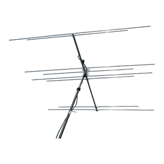
Yagi Antenna
Yagi Antenna
5070OWA8
5070OWA8
2,15m
Artikel nr: 17810.64-8
Rev. V1.6 - 22/02/2021
Weather
Advertisement

Related Manuals for EAntenna 5070OWA8


Summary of Contents for EAntenna 5070OWA8
- Page 1 The F/B ratio is medium to high, compensating for the high frontal gain. All of this is explained, because in EAntenna: Millimeter by millimeter, we manufacture and build with CNC machinery and/or prepared for measurements with centimeters, for an exact measurement. Every piece of aluminum is taken care of, filing it of external and internal surfaces.
-
Page 2: Specifications
SPECIFICATIONS EAntenna 5070OWA8 Elements: 70~70,5 MHz. Frequency Range: 50~52 MHz. 14,0..21,0 MHz. Gain: 8,6 dBi 8,58 dBi 18,76 dB F/B: 20,43 dB 3500 KHz. 3800 KHz. SWR: 1,0:1~1,4:1 1,0:1~1,3:1 Ω 50 Ohms Impedance 50 Ohms Max. Power: 10 kW. 10 kW. - Page 3 REFLECTOR 6 2,916m REFLECTOR 4 0,044m 2,104m COAX ELEMENT DRIVEN 6 2,900m 0,836m DRIVEN 4 0,935m 2,054m DIRECTOR 6-1 1,060m 2,770m 2,13m DIRECTOR 4-1 1,129m 2,028m PLACA/ PLATE 1,200m DIRECTOR 4-2 2,000m 1,981m DIRECTOR 6-2 2,660m 2,080m...
- Page 4 ESPAÑOL Para montar el BOOM, tiene que hacer coincidir frontalmente las partes de boom que tienen la misma letra ( p.ej: A-A, B-B, C-C etc), y una vez hecho, las placas (EA010039) se van fijando con los tornillos DIN 933 M6X16 y arandela DIN 9021 M6. Se recomienda poner todas los tornillos y arandelas antes de fijarla a tope para no dañar ninguna rosca del BOOM.
- Page 5 ESPAÑOL El primer paso de ensamblaje de los elementos es colocar en orden por diámetros según la pagina 2. Una vez hecho esto tener en cuenta que en cada extremo de los elementos hay una parte de cada tubo que tiene los agujeros mar gruesos. Estos son los que van en el extremo hacia el extremo de la antena, ya que los agujeros anchos son donde entra la cabeza del tornillo DIN 7984 y presiona al tubo interior.
- Page 6 ENGLISH The first step of assembling the elements is to place in order by diameters according to page 2. Once this is done keep in mind that at each end of the elements there is a part of each tube that has thick sea holes. These are the ones that go at the end towards the end of the antenna, since the wide holes are where the head of the DIN 7984 screw enters.
- Page 7 PLACAS SUJECIÓN MÁSTIL ESPAÑOL La placa de sujeción BOOM/MÁSTIL (EA013018) de 200X100X6mm consta de 8 agujeros; 4 gruesos para los abarcones redondos y 4 para los abarcones cuadrados que sujetan el BOOM. Los 4 agujeros de mayor grosor tienen la función de que hagan la mayor fuerza sobre el mástil, mediante abarcones redondos de M8. Los abarcones redondos de M8 (A-0163), van fijados mediante arandela DIN 9021 M8 y tuerca DIN 934 M8 proporcionadas en el mismo abarcón, y fijada al mástil con la Mordaza (23035.50).
- Page 8 MAST TO BOOM PLATE ASSEMBLY ENGLISH The clamping plate BOOM / MAST (EA013018) 200X100X6mm consists of 8 holes; 4 thick for round U-bolts and 4 square U-bolts for securing the BOOM. The 4 holes are thicker function that make the greatest force on the mast by means of M8 round U-bolts. Round U-bolts M8 (A-0163), are secured by washer DIN 9021 M8 and nut DIN 934 M8 provided in the same U-bolt, and fixed to the mast with clamp (23035.50).
- Page 9 ESPAÑOL Alimentación: Cuando el montaje está totalmente terminado, lo último es alimentar la antena con el cable coaxial. Siga los dibujos de como va la alimentación. Simplemente, abrir el coaxial y soldar los 2 terminales suministrados, después colocando estos en los tonillos del elemento de alimentación (DRV.6) y fijandolo con las tuercas y arandelas. La posición de los terminales es indiferente.
- Page 10 ENGLISH Feeding: When the installation is fully completed, the last step is feed the antenna with coaxial cable. Follow the drawings. Simply, cut and open the 2 coax and solder terminals supplied after placing these in the Driven element (DRV.6) and fixing it with nuts and washers.
- Page 11 PACKING LIST BOLSA 1 - BAG #1 LISTA DE PIEZAS PART # DESCRIPCION MEDIDAS CANTIDAD IMAGEN PIEZA Nº DESCRIPTION SIZES QUANTITY PART IMAGE Placa Mástil/Boom 100 x 100 x 6mm EA013018 Mast and Boom plate Abarcon A-0163 50mm, M8 U-Bolt. Mordaza 23035.50 50mm...
- Page 12 BOLSA 3 - BAG #3 PART # DESCRIPCION MEDIDAS CANTIDAD IMAGEN PIEZA Nº DESCRIPTION SIZES QUANTITY PART IMAGE Placa para Elementos 150x50x4mm EA010024 Elements plates Placa para Elementos 150x50x4mm EA010026 Elements plates Placa para Elementos 150x100x4mm EA010025 Elements plates 13mm Ø Plásticos 13mm Ø...
- Page 13 PACKING LIST LISTA DE PIEZAS PART # DESCRIPCION MEDIDAS CANTIDAD IMAGEN PIEZA Nº DESCRIPTION SIZES QUANTITY PART IMAGE BOOM A 1395mm x 30mm 50OWA8 BOOM B 740,5mm x 30mm 50OWA8 Punta final de ajuste 100mm x 10mm Adjustmen tips elements REFLECTOR 6m 1458mm x 13mm REFLECTOR 4m...
Need help?
Do you have a question about the 5070OWA8 and is the answer not in the manual?
Questions and answers