Advertisement
Available languages
Available languages
Quick Links
Thank you for choosing EAntenna.
All our products are manufactured and developed with the best materials on the market, to offer the best qualities and guarantees to our
customers.
The LFA antennas have an input impedance of 50 Ohm in the antenna, so no coupling is necessary. The loop is at the same time a coupling
system and director element and this presents many advantages when modeling.
The 'real' impedance of each LFA varies greatly. But, the impedance presented at the antenna entry point is always 50 Ohm. Therefore, there
is no limitation on the results of any optimization tool achieved with a single input impedance, but it manages to change the width and length of
the loop keeping the impedance at 50 Ohm. This feature is very important to ensure good performance, bandwidth and low SWR in the
antenna.
This additional flexibility also allows more lateral lobes to be suppressed and a better front-to-back (F / B) ratio compared to traditional Yagis.
With time it is possible to achieve an excellent balance between design, F/B, gain and bandwidth.
Additionally, the proximity of the loop and the antenna entry point make the LFA less susceptible to noise and static nearby. In addition, the low
level of the LFA lateral lobes provides a winning formula for an antenna with super low noise!
We detail the materials used, for their best use and assembly. All the fittings are made of stainless steel and the aluminum is made of T6061 or
T6063 alloy, known as Duralumin that offers the best conditions to be weatherproof, the force of the wind and the best conductivity. The
plastics used, are Polyamide and offer the best hardness and durability for years and years.
We offer warranty on operation, and warranty on hardware, delivering the hardware kit with some additional pieces for possible losses or
forced breaks. In addition, we offer Allen keys and fixed mounting elements.
In the following pages you can see detailed graphics of the parts.
Peso: 30 Kg.
Max. Potencia: 10 kW
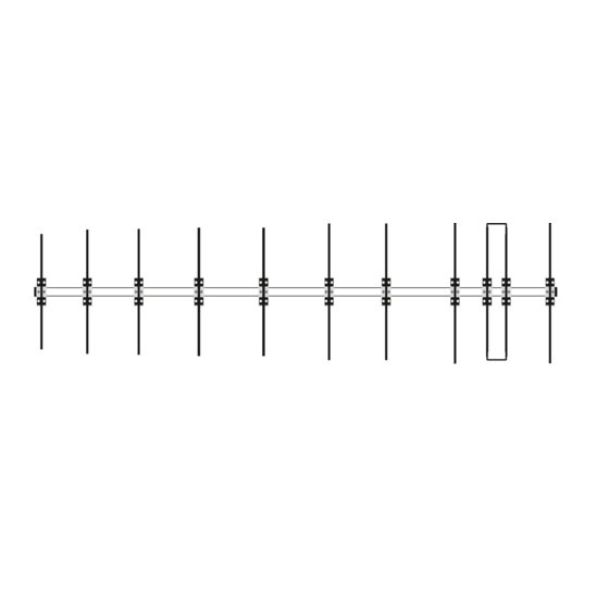
Yagi Antenna
Yagi Antenna
50LFA10
50LFA10
17,75m
17800.06-10
Rev. V1.4 - 20/11/2020
Advertisement

Related Manuals for EAntenna 50LFA10


Summary of Contents for EAntenna 50LFA10
- Page 1 50LFA10 50LFA10 17800.06-10 Thank you for choosing EAntenna. All our products are manufactured and developed with the best materials on the market, to offer the best qualities and guarantees to our customers. The LFA antennas have an input impedance of 50 Ohm in the antenna, so no coupling is necessary. The loop is at the same time a coupling system and director element and this presents many advantages when modeling.
- Page 2 Not to Scale Medidas no a escala 1,2m 0,907m SUJECCIÓN 0,424m 2000mm GUY HOLE ALIMENTACION (2400mm) FEEDPOINT 0,424m 0,564m 2450mm 2000mm 0,988m (2400mm) SUJECCIÓN +/- 0,605m 0,789m GUY HOLE 1,777m 0,811m 4290mm 1,696m 2000mm (2400mm) 3,473m 0,7725m 2,029m 2000mm 5,502m Placa Mástil Mast Plate +/- 8270mm...
- Page 3 ESPAÑOL Para montar el BOOM, tiene que hacer coincidir telescopicamente las partes de boom que tienen la misma letra ( p.ej: A-A, B-B, C-C etc), y una vez hecho, se van fijando con los tornillos DIN 933 M6X16 y arandela DIN 9021 M6. Se recomienda poner todas los torni- llos y arandelas antes de fijarla a tope para no dañar ninguna rosca del BOOM.
- Page 4 ESPAÑOL El primer paso de ensamblaje de los elementos es colocar en orden por diámetros según la pagina 2. Una vez hecho esto tener en cuenta que en cada extremo de los elementos hay una parte de cada tubo que tiene los agujeros mar gruesos. Estos son los que van en el extremo hacia el extremo de la antena, ya que los agujeros anchos son donde entra la cabeza del tornillo DIN 7984 y presiona al tubo interior.
- Page 5 ENGLISH The first step of assembling the elements is to place in order by diameters according to page 2. Once this is done keep in mind that at each end of the elements there is a part of each tube that has thick sea holes. These are the ones that go at the end towards the end of the antenna, since the wide holes are where the head of the DIN 7984 screw enters.
- Page 6 PLACAS SUJECIÓN MÁSTIL ESPAÑOL La placa de sujeción BOOM/MÁSTIL (E A010010 ) de 250X200X10mm consta de 12 agujeros; 4 gruesos para los abarcones redondos y 8 para la pletina (EA010276) que sujetan el BOOM. Los 4 agujeros de mayor grosor tienen la función de que hagan la mayor fuerza sobre el mástil, mediante abarcones redondos de M8. Los abarcones redondos de M8 (A-0163), van fijados mediante arandela DIN 9021 M8 y tuerca DIN 934 M8 proporcionadas en el mismo abarcón, y fijada al mástil con la Mordaza (23035.50).
- Page 7 MAST TO BOOM PLATE ASSEMBLY ENGLISH The clamping plate BOOM / MAST (EA010010) 250X200X10mm consists of 12 holes; 4 thick for round U-bolts and 8 small holes to joint the (EA010276) securing the BOOM. The 4 holes are thicker function that make the greatest force on the mast by means of M8 round U-bolts. Round U-bolts M8 (A-0163), are secured by washer DIN 9021 M8 and nut DIN 934 M8 provided in the same U-bolt, and fixed to the mast with clamp (23035.50).
- Page 8 ESPAÑOL Ajuste del ROE/SWR: Una vez posicionada la antena con sus medidas, quizás necesite algún retoque para conseguir la ROE/SWR deseada. Desplazando la pieza curva hacia adentro o hacia afuera varios milímetros, es la forma de hacerlo. Buscando que el centro de Frecuencia esté...
- Page 9 ENGLISH Adjusting SWR: Once positioned the antenna with your measurements, you may need some fine-tuning to get the SWR desired. Shifting the curve piece inward or outward several millimeters, is the way to go. Looking to the center frequency is 50,150 MHz in the lower SWR.
- Page 10 Anclaje para los vientos al Boom ESPAÑOL Para una mayor resistencia al viento, esta antena incluye un sistema de anclajes para su mejor conservación ante la climatología. Para sujección correcta de los vientos, debe de estar al menos 100cm de separación sobre la placa que sujeta el boom, así...
- Page 11 Guy joint in the Boom ENGLISH For increased wind resistance, this antenna includes an anchor system for better conservation before the Climatological. The guys support must be at least 100cm apart on the plate that holds the boom, so you can have enough angle to make the tension force the ropes, so this system function can be applied.
- Page 12 Posición correcta de los tirantes ESPAÑOL A-0163 A-0163 Mastil Cara A Cogida de vientos laterales Cogida de vientos Superiores Cogida de vientos Superiores Cogida de vientos laterales A-0163 A-0163 Mastil Cara B 23035.50 A-0163 Mastil Boom...
- Page 13 Correct position of the ropes ENGLISH Mast Side A Rope to sides of the Boom Rope to upper side Rope to sides of the Boom Rope to upper side Mast Side B Mast Boom...
- Page 14 Orden de posicionar los vientos ESPAÑOL Steps to guys the antenna correctly ENGLISH...
- Page 15 Plotter de Elevación...
- Page 16 Plotter de Azimut...
- Page 17 Gráfico de R.O.E.
- Page 19 PACKING LIST KARTON #1 BOLSA 1 - BAG #1 LISTA DE PIEZAS PART # DESCRIPCION MEDIDAS CANTIDAD IMAGEN PIEZA Nº DESCRIPTION SIZES QUANTITY PART IMAGE Abarcon A-0163 50mm, M8 U-Bolt. Mordaza 23035.50 50mm Tube Clamp DIN 127 WASHER S127-98 S934-98 DIN 934 NUT Tornillo Allen DIN 912 S912-9690...
- Page 20 PACKING LIST LISTA DE PIEZAS BOLSA 3 - BAG #3 KARTON #1 PART # DESCRIPCION MEDIDAS CANTIDAD IMAGEN PIEZA Nº DESCRIPTION SIZES QUANTITY PART IMAGE Plásticos 13mm Ø EAHYP013 Plastic Blocks Tornillo Allen DIN 912 M6x40mm S912-9640 Allen DIN 912 Screw Tuerca Autoblocante DIN 985 S985-906 DIN 985 NUT...
- Page 21 PART # DESCRIPCION MEDIDAS CANTIDAD IMAGEN PIEZA Nº DESCRIPTION SIZES QUANTITY PART IMAGE 2400mm x 40mm 50LFA10 2400mm x 45mm 50LFA10 50LFA10 2400mm x 50mm 2400mm x 55mm 50LFA10 1715mm x 60mm 50LFA10 2285mm x 60mm 50LFA10 2400mm x 55mm...
- Page 22 KARTON #2 PART # DESCRIPCION MEDIDAS CANTIDAD IMAGEN PIEZA Nº DESCRIPTION SIZES QUANTITY PART IMAGE Pieza lateral Loop EALOOP56406 564mm x 120mm x 6mm Ø Loop Driven Parte Central de Elementos 1200mm x 13mm Ø Middle part of Elements Parte Central de DE1 1200mm x 13mm Ø...
Need help?
Do you have a question about the 50LFA10 and is the answer not in the manual?
Questions and answers