Advertisement
Quick Links
Advertisement

Related Manuals for 3D AEROWORKS Pilatus PC-21


Summary of Contents for 3D AEROWORKS Pilatus PC-21
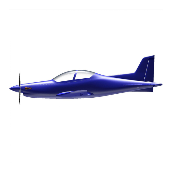
- Page 1 ASSEMBLY MANUAL AND USER GUIDE Pilatus PC-21 By 3D AEROWORKS...
- Page 2 OVERVIEW: This replica of the Pilatus PC-21 is designed for quick and easy construction and printed using light-weight PLA (LW-PLA). For best results the canopy should be printed with clear PLA, and the motor mount and propeller assembly in regular PLA or PETG. A semi scale propeller and hub is included in the plans designed to suit the 2804 2300kv outrunner (7x5) in 2 blade configuration.
- Page 5 REQUIRED TOOLS: KNIFE LIGHTER SANDPAPER (MEDIUM GRIT) PLIERS CA GLUE SCREW DRIVERS FILE OR RASP REQUIRED COMPONENTS: X1 2804 2300KV MOTOR (or similar) X1 12AMP or 20AMP ESC X1 950MAH 2S LIPO OR SIMILAR X4 3.7G MICRO SERVO BAMBOO SKEWERS 3MM HEAT SHRINK TUBE 3mm X2 10mm X 10mm X 2mm MAGNET (ROUND) X10 MICRO HINGES (OPTIONAL)
- Page 6 ASSEMBLY INSTRUCTIONS After all parts have been printed, some may require to be cleaned as LW-PLA is prone to stringing. Do this by gently sanding back the rough sections with a file, sandpaper or blade until the surface is smooth. All faces which are to be glued to other parts need to be given a light sanding (scuff the surface) to assist with glue adhesion.
- Page 7 Cut 15mm sections of skewer and place into alignment holes in the fuselage sections. NOTE - It may be required to open up the holes a small amount if the fit is too tight. Do this by using a 3mm drill bit. Gently spin it in reverse as you insert it into the hole. This will ensure the bit does not tear the print.
- Page 8 From part “fuse 3” remove the inner section of the lead tunnel with a knife or heated metal rod to allow the servo lead for the aileron to pass through. (refer image) Test fit the hinges in the hinge slots for each control surface and its parent part, this will make gluing the control surface easier when the time comes.
- Page 9 Place a drop of CA in the hinge slot of the control surface and insert the hinge. Be sure that the hinge is perpendicular to the control surface. Then bend the hinges to 90deg back and forward a few times to make sure they are appropriately loose. (the outer aileron and elevator hinge may need to be trimmed).
- Page 10 Bend a section of 1mm steel wire to connect the elevators together. Test fit the wire and the elevators connection to the horizontal stabilisers before gluing the wire to the elevators, or the elevators to the tail plane. There should be un-obstructed travel. Glue the rudder, elevators and ailerons in place.
- Page 11 Cut four 15mm sections (2 per wing) of skewer. Insert the 15mm sections into the wings. These will assist in aligning the wings when joining to the fuselage. Glue the wings to the fuselage NOTE – if using 3mm x 0.6mm carbon strip, now is the time to install it.
- Page 12 Using an appropriate length of skewer with 1mm steel wire on each end covered in heat shrink tubing, connect the elevator and rudder to their relative servo. Elevator = left side Rudder = right side Install the magnets to both the fuselage and the canopy using CA.
- Page 13 Install the desired motor mount to the fuselage using m2 screws. The mount holes may need to be pre-drilled with a 2mm drill bit. Wire up the ESC to the motor. The esc is intended to sit below the battery floor with the wires connecting to the battery through the hole in the mid section of the fuselage floor.
- Page 14 Install the motor to the motor mount. The motor mount holes may need to be pre-drilled with a 3mm drill bit. Fit the propeller hub to the motor and screw in the blades using m2 x 10mm screws. Then secure the spinner to the hub. The propeller blades will need to be pre-drilled with a 2mm drill bit for ease of fitment.
- Page 15 BALANCING AND CG The ballast lead required should be placed in the hollow section of fuse 1. NOTE! Balancing needs to be done with the propeller attached. See below Fit the battery using Velcro as required and balance the aircraft inverted on the CG marking points located 60mm aft of the leading edge at the wing root.
- Page 16 RANGE OF TRAVEL: NORMAL FLIGHT: Elevator +/- 10mm Rudder +/- 10mm Aileron +/- 8mm AEROBATIC: Elevator +/- 15mm Rudder +/- 25mm Aileron +/- 15mm LAUNCHING: It was found that the safest and most successful launch technique for this model was the under-arm style.
- Page 17 PARTS LINKS: X1 2804 2300KV MOTOR https://de.aliexpress.com/item/32880887286.html?spm=a2g0o.productlist.0.0.138a29f3Y7bX F4&algo_pvid=95040ddc-7eca-4d17-b061-ba5ed52d7eac&algo_exp_id=95040ddc-7eca-4d1 7-b061-ba5ed52d7eac-3 X1 20AMP ESC https://www.aliexpress.com/item/32905632543.html?spm=a2g0o.productlist.0.0.293536aecw u7yT&algo_pvid=09b70550-d77e-46d3-b25e-621167aaeef6&algo_expid=09b70550-d77e-46 d3-b25e-621167aaeef6-0&btsid=0b0a556616077433274567589e7b03&ws_ab_test=search web0_0,searchweb201602_,searchweb201603_ X1 950MAH 2S LIPO OR SIMILAR https://www.aliexpress.com/item/32907577121.html?spm=a2g0s.9042311.0.0.30714c4dJd4d X4 3.7G MICRO SERVO https://www.aliexpress.com/item/32965734270.html?spm=a2g0o.productlist.0.0.57d95e97a WNNAJ&algo_pvid=4824ea1c-06ed-43e8-b6c7-9737d1226dbe&algo_expid=4824ea1c-06ed -43e8-b6c7-9737d1226dbe-0&btsid=0bb0623415991458444523660eb7bd&ws_ab_test=sea rchweb0_0,searchweb201602_,searchweb201603_ X2 BAMBOO FOOD SKEWERS (3mm diameter) HEAT SHRINK TUBE 3mm https://hobbyking.com/en_us/turnigy-3mm-heat-shrink-tube-black-1mtr-1.html?queryID=c16c 094bb26b18e39fabcb12a93a96cb&objectID=46911&indexName=hbk_live_magento_en_us_ products...
- Page 18 X4 10mm X 10mm X 2mm MAGNET (ROUND) https://www.aliexpress.com/item/1005001362617359.html?spm=a2g0o.productlist.0.0.5da36 07dAATh5j&algo_pvid=b9e32b8a-0d4f-469a-b838-b478442dda50&algo_expid=b9e32b8a-0 d4f-469a-b838-b478442dda50-0&btsid=0bb0623a15991797178681785e1811&ws_ab_test=s earchweb0_0,searchweb201602_,searchweb201603_ X10 MICRO HINGES https://hobbyking.com/en_us/super-light-pivot-round-hinges-d2xw8xl24mm-12pcs.html VELCRO – (local hardware store) X2 x 200mm carbon strip 3mm x 0.6mm (optional) https://www.aliexpress.com/item/32576381076.html?spm=a2g0o.productlist.0.0.4e922cc3nR 6757&algo_pvid=500714e5-ce74-4e52-a1b0-e349cac3f595&algo_expid=500714e5-ce74-4e 52-a1b0-e349cac3f595-7&btsid=0bb0623e15991463277515177efc08&ws_ab_test=searchw eb0_0,searchweb201602_,searchweb201603_ m2 x10mm screws https://www.ebay.com.au/itm/400PCS-M2-M2-6-Pan-Head-Self-Tapping-Screws-Assorted-Kit -Stainless-Steel-Black/254399626404?hash=item3b3b663ca4:g:CLEAAOSwQLZdsqkd&frce ctupt=true...
- Page 19 Thank you for supporting us! We hope you enjoy many hours of flying your micro PC-21. If you have any questions regarding the build process or set-up of your model, please contact us at: Aeroworks3d@outlook.com...
Need help?
Do you have a question about the Pilatus PC-21 and is the answer not in the manual?
Questions and answers