Table of Contents
Advertisement
Technical Manual
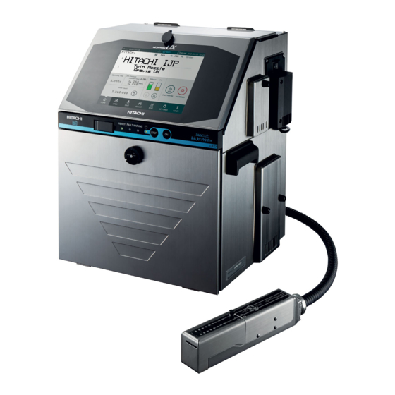
INK JET PRINTER FOR INDUSTRIAL MARKING
HITACHI Printer
Thank you for purchasing the Hitachi IJ Printer Model UX Twin Nozzle.
This printer employs a noncontact, ink-jet method to print onto a print target.
This instruction manual describes the basic operating procedures, maintenance procedures, and other detailed
handling procedures of the Hitachi IJ Printer Model UX Twin Nozzle.
If the printer is improperly handled or maintained, it may not operate smoothly and may become defective or
cause an accident. It is therefore essential that you read this manual to gain a complete understanding of the
printer and use it correctly.
After thoroughly reading the manual, properly store it for future reference.
IF you changed the language of screen by mistake,see "7.8 Selecting Languages" in the Instruction Manual.
Model UX Twin-Nozzle
Advertisement
Table of Contents

Related Manuals for Hitachi UX Twin-Nozzle


Summary of Contents for Hitachi UX Twin-Nozzle
- Page 1 HITACHI Printer Model UX Twin-Nozzle Thank you for purchasing the Hitachi IJ Printer Model UX Twin Nozzle. This printer employs a noncontact, ink-jet method to print onto a print target. This instruction manual describes the basic operating procedures, maintenance procedures, and other detailed handling procedures of the Hitachi IJ Printer Model UX Twin Nozzle.
- Page 2 SAFETY PRECAUTIONS ● You should observe the precautions set forth below in order to use the product properly and avoid endangering you or other persons or damaging property. For the purpose of clarifying the severity of injury or damage and likelihood of occurrence, the precautions are classified into two categories, WARNING and CAUTION, which both describe hazardous situations that may arise if you ignore the precautions and perform an incorrect handling or operating procedure.
- Page 3 SAFETY PRECAUTIONS (Continued) Installation Environment of Printer WARNING ● Ensure that there is no flame- or arc-generating device around the printer. The ink and makeup are both flammable and may cause fire. Fire can be generated by matches, lighters, cigarettes, heaters, stoves, gas burners, welders, grinders and static electricity.
- Page 4 SAFETY PRECAUTIONS (Continued) Grounding WARNING ● Ensure that all electrical wiring, connections and grounding comply with applicable cords. Properly connect the printer to its dedicated ground. Complete the above procedure to avoid electrical shock hazards. ● When welding, keep enough space between the IJ printer and the welding work area to prevent the arc from starting a fire.
- Page 5 SAFETY PRECAUTIONS (Continued) Ink and Makeup Handling WARNING ● When charging a refill of ink or makeup, exchanging ink, or otherwise handling ink or makeup, take enough care not to spill ink or makeup. If you spill any ink or makeup by mistake, wipe it off neatly and promptly with wiping paper or something similar.
- Page 6 CAUTION ● Only persons who have completed an operator training course for Hitachi IJP can operate and service the printer. If the printer is operated or serviced incorrectly, it may malfunction or break down. ● Do not attempt to make repairs for any purpose other than operation or maintenance.
- Page 7 SAFETY PRECAUTIONS (Continued) Related Regulations WARNING ● Never drain the ink or makeup waste solution into a public sewer system. Waste disposal must comply with all appropriate regulations. Consult the appropriate regulatory agency for further information. ● The printer must be managed in compliance with all appropriate regulations. Read and understand the appropriate Safety Data Sheet (SDS) before using any ink or makeup.
- Page 8 SAFETY PRECAUTIONS (Continued) WARNING <Keep all fire away.> ○ Ink and Makeup are flammable. ○ All fire must be kept away from the machine. ○ Spilled Ink and Makeup must be wiped off and dried up immediately. <Caution when handling Ink/Makeup> ○...
-
Page 9: Table Of Contents
CONTENTS 1. DELIVERED GOODS ......1-1 2. INSTALLING PRECAUTIONS ..... 2-1 3. - Page 10 5.3.7 Calendar Conditions Transmission........5-25 5.3.8 User Pattern Character Transmission .
- Page 11 6.9 Adjusting the pressure ........6-28 6.10 Excitation V adjustment .
-
Page 12: Installing Precautions
2. INSTALLING PRECAUTIONS WARNING ● Ensure that there is no flame- or arc-generating device around the printer. The ink and makeup are both flammable and may cause fire. Fire can be generated by matches, lighters, cigarettes, heaters, stoves, gas burners, welders, grinders and static electricity. - Page 13 (9) When installing the print head and print head cable, comply with the following conditions or it will increase the risk of degraded performance of the ink supply and ink recovery behavior. When positioning the end of the print head above the printer main body installation surface,ensure that the distance between the end of the print head and the installation surface does not exceed 1.5 m.
- Page 14 (13) When connecting an exhaust duct to the printer, install a damper and adjust the wind velocity at the intake port to 0.3 to 0.5 m/s. (Use an anemometer for verification. If the wind velocity is too high, the makeup consumption increases.) Connect a duct to this port (50 mm in diameter).
-
Page 15: Installation Check Items
3. INSTALLATION CHECK ITEMS 3.1 Print head air purge If the makeup remains in the electrode section after cleaning or if you use the IJ printer at a high humidity, moisture condensation may occur within the print head, causing leakage from the deflection electrode section. It is also important to remember that dust or splashed ink accumulation on the deflection electrode section may cause leakage. -
Page 16: Setting Functions Which Can Be Performed
3.2 Setting functions which can be performed (1) Functions ●Sets whether or not each function is enabled or disabled for each login user. ●The operation buttons of disabled functions are not displayed or the screen cannot be entered. ●”User conditions setup” and “Using environment setup” can be started when the administrator logs in. ●The function restrictions state can be checked at the function restrictions screen. - Page 17 (2) Operation The administrator is logged in. Press Login management of the Environment setup menu. The Login management menu is displayed. Log in as a user with administrator rights when User conditions setup or Using environment setup are not displayed on Login management menu. Login management menu [Stop ] 2018.07.07 12:45...
- Page 18 Select user5 . “user5” settings are displayed. [Stop ] 2018.07.07 12:45 User conditions setup Com=0 Modifies the user Makeup name. user5 ID:5 Startup Manual Administrator rights Users Administrator HOME Displays the kind protect Edit message access of administrator Select message access protect rights.
-
Page 19: Password Protection Will Be Canceled In Units Of Print Item
3.2.1 Password protection will be canceled in units of Print item (1) Overview ●When Password protection is valid, it can be canceled in units of Print item. ●When Administrator logs in, Password protection can be canceled. (2) Operation ●The character input is made as follows. (Column 1) (Column 2) 18.... - Page 20 Press Edit message on “Change message” screen. “Edit message” screen will be displayed. Edit message [Stop ] 2018.07.07 12:45 Com=0 Message name[SAMPLE 1 ] Makeup Manual Startup − + USE BY 18.07.07 HOME USE BY 18.07.07 Column 1 0 : A B Item 101 → Char. count 《 ← → 》 16 / 500 USE BY ・...
- Page 21 Press Next item . The cursor moves to Column 2. Password protection [Stop ] 2018.07.07 12:45 Com=0 Message name[SAMPLE 1 ] Makeup Startup Manual − + USE BY 18.07.07 HOME USE BY 18.07.07 0 : A B → Twin pro- access tect access protect all Back Press access . Password protection where the cursor is placed will be canceled and the character’s shade will disappear.
-
Page 22: Selecting Login User When Power Is Turned On
3.3 Selecting login user when power is turned on (1) Functions ●Sets whether or not to select a user which logs in when power is turned on. Possible login methods Login method “Disable” Login method “Enable” Immediately displays the Print Selects the user which logs in when Operation when power is description screen when the power... - Page 23 Press Using environment setup . The Using environment setup screen is displayed. When "Disable" is selected, Using environment setup [Stop ] 2018.07.07 12:45 Com=0 the Print description screen Makeup is immediately displayed when the power is turned on. Disable Enable Login method Startup Manual Default login ID : 1...
-
Page 24: The State Where The Administrator Login Is Returned Automatically
3.4 The state where the administrator login is returned automatically (1) Function details ●In case that Administrator logged in to printer and left the screen untouched for 15 minutes, the new function will switch the login condition to Users from Administrator. ●Flow diagram below shows the steps of switching to User login condition. - Page 25 (3) Operation Log in the administrator. Press Login management of the Environment setup menu. The Login management menu is displayed. 2018.07.07 12:45 Login management menu [Stop ] Com=0 Makeup Manual Startup Login history Select login user Password setup Sets function HOME restrictions for each user.
- Page 26 Press Administrator Automatic Deselect Enable . When "Disable" is selected, [Stop ] 2018.07.07 12:45 Using environment setup Com=0 the Print description screen Makeup is immediately displayed when the power is turned on. Disable Enable Login method Startup Manual Admin Default login ID : 1 HOME Administrator Automatic Deselect Disable...
-
Page 27: Human Machine Interface [Hmi] Setup
3.5 Human Machine Interface [HMI] setup (1) Function ● When you log in as a general user, you can set "Human Machine Interface [HMI]" to either Previous or New . ● It is set by "Human Machine Interface [HMI]" on "Touch screen setup" screen. This item is available for display/selection when the administrator user logs in. - Page 28 Press “Display Item” button. List of display items is then displayed. Touch screen setup [Stop ] 2018.07.07 12:45 Com=0 Display OFF in 3 min. Keyboard layout QWERTY Disable Ink pressure Enable ICON Display YYYY.MM.DD Clock display format Ink filter replacement Display Non display Confirmation window for Manual Control Menu Recovery filter replacement...
-
Page 29: Electric Signal Connection
4. ELECTRIC SIGNAL CONNECTION 4.1 Wiring precautions (1)If noise enters the IJ printer from the outside, there is the danger of erroneous operation or trouble. To improve noise resistance, perform wiring work as follows: Separate the power cable to the IJ printer from other power lines for powering use (especially, power line for a speed control inverter, etc.). - Page 30 (3) Precautions related to welding current of welder Signal (weak electric) ground and frame ground are connected because the ink drops of the IJ printer are electrically charged. Ink column Charge electrode The ink drops are electrically charged by impressing a Nozzle voltage between the charging electrode and ink column as shown at the left.
-
Page 31: Input/Output (I/O) Signal Connection
4.2 Input/output (I/O) signal connection 4.2.1 Wiring the I/O line Open the top cover and run the I/O line wiring from the lead-in port on the side and connect it to external connection terminal boards 1 and 2 and the external communications connector inside the IJ printer. CAUTION When performing wiring work, always turn off the power. - Page 32 Lead-in port connection method Set screw [Lead-in port] Cable seal block Cable seal block Seal Lock nut Cable Seal Cable Remove the set screw and remove Remove the lock nut. the cable seal block from the body. Pass the cable through as shown Separate the cable seal block.
-
Page 33: Connection To Input/Output (I/O) Terminals
4.2.2 Connection to input/output (I/O) terminals [Overview of Terminals and Connectors] The terminal block and connectors for wiring are located behind the electrical access door (upper front panel door). External connection terminal block1 Communication connector CAUTION Faulty wiring causes the substrate breakdown. Before wiring, be sure to confirm the terminal signal. - Page 34 [ Connection to the external connection terminal block (TB1 of EZJ127 board) ] ● The I/F signal with conveyor is connected. ● NPN/PNP interface can be selected for the print target detector and a part of I/O signals. ● Totem pole/Open collector(NPN) can be selected for the encoder signal. Name Input/output Remarks...
- Page 35 EZJ127 board Input : PNP Input : NPN Output : PNP Output : NPN Input : NPN Input : PNP Output : PNP Output : NPN (Precautions when using combination of NPN/PNP interfaces) ● Use either NPN or PNP interface for input/output signals #4 to 5 and #14 to 23. Do not use a combination of the interfaces for these input/output signals.
-
Page 36: Input/Output (I/O) Specifications
4.3 Input/output (I/O) specifications When handling external signals, observe the voltage, current, and time given in this manual. Operation is not guaranteed if external signals are not handled properly. If external signals are not handled properly, it may damage the board and operation is not guaranteed. [Input / Output Signal Specifications] (1) Input signals (external device →IJ printer) Electrical characteristics... -
Page 37: Print Target Detector Input
(2) Output signals (IJ printer →external device) Signal name Function Electrical characteristics Operates when the IJ printer is ready for Open collector (NPN) 1 Ready ● Sink current: 20 mA max. printing or in input mode. ● ON voltage: 0.5 V or less 2 Fault Operates when the IJ printer is fault state. - Page 38 (c) When NPN interface and dedicated power (d) When PNP interface and dedicated power supply are used supply are used Power Power DC24V DC24V DC24V Signal Signal Signal Signal 24VDC dedicated 24VDC dedicated power supply power supply Print target detector Print target detector ・SW1 "3": ON ・SW1 "3": OFF...
- Page 39 (3) Print target detector signal noise filter (a) IJ printer built-in noise filter setting. This function uses to filter the normal noise generated at the print target detector signal and noise generated by water drops, etc. with CR. The target sensor filter function (See “4.14 Set the print specifications” in the Instruction Manual) is effective against sensor chattering.
- Page 40 (4) Relationship between print object detection signal and printing operation 3 ms min. 3 ms min. Print object OFF ON detection signal Printing operation Printing Printing *Printing preparation time (Print start delay adjustment = 0) (Printing interval) *: The printing preparation time minimum Reference of printing preparation value varies with the print dot matrix, ink Nozzle diameter...
-
Page 41: Product Speed Matching Function Using A Rotary Encoder
4.3.2 Product speed matching function using a rotary encoder The product speed matching function is used when the speed of the print target or the conveyor carrying the print target changes while the IJ printer is printing. If this function is not used, when the speed changes, the width of the printed characters may change and the characters may be difficult to read. - Page 42 (3) Encoder wiring and setting of SW1 on EZJ127 board when used with a dedicated power supply. ● Wiring used for a dedicated power supply differs according to output interface of the encoder, but can be the same depending on power supply voltage. (c) When open collector output and dedicated power (d) When totem pole output and dedicated power supply are used...
- Page 43 4.3.2-3 Method of calculating the conditions which allow product speed matching Calculate to find whether the Ink drop use and division factor are the conditions which allow product speed matching, based on the following. Print quality improves as the calculation shown below is performed and the Ink drop use becomes smaller. In addition, when changing Ink drop use, check the print quality.
- Page 44 (5) When a rotary encoder is used, the print character width cannot be changed by changing the IJ printer character width set value. When the print character width must be changed, a device (timing belt, pulley, etc.) which varies the conveyor speed and rotary encoder speed synch signal pulse frequency ratio must be installed.
- Page 45 Example 2: Calculate the diameter ratio (RT) of the pulley when the rotary encoder is connected to the conveyor through a pair of pulleys. Conveyor Pulley B Pulley A Diameter Encoder <Calculation conditions> ●Dot font × 7 dots (horizontal direction 5, vertical direction 7) ●Inter-character space : 1 dot (1 scan) ●Inter-character interval...
-
Page 46: Input Function
4.3.3 Input function The IJ printer can be controlled by inputting print stop, remote operation (“Startup”, “Shutdown”, “Reset”, “Deflection voltage control”) and reciprocative print switching to pins 4, 5, and 14 to 18 of TB1 by switch or contact signal from the outside. Internal circuit diagram (a) NPN interface input (no voltage input) Print stop... - Page 47 ●No-contact (transistor) Withstand voltage : 30VDC or greater Maximum drive current : 6mA or greater Residual voltage : 2V or less Leakage current : 0.1mA or less Drive method : Open collector ● Contact signal Use a relay whose contacts chattering at contacts ON/OFF is 2.0ms or less. 4.3.3-1 Print stop signal input [Function] This function prevents printing from the outside.
- Page 48 4.3.3-3 Remote startup signal input [Function] This function inputs the same operations as the IJ printer operation state operation keys (“Startup”, “Shutdown”, “Reset”, “Deflection voltage control”(standby state and Ready to print state switching)) by external switch or contact signal. (a) Judgment conditions (a-1) Remote signals in general Remote signal ON time t1 shall be 100ms or greater.
- Page 49 (a-3) “Reset signal” Input this signal when the fault signal is ON. In addition, after signal input, check if “Fault” is cleared. Turn on the “Reset signal” 30 seconds or longer after the IJ printer power is turned on. The time until the fault is cleared after the “Reset signal” is input t5: within 100ms Reset signal Fault signal...
-
Page 50: Output Function
4.3.4 Output function The state of the IJ printer is monitored by connecting the print output (“Print-in-progress” or “Print.complete”), online output, Ready, Fault, and Warning signals to pins 10 to 23 of TB1. (No-contact (transistor) output) Internal circuit diagram (a) NPN interface output (no-voltage output) Print output Online output Ready... - Page 51 4.3.4-1 Print output signal (NPN/PNP interface output : TB1-19) [Function] This function outputs a signal to the outside at IJ Printer Print.complete or Print-in-progress. (a) Print-in-progress and Print.complete switching Switching of the Print-in-progress and Print.complete signals is set at the User environment setup screen. (See “6.1 Set the user environment”...
- Page 52 4.3.4-6 External communication (RS-232C) External equipment is connected to the IJ printer by serial communication of RS-232C. Pin No. Name Input/Output Remarks (NC) Input Output Connect with DSR by IJ printer side. Connect with DTR by IJ printer side. Connect with CTS by IJ printer side. Connects with RTS by IJ printer side.
-
Page 53: Product Speed Matching Function Without A Rotary Encoder
4.3.5 Product speed matching function without a rotary encoder 4.3.5-1 Auto product speed matching function Auto product speed matching function is used for detecting the change of speed of the conveyor carrying print target using the print target detector connected to the IJ printer, and prints each vertical line of the print according to the change of speed in the same way as the Speed matching function using a rotary encoder. -
Page 54: Communication
5. COMMUNICATION 5.1 Overview The functions described in this document are used to transmit printings and their registration numbers and enter them into the IJ printer with an external device connected to the IJ printer via an RS-232C serial communication line. (1) Printings transmission ●... - Page 55 (7) User pattern character transmission ● This function is used to transmit a user pattern and enter it into the IJ printer. ● A transmitted user pattern can be edited using the "Create user pattern" function, which is provided as an auxiliary function.
-
Page 56: Setting Communication Environment
5.2 Setting Communication Environment 5.2.1 Setting Communication Environment (1) Overview Function Description Default ● Comm. port is OFF : Offline mode when the power is turned on. ● Comm. port is ON : Online mode when the State at power-up power is turned on. - Page 57 (2) Operating procedure Press Communication environment setup from the Environment setup menu. The "Communication environment setup" screen appears. Comm. env. setup [Stop ] 2018.07.07 12:45 Com=0 Makeup State at power-up Comm. port in ON Communication and signal error Warn. Fault Manual Startup <Transmission condition by port>...
-
Page 58: Transmission Specifications
5.2.2 Transmission Specifications (1) Communication method : Half duplex (2) Startup method : Started up by host (3) Synchronization method : Asynchronous (4) Transmission method : Bit serial transmission (5) Baud rate : 150, 300, 600, 1,200, 2,400, 4,800, 9,600, 19,200, 38,400, 57,600, 115,200(bps) (6) Codes transmitted : Alphanumerical characters, symbols, dedicated characters,... -
Page 59: Transmission Sequences
5.3 Transmission Sequences 5.3.1 Common Transmission Sequences (1) Basic transmission operation. When ENQ and ACK are present: External device Text IJ printer When ENQ is omitted: External device Text IJ printer (2) When DC2 (retransmission) code is used (When no response is received though ENQ has been issued and yet the contents of print area switched) External device Text... -
Page 60: Printings Transmission
(9) Any data transmitted by communication (print contents, print specifications, print format, and user pattern) is not stored except in the following cases. [Conditions for storing the data] When the ink is stopped after communication by the Shut down key or a stop signal. At 01 minute of every hour. - Page 61 5.3.2-2 Item number Item number Code Item number Code Item number Code Item number Code Item number Code Item number Code Item number Code Item number Code Item number Code Item number Code ● The order of print items is indicated below. (3-column example) Circled number: Item number Row1 Row2 5.3.2-3 Printings...
- Page 62 5.3.2-4 Character codes (1) 2-byte code (number of communication bytes: 1-byte mode) ● For 1-byte mode, 2-byte codes are sandwiched between "SI" and "SO." ● One character High-order Low-order byte byte ● Two or more characters High-order Low-order High-order Low-order High-order Low-order byte...
-
Page 63: Print Data Recall Transmission
5.3.3 Print Data Recall Transmission 5.3.3-1 Text Classification ESC2 Header 20H 1000s place 100s place 10s palce Units place Print data message number (0001 to 2000) [Existing machine message] Existing machine message can also be used. Header 56H 100s place 10s place Units place Print data message number (001 to 999) -
Page 64: Print Data Registration Transmission
5.3.4 Print data registration transmission 5.3.4-1 Text ● Specifies message number Classification ESC2 Header 21H 1000s place 100s place 10s place Units place Print data message number (0001 to 2000) ● Specifies registration No. and message name. Classification ESC2 Header 21H 1000s place 100s place 10s place... - Page 65 5.3.4-2 Message name (1) message number specified ● A message name is automatically attached when print data is registered. ● Based on the message name displayed in the upper left hand corner of the screen, the last 4 digits are replaced with the message number and used as the new message name.
-
Page 66: Print Condition Transmission
5.3.5 Print Condition Transmission 5.3.5-1 Text (1) Line count / print format uniformity ESC2 Header 22H Classification 31H ● Line count and print format are made uniform for all print items. ● Line count of all rows are made uniform based on the first row. ●... - Page 67 (4) Print format text ● Line count and Line spacing Classification ESC2 Header 22H Line count Line spacing Line count (1 to 5) Line spacing (0 to 4) (5 lines : 0 to 2) ● Character size and inter-character space Classification ESC2 Header 23H...
- Page 68 [Existing machine message] Existing machine message can also be used. ● Line count and Line spacing Character size Header 22H Line count Line spacing × 30H:5 × × 31H:5 × Line count (1 to 5) Line spacing (0 to 2) 32H:7 ×...
- Page 69 ● Character width Classification ESC2 Header 25H 1000s place 100s place 10s place Units place Character width (0000 to 3999) ● Character orientation Classification Character ESC2 Header 25H orientation Character orientation (0 to 3) ● Print start delay Classification ESC2 Header 25H 1000s place 100s place...
- Page 70 ● Target sensor filter Classification ESC2 Header 25H Division Division (1:time setup, 2:until end of print) ● Target sensor filter setting value Classification ESC2 Header 25H 1000s place 100s place 10s place Units place Value (0000 to 9999) ● Ink drop charge rule Classification ESC2 Header 25H...
- Page 71 [Existing machine message] Existing machine message can also be used. ●Character height Header 30H 10s place Units place Character height (00 to 99) ● Character width Header 31H 100s place 10s place Units place Character width (000 to 199) ● Character orientation Header 32H Units place orientation...
- Page 72 5.3.5-2 Text setup rules (1) Line count ● When you change the line count for a print item in a certain column, you must also set the line count for the other print items that belong to the same column. (Example) Setting items 7 and 8 to one line Transmit the line count consecutively to items 7 and 8.
- Page 73 (4) Bar code use and bar code type ● Two or more bar code types can coexist. ● When bar code set up is completed for a print item, its inter-character space can not be changed. (The inter-character space need not be transmitted in this case.) ●...
-
Page 74: Free Layout Transmission
5.3.6 Free Layout Transmission 5.3.6-1 Overview ● When Format setup is "Free layout", the selected print item can be moved individually. ● Free layout transmission shall be made independently. Free layout transmission can NOT be transmitted with Print format or Print specification or Print description. ●... - Page 75 (2) Specify Horizontal/Vertical directions and move ● Specify the number of dots for moving and the print item will be moved. ● Horizontal and Vertical move Item Classification ESC2 Header 24H (Contd.) number Item number (1 to 100) Horizontal 10000s 1000s place 100s place 10s place Unit place...
- Page 76 5.3.6-3 Example of Free layout transmission (1) Specify Horizontal/Vertical coordinate and move STX ESC2 Header, Item No. Horizontal (X) Vertical (Y) classification coordinate coordinate [Transmission result] Print item 5: Horizontal (X) coordinate will be set to 120 and Vertical (Y) coordinate to 25. STX ESC2 Header, Item No.
- Page 77 (2) Specify Horizontal/Vertical directions and move STX ESC2 Header, Item No. Horizontal (X) direction Vertical (Y) direction classification [Transmission result] Move print item 10 rightward by 100 and upward by 20. - - STX ESC2 Header, Item No. Horizontal (X) direction Vertical (Y) direction classification [Transmission result] Move print item 20 leftward by 20 and downward by 5.
-
Page 78: Calendar Conditions Transmission
5.3.7 Calendar Conditions Transmission 5.3.7-1 Text (1) Calendar Conditions Transmission ● Offset Calendar Units Classification ESC2 Header 28H Type 1000s place 100s place 10s place block No. place Offset Calendar block No. Type (1 to 8) 30H : Year 31H : Month Offset setting range 32H : Day Setting item... - Page 79 (2) Count Conditions Transmission Count Setting ESC2 Header 2CH Classification block No. value Calendar block No. (1 to 8) Classification Item name Setting value Initial value Character code Range 1 Character code Range 2 Character code Update setting range (In progress) 000000 to 999998 Update setting range (Unit) 000001 to 999999 Increment setting range...
- Page 80 [Existing machine message] Existing machine message can also be used. (1) Initial value, Range, Jump from, Jump to, Reset Header 80H Item No. Type Setting value Code of type Initial value Range 1 Range 2 Jump from Jump to Reset ASCII ASCII is hexadecimal number.
-
Page 81: User Pattern Character Transmission
5.3.7-3 Example of count conditions transmission (1) Example of reset STX ESC2 Header, Count Reset value 00000 block No. classification [Transmission results] Defines reset value 00000 for count block 1. 5.3.8 User Pattern Character Transmission 5.3.8-1 Text ● When the number of communication bytes is set to "1" for communication Character ESC2 Header 32H Classification... - Page 82 ● For pattern data composition purposes, the data is arranged in successive order, beginning from the bottom left, from bottom to top and from left to right. b) Pattern data example × [For a character size of 5 Unusable area 4 5 6 7 8 ●...
- Page 83 5.3.8-4 Character codes For character code designation, either ASCII codes or 2-byte codes are used. (1) ASCII codes (when the number of communication bytes is 1) User pattern character ASCII D9 DA DB DC DD DE DF User pattern character ASCII EA EB EC ED EE User pattern character...
-
Page 84: On-Line/Off-Line Transmission Procedure
5.3.9 On-line/off-line Transmission Procedure 5.3.9-1 Text (1) Change to online ESC2 Header 73H (2) Change to offline ESC2 Header 74H [Existing machine message] Existing machine message can also be used. (1) Change to online Header 79H (2) Change to offline Header 7AH ●... -
Page 85: Remote Operation Transmission
5.3.10 Remote Operation Transmission 5.3.10-1 Text Type 30H:Operation start ESC2 Header 72H Type 31H:Operation stop 32H:Deflection voltage control (ON) 33H:Deflection voltage control (OFF) 34H:Fault clear [Existing machine message] Existing machine message can also be used. Header 71H Type 5.3.10-2 Types of control Types of control for operation Type Content... -
Page 86: Time Control
5.3.11 Time control 5.3.11-1 Text (1) Date/time setup transmission ● Current time Header 1000s 100s Units Units Classification ESC2 place place place place place place (Contd.) Month Year Units Units Units Units place place place place place place place place Hour Minutes Second... - Page 87 [Existing machine message] Existing machine message can also be used. (1) Date/time setup transmission ● Current date/time Header 72H 1000s place 100s place 10s place Units place 10s place Units place (Contd.) Yaer Month 10s place Units place 10s place Units place 10s place Units place...
-
Page 88: Print Item Deletion Transmission
5.3.12 Print item deletion transmission 5.3.12-1 Overview ● The first print item will be left. ● All the print message in the first print item will be deleted. ● The print format of the first print item will be kept. ●... -
Page 89: Code Tables
(7) Calendar character code ● Set "calendar block starting character"as the first character and set "calendar block ending charater" as the last character. (Example) Calendar block Y Y M M D D Calendar block end character Calendar character Calendar block start character Total number Day of Yaer... - Page 90 (Example 2) Example of when setting 2 calendar blocks to print item 1 02H 10H 31H 0FH F2H 60H F2H 50H F2H 51H F2H 51H F2H 52H F2H 72H 0EH (Contd.) Start STX DLE Calendar Calendar Calendar Calendar chracter chracter Calendar block 1 41H 42H 43H 0FH F2H 62H F2H 52H F2H 53H F2H 73H 0EH 03H Start...
- Page 91 Example of when performing printings transmission of count character (Example 1)Example of when setting a count block to print item 1 Start chracter Count Count End chracter Count block [Transmission results] : Count block range C C C C Print item1 : Count character (Example 2)Example of when setting 2 count blocks to print item 1 02H 10H 31H 0FH F2H 6AH F2H 5AH F2H 5AH F2H 5AH F2H 5AH F2H 7AH 0EH...
-
Page 92: Header Table
5.4.2 Header Table ESC2 Header Classification Data Type Header Classification Data section count Recall Message number 0001 to 2000 Message number 0001 to 2000 Registration Message name 1 to 12 Message name: Max 12 digits Line count, print format uniformity Line count : 1 to 6 Line count/Line spacing Line spacing: 0 to 4 (5 or 6 lines : 0 to 2) - Page 93 Data Type Header Classification Data section count Calendar block : 1 to 8 Type : 0 to 4 Offset Offset : Yaer 0000 to 0099 (Year / month / day / hour / Month 0000 to 0099 minute) 0000 to 1999 Calendar Hour -023 to 0099...
-
Page 94: Communication Timing
5.5 Communication Timing 5.5.1 Signal Timing (1) In overwrite-protected mode On-line Off-line External device IJ printer ACK ACK ACK ACK (No signal output) Not ready Readiness Ready for for reception reception reception Print start signal Printing operation (a) When the IJ printer is off-line ●... - Page 95 (e) When a data transmission is aborted (the transmission of up to the ETX code is not completed) ● The IJ printer printings remain unchanged. For data retransmission, perform either of the following procedures. Transmit the DC2 (retransmission) code to the IJ printer. Press the Comm On/Off buttun to enter the off-line mode, and then switch back to the on-line mode.
- Page 96 (3) Switching print data with no occurrence of fault "Print data changeover in progress M" The following shows the method of use with no occurrence of "Print data changeover in progress M" when switching the print contents during transmission: (a) Print timing schematic diagram Print target Print target Print target...
-
Page 97: Response Time
5.5.2 Response Time 5.5.2-1 Time interval (T1) between external device communication and IJ printer response External device ……… IJ printer Baud rate (bps) T0 Maximum time (ms) 150 to 1200 2400 to 115200 (1) When Print format is set to "Individual" or "Overall" Time interval T1 when Print format is set to "Individual"... - Page 98 (2) When Print format is set to "Free layout" Time interval T1 when Print format is set to "Free layout" T1 Maximum time (ms) No. Transmission type Conditions Remarks Within 24 items 25 items or more The print message transfer ACK condition is t=fixed.
- Page 99 5.5.2-2 Time interval (T2) between IJ printer response and printing start External device IJ printer 5ms (*7) Print start signal Printing operation (1)When Print format is set to "Individual" or "Overall" Time interval T2 when Print format is set to "Individual" or "Overall" T2 Minimum time (ms) Transmission type Conditions Remarks...
- Page 100 Time T2 when there is a data matrix, QR code and GS1 DataBar setting T2 Minimum time (ms) Barcode type Character size Within 24 items 25 items or more × × N+20 Data matrix × × × 16, 18 N+40 ×...
- Page 101 *7 If the communication time interval is not sufficiently secured, it may not operate normally. *12 When there is a data matrix, QR code and GS1 DataBar setting, the time is as follows: Time T2 when there is a data matrix, QR code and GS1 DataBar setting T2 Minimum time (ms) Barcode type Character size...
-
Page 102: Communication Monitor Function
5.6 Communication Monitor Function ● The contents of serial communications between the external device and IJ printer are displayed. ● Up to 3,000 bytes of data can be acquired at a time. ● When you press the Start button, the system erases monitored data and acquires new data. ●... - Page 103 (3) Explanation of USB output function. ● When you press the USB output button, the Communication description which is displayed on screen can be output to a USB memory. ● The Communication description which is displayed on screen can be output to a USB memory. when "Comm.
-
Page 104: Warning Messages
5.7 Warning Messages ● If any communication is in error, the associated warning message appears below the status display area. ● Note the message to confirm the error and then take remedial action as appropriate for the indicated error code. Warning Print description [Ready ]... - Page 105 Error Name Description Check code 014 Parity error The parity error occurred. Check the baud rate and data format. Print format code Check the print format transmission text The print format data value was illegal. error section. 016 Overrun error The overrun error occurred.
- Page 106 Error Name Description Check code ● While "Create messages" function was operating, on-line transmission was performed. ● On-line transmission was performed Create messages Check the timing of on-line error when print data which was controlled transmission. separately from data created and registered by print description screen, was present.
-
Page 107: Precautions
5.8 Precautions 5.8.1 Notes on Product speed matching Feature Use (1) If the product speed matching signal cannot be entered during printing, the printing state continues to prevail so that communication may not be established (no response can be made). If such a situation is encountered, perform procedure below. -
Page 108: Communication Buffer
5.9 Communication Buffer 5.9.1 Overview (1) Print content transmission ● The print contents received through print content transmission will not be reflected in printing immediately, but will be temporarily held in buffer. ● The print contents are fetched from the buffer one by one for each printing, and reflected in subsequent printing. -
Page 109: Description Of Functions
5.9.2 Description of Functions (1) Application procedure ● Prepare the following in advance: Preliminary Preparation Items Procedure Specify "overwrite-enabled" for communication mode on the communication environment screen. In addition, specify "t=fixed" for print message transfer ACK. Set the buffer function on the second page of the communication environment setting screen to "enable."... - Page 110 (2) Buffer ● The print content receive buffer has a queue structure (beginning with oldest data, in sequence). ● Print content is fetched from the buffer for each printing. ● Once the Ready status is set, the first print content will be fetched from the buffer. ●...
- Page 111 (Example 3) When offline is restored during normal operation, and printing is subsequently performed in standard mode: Online External device IJ printer Ready Printing (Example 4) Buffer repeat count is 2. External device IJ printer Printing (Example 5) Timing of Fault : Print completed, Data count when error occurs : 2 External device IJ printer Printing...
-
Page 112: External Communications
5.9.3 External Communications 5.9.3-1 Transmitting print contents (1) Function ● The received print content will not be reflected in printing immediately, but temporarily held in buffer. Item External device Content IJ printer ● To facilitate operation, first input fixed characters that do not need to be changed, and then transmit only the print items to be changed. -
Page 113: Errors
5.9.4 Errors (1) Errors during external communications Errors during print content transmission and print data call-up Condition Type of error NAK is returned. Not all received print contents could be held in buffer because However, this will not cause any its capacity was exceeded external communication error. -
Page 114: Circulation System Work And Adjustment
6. CIRCULATION SYSTEM WORK AND ADJUSTMENT METHOD WARNING ● Never pour the ink and makeup waste into a sewer, etc. Have the ink and makeup drainage processed by an industrial waste processor as special control industrial waste and used wiping papers and the empty container as industrial waste. -
Page 115: Circulation Control Screen Operation And Contents
6.1 Circulation control screen operation and contents 6.1.1 Circulation control screen operation Start from the Maintenance menu. Perform menu 1 and menu 2 switching using Prev. menu and Next menu . 2018.07.07 12:45 Circulation control [Stop ] Com=0 Makeup Eject ink Cleaning stop No-cleaning stop (Goes to Standby) HOME... -
Page 116: Circulation Control Contents
6.1.2 Circulation control contents ● During generation of an “Main Ink Tank Too Full” fault, input from any of the keys is not accepted. Perform operation after referring to par. “6.12 Draining ink from the main ink tank” and clearing the fault. ●... -
Page 117: Removing Inner Cover
6.2 Removing Inner Cover ● Open the Maintenance cover. ● Remove the inner cover while tilting it to the direction of an arrow and then lifting it up to the direction of an arrow Inner cover Maintenance cover ●Removing Inner Cover 6-4... -
Page 118: Replacing The Ink
6.3 Replacing the ink (1) Overview ● This operation is performed when replacing old ink with new ink. ● Consecutively performs from ink drainage to ink replacement to ink refilling. ● Do not perform this operation while ink is being ejected. Perform it after setting the IJ printer to the “Stop” state. - Page 119 a) Put the ink filter tubes down, and disconnect the recovery tube and connect it to the waste solution bottle. CAUTION ● If the waste bottle is not available at hand, a container which holds more than 1.5 liter of content shall be used. Do not use a container mode of other rhan polypropylene, polyethylene, fluororesin, glass or stainless.
- Page 120 ● [If not using the waste solution bottle] ● Connect the recovery tube to the accessory drain tube and insert it into the beaker. Recovery tube Insert Drain tube Beaker CAUTION Clean the drain tube with makeup after using. Otherwise it may be clogged with ink and cause the pressure in the recovery line to rise abnormally the next time it is used.
- Page 121 CAUTION [If using the waste solution bottle] ● During ink drainage, hold the waste solution bottle so as not to knock it over. [If not using the waste solution bottle] ● During ink drainage, hold the beaker as well as the recovery tube so as not to knock over the beaker.
- Page 122 a) Set a new ink cartridge bottle in the ink tank. Set a new cartridge bottle. CAUTION If ink is accidentally spilt, wipe it up promptly with wiping paper or something similar. In addition, do not close the maintenance cover until you are sure that the wiped portion has completely dried.
- Page 123 e) When Start/Continue is pressed, refilling of the lines with ink begins. ● After a while, ink is ejected from the nozzle. Check the position of the ink beam. ● To abort the sequence, press Abort and operate in accordance with the operation guidance on the screen.
-
Page 124: How To Correct Ink Stream Bending And Nozzle Clogging
6.4 How to correct ink stream bending and nozzle clogging WARNING ● Wear protective gear (goggles and mask). ● If the ink or makeup gets in your eyes or mouth, immediately rinse with warm water and consult a doctor. ● Perform work after confirming that there is no one in the ink ejection direction. (Perform this work by inserting the print head tip into a beaker, etc.) 6.4.1 Nozzle 1 backwash (including Nozzle 2) ●... - Page 125 Suction ends in about 1 minute and the screen returns to the Circulation control screen. ● To stop operation, press Abort . Check if ink stream bending or nozzle clogging has been repaired. ● Display the screen after the Circulation control screen. 2018.07.07 12:45 Circulation control [Stop ]...
-
Page 126: Nozzle Orifice Disassembly And Cleaning
6.4.2 Nozzle orifice disassembly and cleaning ● This is the processing method when ink stream bending or nozzle clogging is not repaired even when nozzle backwash was performed. ● Do not perform this work while ink is being ejected. Perform it after setting the IJ printer to the Stop state. - Page 127 (d) Use the tweezers to remove the nozzle orifice from the nozzle body. Notice O-ring Do not touch the ink ejection Tweezers port on nozzle orifice. Ejection port Nozzle orifice The O-ring may detach from the nozzle orifice at this time. If it does, put the O-ring in a beaker with makeup ink and take care not to lose it.
- Page 128 Use the cleaning bottle and splash a few droplets of makeup on the O-ring. O-ring Cleaning bottle Insert the nozzle orifice and use tweezers to lightly depress the nozzle orifice from the top. Notice Do not touch the ink ejection port on nozzle orifice.
- Page 129 → Press the Ink stream 1 alignment Start/Continue and confirm that bending of the stream and clogging of the nozzle have been repaired. ● Perform this operation with the tip of the print head inserted into a beaker. ● When the ink stream is way outside the gutter, cleaning of the nozzle orifice may not be sufficient. Disassemble and clean the nozzle orifice again.
-
Page 130: Stream Alignment
6.5 Stream alignment WARNING ● Wear protective gear (goggles and mask). ● If the ink or makeup gets in your eyes or mouth, immediately rinse with warm water and consult a doctor. ● Perform work after confirming that there is no one in the ink ejection direction. (Perform this work by inserting the print head tip into a beaker, etc.) This operation is performed when the nozzle or nozzle orifice has been replaced. - Page 131 Minus deflection electrode Horizontal direction Horizontal direction lock screw Plus deflection electrode adjustment screw Horizontal direction Horizontal direction Plus deflection Gutter adjustment screw lock screw electrode Minus deflection electrode Stream PRECAUTIONS Horizontal direction lock screw. Indication of the loosening [60 degree to 120 degree] ●...
-
Page 132: Cleaning The Gutter
6.6 Cleaning the Gutter ● When the ink recovery system becomes dry or clogged, the line from the gutter to the ink main tank can be cleaned by performing “Gutter cleaning”. ● Do not perform this operation while ink is being ejected. Perform it after setting the IJ printer to the “Stop” state. -
Page 133: Adjusting The Pressure
6.9 Adjusting the pressure ● Check the pressure before printing state check at the start of operation. ● Do not perform this operation in the Stop state. Perform it in the state in which ink is ejected. Open the Operation management screen. (a) New HMI (b) Previous HMI Operation management... -
Page 134: Excitation V Adjustment
6.10 Excitation V adjustment (1) Overview ● The Excitation V set value is 0 to 19. The state of the ink drops is different for each setting. ● The optimum Excitation V set value must be input to maintain good print quality. ●... - Page 135 Print data Select the contents and conditions of the characters to be printed. Print data Data to be displayed For test Prints using the currently set print description and print conditions. Prints using the following test conditions: ・Number of lines : 1 line ・Character size : 12...
- Page 136 Perform nozzle property test printing. ● When “Print trigger source” is , press Start printings . Button input When “Print trigger source” is , input the sensor signal. Sensor CAUTION ● During the nozzle property test, the state of creation of the ink drops may become poor and an “Ink Drop Charge Too High”...
-
Page 137: Ink Drop State Check Method
6.11 Ink drop state check method ● The state of the ink drops can be checked by using a magnifying glass. ● Perform this work in the Eject ink state. WARNING ● Wear protective gear (goggles and mask). ● If the ink or makeup gets in your eyes or mouth, immediately rinse with warm water and consult a doctor. - Page 138 Ink drops creation state confirmation table Ink drop shape Judgment Name Remarks A mode Good B mode Perfect High-speed small-diameter mode Allowable Two or fewer small-diameter drops Constant-speed small-diameter allowed mode Low-speed small-diameter allowed mode When the shape of the ink drops is not allowed, update to the optimum set value at par. “6.10 Excitation V adjustment”...
-
Page 139: Draining Ink From The Main Ink Tank
6.12 Draining ink from the main ink tank ● When the main ink tank full fault is generated, the ink cannot be drained by screen operation. Drain the ink and refill with new ink as follows: Disconnect the drain tube of the main ink tank as shown in the figure below and drain the ink in the tank by approximately 50 ml. - Page 140 Return the circulation system to its original state and display the Circulation control screen and press the Ink refill → Start/Continue . *Note that if operation is started without refilling the ink, a “Replenishment Time-out” fault will be generated. CAUTION ●...
-
Page 141: Testing Operation Of Solenoid Valve And Pump
6.13 Testing operation of solenoid valve and pump ● The operation confirmation of solenoid valve and pump is performed. ① ② ③ Supply valve (MV1) Replenishment valve (MV2) Recovery valve (MV3) ④ ⑤ ⑥ Agitation valve (MV4) Circulation valve (MV5) Pressure relief valve (MV6) ⑦... -
Page 142: On-Screen Reminder For Maintenance Parts Replacement
6.14 On-Screen reminder for maintenance parts replacement ● When the maintenance parts replacement period arrives, a message that informs the operator can be displayed. (Objective maintenance parts) "Ink filter, Recovery filter 1, Recovery filter 2, Air filter, Controlling air filter L, Controlling air filter R". ●... - Page 143 (3-page) Periodic replacement parts mgmt. [Stop ] 2018.07.07 12:45 Com=0 Makeup Alarm time Operation time Supply pump 10000 01000 Makeup pump 10000 01000 HOME Circulation pump 10000 01000 Recovery pump1 10000 01000 Recovery pump2 10000 01000 04800 00000 Controlling air filter L Prev.Dsp.
-
Page 144: Long-Term Shutdown
6.15 Long-term Shutdown CAUTION ● A special work is required to perform the Long-term Shutdown procedure. It is recommended to contact your local distributor and ask for the work. Should you desire to conduct the work by yourself, the cautions must be fully understood beforehand. -
Page 145: Process Prior To Long-Term Shutdown
6.15.1 Process prior to long-term shutdown (1) Overview ● This operation is the storage work performed when the IJ printer is shut down for exceeding the period indicated in Table 1. ● The storage procedure for long-term shutdown is completed by draining the ink from the ink circulation system and cleaning it with the makeup. - Page 146 Open the "Circulation control" screen, and press the Process prior to long-term shutdown key and the Start/Continue key. 2018.07.07 12:45 Circulation control [Stop ] Com=0 Makeup Eject ink Cleaning stop No-cleaning stop (Goes to Standby) HOME Nozzle 1 backwash Nozzle 2 backwash Gutter cleaning Prev.Dsp.
- Page 147 Release the ink-side Lock Pin and remove the empty ink cartridge bottle. Wipe the pipe surface of the ink reservoir up using wiping paper dampened with makeup. Be careful not to damage the pipe. Pipe Clean the circulation system. ● Perform operation in accordance with the operation guide on the screen. Circulation control [Service ] 2018.07.07 12:45...
- Page 148 Repeat steps one more time. (Perform the ink drainage four times; circulation system cleaning four times) Insert the nozzle of the cleaning bottle in the Supply Port and inject approxi- mately 100ml of makeup in the ink reservoir. Mount the supply port cap on the ink supply port. supply port cap Mount the nozzle rubber seal.
-
Page 149: Startup Process After Long-Term Shutdown
6.15.2 Startup process after long-term shutdown [Overview] ● This operation is the work for draining the makeup which cleaned the ink circulation system at "Process prior to long-term shutdown" and the work for refilling it with the ink. ● To completely drain the makeup from the circulation system, you should charge the circulation system with the ink, drain the ink, and refill the ink into the system. - Page 150 Remove the supply port cap on the ink supply port. supply port cap Operating procedure- "Process after long-term shutdown" (a) Open the "Circulation control" screen, and press the Process after long-term shutdown key then the Start/Continue key. Circulation control [Stop ] 2018.07.07 12:45 Com=0 Makeup...
- Page 151 Open the "Operation management" screen. Arbitrarily rotate the handle of Pressure-reducing valve clockwise/counterclockwise and check if the pressure changes. After confirming the change, adjust the valve and set the Ink pressure to standard setting with a tolerance of 0.002. (a) New HMI (b) Previous HMI Operation management ×...
-
Page 152: Maintenance Service
● For the IJ printer to operate smoothly, the following maintenance work is necessary. CAUTION Use Hitachi approved consumables and periodic replacement parts. Using products that are not designated by Hitachi could cause s failure in certain functions. (1) Replacement of consumables Replace the following filters according to the “Replacement guideline”. - Page 153 (4) Replacing the circulating air filter Trun off the power. Loosen the knobs (thumb screws) and remove the intake fan cover. Intake fan cover Knob (thumb Screw) Remove the old filter and set the new filter. (Please set the new filter with red-mark being invisible.) Air filter Red-mark inside Set the intake fan cover.
- Page 154 Open the Part usage time mgmt. screen (menu 2 of the Circulation control screen) and set the time of the air filter to “0”. Parts usage time mgmt. [Stop ] 2018.07.07 12:45 Com=0 Makeup Alarm display Enable Disable Alarm time Operation time Ink filter 01000...
- Page 155 (5) Replacing the controlling air filter Trun off the power. Loosen the knobs (thumb screws) and remove the intake fan cover. Remove the old filter and set the new filter. (Please set the new filter with red-mark being invisible.) Knob (thumb Screw) Air filter Intake fan cover Red-mark inside...
- Page 156 “Performance parts for repair” are parts necessary to maintain the functions of the product. Please fill in for later use. Customer memo: Useful when communicating with the service in charge. Your Hitachi sales representative: Tel: Person in charge: Your Hitachi distributor:...
-
Page 157: Schematic Diagrams
8. SCHEMATIC DIAGRAMS 8.1 Outside Dimensions ●Outside Dimensions 8-1... - Page 158 8-2 ●Outside Dimensions...
-
Page 159: Electrical Connection Diagram
8.2 Electrical Connection Diagram ●Electrical Connection Diagram 8-3... -
Page 160: Circulation System Diagram
8.3 Circulation System Diagram 8-4 ●Circulation System Diagram... -
Page 161: Tube Connection
8.4 Tube Connection <Front side> Viscosity meter Pressure-reducing valve Pressure Makeup filter sensor <Rear side> Fig.8-5 Model UX-D860 Tube connection ●Tube connection 8-5...
Need help?
Do you have a question about the UX Twin-Nozzle and is the answer not in the manual?
Questions and answers