Advertisement
Table of Contents
- 1 Ethernet Communication
- 2 Ethernet Communication (LAN Communication Modbus) Function
- 3 Preparations
- 4 LAN Cable Connection
- 5 Setting the Communication Environment
- 6 Connection Test
- 7 Modbus Communication
- 8 Data Configuration
- 9 Detail of Data Configuration
- 10 Modbus Communication Rule for IJ Printer
- 11 Examples of Transmission Procedure
- 12 Troubleshooting Guide
- Download this manual
See also:
Service Manual
First Edition
Instruction Manual for LAN Communication Modbus
Ethernet Communication
HITACHI
Printer
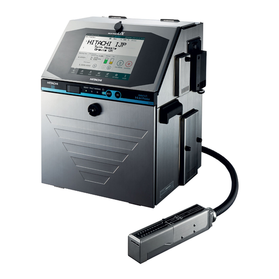
Model UX Twin-Nozzle
Thank you for purchasing the Hitachi IJ Printer Model UX Twin Nozzle.
This instruction manual describes the Ethernet communication (LAN Communication Modbus)
function. For other features of the printer, please refer to Instruction manual or Technical
manual.
If the printer is improperly handled or maintained, it may not operate smoothly and may become
defective or cause an accident. It is therefore essential that you read this manual to gain a
complete understanding of the printer and use it correctly.
After thoroughly reading the manual, properly store it for future reference.
Advertisement
Table of Contents

Related Manuals for Hitachi UX Twin Nozzle


Summary of Contents for Hitachi UX Twin Nozzle
-
Page 1: Ethernet Communication
Printer Model UX Twin-Nozzle Thank you for purchasing the Hitachi IJ Printer Model UX Twin Nozzle. This instruction manual describes the Ethernet communication (LAN Communication Modbus) function. For other features of the printer, please refer to Instruction manual or Technical manual. - Page 2 Table of Contents 1. Ethernet communication (LAN communication Modbus) function ························· 1 2. Preparations ·································································································· 2 2.1 Network connection preparations ·································································· 2 2.2 IJ Printer preparations ·················································································· 2 2.3 LAN cable connection ·················································································· 3 2.4 Setting the communication environment ························································ 4 2.4 Usage precautions ·······················································································...
-
Page 3: Ethernet Communication (Lan Communication Modbus) Function
1. Ethernet communication (LAN communication Modbus) function (1) Overview ● Function for Ethernet communication between the IJ Printer and external unit employing a LAN environment. ● Type of Ethernet communication can be selected from Modbus communication. ● Modbus communication require development of a communication program on the external unit side. -
Page 4: Preparations
2. Preparations ● If connecting the IJ Printer with external unit, use a LAN connection cable. 2.1 Network connection preparations (1) Connect to Intranet LAN Work Remarks You should obtain the IP address from the Information Systems Department of your company. You should consult with the Information Systems Department of your company concerning network settings such as gateway. -
Page 5: Lan Cable Connection
2.3 LAN cable connection Connect the LAN cable. [I/O section (with cover removed)]... -
Page 6: Setting The Communication Environment
2.4 Setting the communication environment ● Set the LAN function on communication environment setup screen to "Modbus communication". Setting item of communication environment setup screen Setting item Description ● No use: Modbus communication function cannot be used. LAN function ● Modbus Communication: Modbus communication function can be used. - Page 7 Glossary Term Explanation IP address The IP address is a 32-bit ID number allotted to equipment (Internet protocol address) connected to the Internet. The 32-bit number of the IP address is usually divided into four 8-bit segments for display. The IP address consists of a "network address"...
-
Page 8: Connection Test
3. Connection test Directly connect the IJ Printer to a PC and check the connection. 3.1 Procedure for connection test Directly connect the IJ Printer to the PC with a LAN cable. Set the network settings of external unit by steps 2 to 5. Click the Start menu, and double-click [Control Panel] >... - Page 9 Click [Internet Protocol Version 4 (TCP/IPv4)]. Select [Use the following IP address], and enter an IP address other than 192.168.0.1 and 192.168.0.255 (the example shown in the figure uses 192.168.0.15) and then enter 255.255.255.0 in the Subnet mask field. Click [OK].
- Page 10 Follow the steps below to confirm that the network connection is properly established. The following steps describe procedures for Windows 7. Select [Start Menu] > [All Programs] > [Accessories] > [Command prompt] to open the Command Prompt window. Type the following command: Ping 192.168.0.1 Note: This...
-
Page 11: Modbus Communication
4. Modbus communication 4.1 Overview ● Function that supports Modbus protocol. Modbus protocol specifications have been globally disclosed; Modbus protocol is one of the most common types of communication protocol. ● Modbus protocol does not support messages autonomously output by the IJ Printer such as status or printing contents. - Page 12 (2) Device address Addresses are color-coded as shown in 4.4 Data configuration. IJ Printer operates as described below with the device address which is specified. Operation when a data is written № Color of address Device address Description 0x01 Write into device. 0x02 Write into device.
- Page 13 (3) Message format for Write Multiple Registers (Function code: 0x10) ● Writes contents in the Holding Register to reflect it in the IJ Printer. ● The maximum number of bytes that can be written in the Holding Register per time is 246 bytes;...
- Page 14 (4) Message format for Write Single Register (Function code: 0x06) ● Write a content in the Holding Register to reflect it in the IJ Printer. ● The number of bytes that can be written in the Holding Register per time is fixed to 2 bytes. Request message configuration Name Size...
- Page 15 (5) Message format for Read Holding Registers (Function code: 0x03) ● This function will be used to read the item data of IJ printer, which is readable and writable. ● The maximum number of bytes that can be read in the Holding Register per time is 250 bytes; if this number is exceeded, you must divide the data into smaller segments while updating the starting address each time.
- Page 16 (6) Message format for Read Input Registers (Function code: 0x04) ● This function will be used to read the item data of IJ printer, which is read only, or used to read the status of IJ printer. ● The maximum number of bytes that can be read in the Input Register per time is 250 bytes; if this number is exceeded, you must divide the data into smaller segments while updating the starting address each time.
-
Page 17: Data Configuration
4.4 Data configuration Data configuration of Holding Registers and Input Registers for IJ Printer is indicated. (1) Holding Registers Holding Registers are the area which is written by Write Multiple Registers (0x10) or Write Single Register (0x06) and read by Read Holding Registers (0x03). The item data which can be set to IJ printer or can be obtained from IJ printer are all placed in Holding Registers. - Page 18 Holding Register data configuration (2/13) Word Classification Item name Setting range Contents address Character count(Print item 1) 1 to 500 Character count(Print item 2) 1 to 500 Sets the character count for each … … … print item. Character count(Print item 49) 1 to 500 Character count(Print item 50) 1 to 500...
- Page 19 Holding Register data configuration (3/13) Word Classification Item name Setting range Contents address Adjust Inter-character space 1 to 500 (Start) Adjust Inter-character space Inter-character space can be set in 1 to 500 (End) character units. Adjust Inter-character space 0 to 28 (Setting value) Reserve_1 "Reserve"...
- Page 20 Holding Register data configuration (4/13) Word Classification Item name Setting range Contents address Print format(Print item 2) Item 2 through 50 will be set in the same configuration as those of … … Item 1 (Address: from 0x1040 to 0x1057). Print format Print format(Print item 50) Reserve_1...
- Page 21 Holding Register data configuration (5/13) Word Classification Item name Setting range Contents address Offset(Year) 0 to 99 Offset(Month) 0 to 99 Sets the offset of the Calendar Offset(Day) 0 to 1999 block 1. Offset(Hour) -23 to 99 Offset(Minute) -59 to 99 Zero-suppression(Year) 0 to 2 Sets the zero-suppression of the...
- Page 22 Holding Register data configuration (6/13) Word Classification Item name Setting range Contents address Substitution rules No. 1 to 99 Starting year 2000 to 2099 Substitution character(Year) 0x0020 to 0xFFFF … … … Substitution character(Year) 0x0020 to 0xFFFF Substitution character(Month) 0x0020 to 0xFFFF …...
- Page 23 Holding Register data configuration (7/13) Word Classification Item name Setting range Contents address Start hour 0 to 23 Sets the start time of the shift code rule 1. Start minute 0 to 59 End hour 0 to 23 Sets the end time of the shift code rule 1.
- Page 24 Holding Register data configuration (8/13) Word Classification Item name Setting range Contents address Sets the zero-suppression of the Zero-suppression 0 , 1 count block 1. 0:Disable , 1:Enable Sets the multiplier of the count Multiplier(1st digit) 0x0020 to 0x0039 block 1. Numeric:0x0031~0x0039 …...
- Page 25 Holding Register data configuration (9/13) Word Classification Item name Setting range Content address Current time(year) 2000 to 2099 Current time(month) 1 to 12 Current time(day) 1 to 31 Sets the current time. Current time(hour) 0 to 23 Current time(minute) 0 to 59 Current time(second) 0 to 59 Sets the calendar time control.
- Page 26 Holding register data configuration (10/13) Word Classification Item name Setting range Contents address Sets the display. Display 0 to 2 0:OFF in 3 min. , 1:OFF in 30 min. 2:Always ON Sets the keyboard layout. Keyboard layout 0 , 1 0:ABC , 1:QWERTY Sets the ICON display.
- Page 27 Holding Register data configuration (11/13) Word Classification Item name Setting range Contents address Number to change the 1 to 2000 message name Message name(1st digit) 0x0020 to 0xFFFF Changes the message name of Message name(2nd digit) 0x0020 to 0xFFFF stored message of the selected …...
- Page 28 Holding Register data configuration (12/13) Word Classification Item name Setting range Contents address Substitution rule No. 1 to 99 Substitution rule name 0x0020 to 0xFFFF (1st digit) Substitution rule name Sets the number and the name of 0x0020 to 0xFFFF (2nd digit) Substitution rule 1.
- Page 29 Holding Register data configuration (13/13) Word Classification Item name Setting range Contents address Status of User pattern registration Pattern data registration 01 0x0000 to 0xFFFF (Registered or NOT) is set by bit information ON or OFF. User Pattern data registration 02 0x0000 to 0xFFFF pattern registration 01 shows 16 status of User pattern registration...
- Page 30 (2) Input Registers Input Registers are the area read by Read Input Registers (0x04). The item data is placed, which can be obtained from IJ Printer. Input Registers can be read by one (1) word (2 bytes) at every address. Input Register data configuration (1/9) Word Classification...
- Page 31 Input Register data configuration (2/9) Word Classification Item name Setting range Contents address Gets the input mode. Input mode 1 , 2 1:Default , 2:Local Language Maximum message length Gets the maximum message (Characters) length (Characters). Maximum registers 2000 Gets the maximum registers. Gets the 2D code print.
- Page 32 Input Register data configuration (3/9) Word Classification Item name Setting range Contents address Reserve_1 Operation "Reserve" is not initially provided, … … management but may be added in future. Reserve_14 Gets the fault/warning message Fault/warning message count 0 to 90 count.
- Page 33 Input Register data configuration (4/9) Word Classification Item name Setting range Contents address Gets the baud rate of the private Baud rate(Private port) 0 to 10 port. Gets the data length of the Data length(Private port) 0 , 1 private port. Gets the parity bit of the private Parity bit(Private port) 0 to 2...
- Page 34 Input Register data configuration (5/9) Word Classification Item name Setting range Contents address Output item(Start item) 101 to 150 (Function item for SOP-04) Gets the output item. (nozzle 2) Output item(End item) 101 to 150 (Function item for SOP-04) Communi Gets the output number of nozzle cation Output number of nozzle 2...
- Page 35 Input Register data configuration (6/9) Word Classification Item name Setting range Contents address Makeup pump use time 0 to 65099 Gets the makeup pump use time. Gets the circulation pump use Circulation pump use time 0 to 65099 time. Gets the recovery pump 1 use Recovery pump 1 use time 0 to 65099 time.
- Page 36 Input Register data configuration (7/9) Word Classification Item name Setting range Contents address Basic software(1st digit) 0x0020 to 0xFFFF Gets the basic software version. Basic software(2nd digit) 0x0020 to 0xFFFF When the version is V01.00, … … … “V01.00 Basic software” is Basic software(31st digit) 0x0020 to 0xFFFF obtained.
- Page 37 Input Register data configuration (8/9) Word Classification Item name Setting range Contents address Software option01(1st digit) 0x0020 to 0xFFFF Software option01(2nd digit) 0x0020 to 0xFFFF … … … Software option01(31st digit) 0x0020 to 0xFFFF Gets the software option version Software option01(32nd digit) 0x0020 to 0xFFFF and symbol.
- Page 38 Input Register data configuration (9/9) Word Classification Item name Setting range Contents address Gets the message data length Current message data length 0 to 1000 (Character count x 2) of the current message. When Character position is Inter-character space specified at Holding Register 0 to 28 (Character units) address 0x0011, its Inter-character...
-
Page 39: Detail Of Data Configuration
4.5 Detail of Data configuration (1) Details of Analysis information When an error occurs in the external communication being conducted, the error cause can be obtained from the analysis information of IJ printer status available at Input Registers. Analysis information 1 (Function Code): Functional code of the communication message which resulted in error. - Page 40 (2) Details of User pattern data (Fixed-size and Free-size) In case of Fixed-size, User pattern data will be placed at variable address depending on the character size specified. The Pattern data length of one character is shown below size by size. According to Pattern data length, User pattern data will be placed in Holding Registers and moved up to front.
-
Page 41: Modbus Communication Rule For Ij Printer
4.6 Modbus communication rule for IJ Printer The Modbus communication rule for IJ printer is described. Please read them carefully and fully understand and use the IJ printer. (1) When IJ Printer is Offline, Offline/Online switching and Read Input Registers are only available. In case of Read Holding Registers or Write Multiple/Single Register(s), please place IJ Printer Online. -
Page 42: Examples Of Transmission Procedure
4.7 Examples of Transmission procedure (1) When you change Character size of Item 1 of Nozzle 1 to “7x10”: Step 1. Write 7x10 on Character size of Item 1 of Nozzle 1 by Holding Register writing. External unit IJ Printer 1 Write “7x10”... - Page 43 (2) When you set Print contents of Item 1 of Nozzle 1 to "ABC123" and the print contents of Item 101 of Nozzle 2 to "DEF456": Step 1. Write “Start” on Start/Stop control flag by Holding Register writing. Step 2. Write “6” on Character count of Item 1 of Nozzle 1 by Holding Register writing. Step 3.
- Page 44 External unit IJ Printer 4 Write “6” on Character count of Item 101 of Nozzle 2 by Holding Register writing. (function code: 0x10). [Request message data of Holding Register writing] 0000 0000 0009 02 10 0020 0001 02 0006 [Response message data of Holding Register writing] 0000 0000 0006 02 10 0020 0001 (Hexadecimal notation) Holding Register writing request...
- Page 45 (3) When you set Print contents of Item 101 of Nozzle 2 to “Year, Month and Day” of Calendar characters: Step 1. Write “Start” on Start/Stop control flag by Holding Register writing. Step 2. Write “3” on Character count of Item 101 of Nozzle 2 by Holding Register writing. Step 3.
- Page 46 (4) When you change Character height of both Nozzle 1 and Nozzle 2 to 50: Step 1. Select Nozzle 1 and Nozzle 2 respectively, and write “50” on Character height by Holding Register writing. External unit IJ Printer 1 Select Nozzle 1 and Nozzle 2 respectively, and write “50” on Character height by Holding Register writing.
-
Page 47: Troubleshooting Guide
5 Troubleshooting guide In case IJ Printer does not work correctly, please troubleshoot referring to the table below: Phenomenon Check Solution Is LAN cable properly Confirm IJ Printer connection, connected to IJ Printer? referring to “2.3 LAN cable connection”. Is IJ Printer’s main power Power ON IJ Printer’s main power switch turned ON? switch.
Need help?
Do you have a question about the UX Twin Nozzle and is the answer not in the manual?
Questions and answers