Advertisement
Quick Links
Have this manual in the palm of
your hand by FG Finder application.
WARNING
BEFORE INSTALLING THE CONTROLLER, WE RECOMMEND READING THROUGH THE
ENTIRE INSTRUCTION MANUAL IN ORDER TO AVOID POSSIBLE DAMAGE TO THE
PRODUCT.
PRECAUTIONS WHEN INSTALLING THE PRODUCT:
Before performing any procedure on this instrument, disconnect it from the mains;
Ensure that the instrument has adequate ventilation and avoid installation in panels containing
devices that may cause it to operate outside the specified temperature limits;
Install the product away from sources that may generate electromagnetic disturbances such as:
motors, contactors, relays, solenoid valves, etc;
AUTHORIZED SERVICE:
The installation or maintenance of the product must be performed by qualified professionals only;
ACCESSORIES:
Only use original Full Gauge Controls accessories.
If you have any questions, please contact technical support.
DUE TO YOUR CONSTANT EVOLUTION, THE FULL GAUGE CONTROLS RESERVES THE RIGHT TO
CHANGE THE INFORMATION CONTAINED IN THIS MANUAL AT ANY TIME WITHOUT NOTICE.
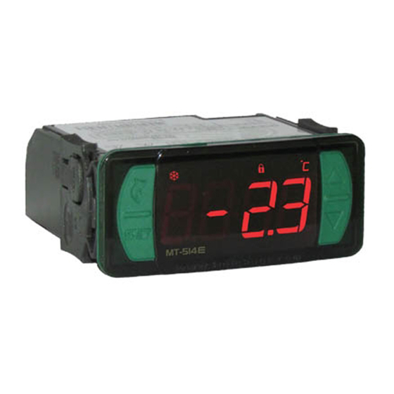
1. DESCRIPTION
e
The MT-514
is a temperature controller for cooling or heating applications. It has an internal
audible alarm (buzzer) and an output for alarm control that can also be configured for electric defrost,
hot gas defrost, fan or as a second compressor that will act in parallel with the main one. The minimum
and maximum temperature record is displayed at the touch of a single key ; (Flatec). Another
available feature is the shutdown of control functions, making it possible for the MT-514
operate only as a temperature indicator. And through an intelligent function blocking system, it prevents
unauthorized persons from changing the control parameters.
Product is compliant with UL Inc. (United States and Canada).
2. APPLICATION
• Vaccine refrigerators
• Refrigerated counters
• Freezer rooms
• Hot counters
3. TECHNICAL SPECIFICATIONS
Power supply
Control temperature
Operating temperature
Load current (outputs)
Operating humidity
Dimensions (WxHxD)
Dimensions of the clipping for fixing
of the instrument
(*) This instrument measures and controls temperatures of up to 200°C/392°F, using the silicone sensor cable SB59
(sold separately).
Note: The sensor cable lenght can be increased by the user up to 200 meters using PP 2 x 24 AWG cable.
4. INDICATIONS AND KEYS
Defrost indication LED
Heating indication LED
Cooling indication LED
Quick Access
Menu Key (Flatec)
Set key
e
MT-514
*Blinking led (when [F26] = 7): Indicates that OUT1 has been activated and the compressor delay is ocurring before
trigger OUT2
5.
INSTALLATION - ASSEMBLING AND ELECTRICAL CONNECTIONS
MT-514
DIGITAL CONTROLLER FOR HEATING OR COOLING
WITH DEFROST AND CONFIGURABLE
ALARM OUTPUT
Audible
Defrost
Function
Control functions
Alarm
blocking
shutdown
MT-514 E: 115 or 230 Vac ±10%(50/60 Hz)
MT-514 EL: 12 or 24 Vac/dc +10%
-50 to 105ºC (-58 to 221°F)*
0 to 50 ºC / 32 to 122°F
OUT1: 16(12)A 250Vac 2HP
OUT2: 10A / 240Vac 1/4HP
10 to 90%RH (without condensation)
76 x 34 x 77 mm
71 ± 0,5 x 29 ± 0,5 mm (see item 5)
Alarm indication LED
Functions lock indication LED
Temperature unit indication LED
71
± 0,5
mm
Dimension of the clipping
for fixing of the
instrument in panel
Panel
(Side View)
Panel (Front View)
e
IP 65
FRONT
Serial
Protection
Programming
level
ATTENTION
FOR INSTALLATIONS WHERE A SEALING IS REQUIRED
TO AVOID LIQUID CONTACT, THE CUT FOR THE
CONTROLLER MUST BE OF 70,5X29mm MAXIMUM. THE
SIDE LOCKS MUST BE FIXED SO IT PRESSES THE
RUBBER SEALING AVOIDING INFILTRATION BETWEEN
THE CUT AND THE CONTROLLER.
Connection
115 Vac
Connection
230 Vac
Connection
12 Vac/dc
e
to
Connection
24 Vac/dc
6. OPERATIONS
6.1. Quick Access Menu Map
To access or browse in the quick access menu, use the
being displayed by the controller. Each touch displays the next function of the list; for confirming, use
/
the
key (quick touch). For further details, refer to chapter 6.3.
DEFROST (ON/OFF)
;
e
MT-514
FUNCTIONS LOCKDOWN
;
e
MT-514
CONTROL FUNCTIONS
(ON/OFF)
;
e
MT-514
Increase key
ADJUSTING DESIRED
TEMPERATURE
(SETPOINT)
Decrease key
;
e
MT-514
6.2. Quick access keys map
When controller is on temperature display mode, the following keys can be used as a shortcut for the
following functions:
/
Hold down for 2 seconds: setpoint adjustment.
<
Quick touch: displayof current process and sensor temperature when
[F41] = 1 or 2.
<
Hold down for 2 seconds: inhibit audible alarm (buzzer).
<
Quick touch: maximum and minimum temperature display.
;
Pressed for 5 seconds: turn on/turn off the control functions.
e
e
M T- 51 4
M T- 51 4
IMPORTANT
THE USE OF APPROPRIATE TOOLS IS ESSENTIAL TO AVOID
DAMAGE IN THE CONNECTION AT INSTRUMENT TERMINALS:
SCREWDRIVER SLOT 3/32''(2.4mm) FOR ADJUSTMENTS IN THE
SIGNAL TERMINALS;
SCREWDRIVER PHILLIPS #1 FOR ADJUSTMENTS IN THE POWER
TERMINALS;
POWER
5 6 7 8
NC
SUPPLY
NO
9
10 11 12 13 14 15 16 17
1
2 3 4
D1
SENSOR
POWER
5 6 7 8
NC
SUPPLY
NO
9
10 11 12 13 14 15 16 17
1
2 3 4
D1
SENSOR
POWER
5 6 7 8
NC
SUPPLY
NO
9
10 11 12 13 14 15 16 17
1
2 3 4
D1
SENSOR
12 Vac/dc
POWER
5 6 7 8
NC
SUPPLY
NO
9
10 11 12 13 14 15 16 17
1
2 3 4
D1
SENSOR
24 Vac/dc
;
key (quick touch) while the temperature is
MIN. AND MAX.
TEMPERATURE RECORD
;
e
MT-514
evolution
COMPONENT
E251415
REFR
HEAT
115 Vac
Loads supply
REFR
HEAT
230 Vac
Loads supply
REFR
HEAT
Loads supply
REFR
HEAT
Loads supply
EXIT FUNCTION
;
e
MT-514
FUNCTION SELECTION
;
e
MT-514
VISUALIZATION OF
PROCESSES
;
e
MT-514
ERASE MIN. AND MAX.
VALUES
;
e
MT-514
Advertisement

Related Manuals for Full Gauge Controls Evolution MT-514 E


Summary of Contents for Full Gauge Controls Evolution MT-514 E
- Page 1 Connection 5 6 7 8 HEAT SUPPLY DUE TO YOUR CONSTANT EVOLUTION, THE FULL GAUGE CONTROLS RESERVES THE RIGHT TO 230 Vac 10 11 12 13 14 15 16 17 2 3 4 CHANGE THE INFORMATION CONTAINED IN THIS MANUAL AT ANY TIME WITHOUT NOTICE.
- Page 2 < 6.3.6. Minimum and Maximum Temperature Record Hold down for 4 seconds: carries out manual defrost. < Pressing down the key or also via the quick access menu (see chapter 6), will cause the message Quick touch: enters quick access menu. [rE9,] to be displayed, then the minimum and maximum temperatures recorded.
-
Page 3: Description Of Parameters
6.5.1. Description of parameters F17 - Initial status when energizing the instrument: It allows defrosting when controller is energized such as, for example, upon resuming of electric power F01- Access code 123 (one hundred and twenty-three): (in the event of power outage). This is required when intending to change the configuration parameters. - Page 4 Parallalel connection Serial connection [OFF,] Control functions off. 5 6 7 8 5 6 7 8 2 3 4 2 3 4 [eCAL] Contact Full Gauge Controls. [pppp] SENSOR SENSOR Reconfigure the values of the functions. Door contact Door contact...
-
Page 5: Environmental Information
Extension Frame - The product is violated or repaired by any person not a member of the technical team of The Full Gauge Controls extension frame allows the installation of Evolution / Ri line with measures Full Gauge Controls; 76x34x77 mm (dimensions of the clipping for fixing in the extension frame is 71x29mm) in varied - Damage has been caused by a fall, blow and/or impact, infiltration of water, overload situations, since it eliminates precision cut to embed the instrument.