
Related Manuals for Qorvo MDEK1001


Summary of Contents for Qorvo MDEK1001
- Page 1 MDEK1001 Kit User Manual Module Development & Evaluation Kit for the DWM1001 Version 1.3 This document is subject to change without notice © Decawave 2017 -MDEK1001-Kit-User-Manual-1.3...
-
Page 2: Table Of Contents
MDEK1001 Kit User Manual TABLE OF CONTENTS INTRODUCTION ........................8 ........................... 8 VERVIEW DWM1000 RTLS ....................8 MODULE AND MDEK1001 ....................8 EATURES OF THE ........................... 8 NALYTICS ........................9 NFORMATION KIT CONTENTS ........................10 MDEK1001 B ....................10 UPPLIED IN THE ........................ - Page 3 MDEK1001 Kit User Manual DOCUMENT HISTORY ......................41 ........................41 EVISION ISTORY FURTHER INFORMATION ....................42 LIST OF TABLES 1: K ..........................10 ABLE ONTENTS 2: A ..............11 ABLE REQUIRED OR USEFUL NOT PROVIDED IN THE BOX 3: A ..................
- Page 4 User bears all responsibility for obtaining such approval. If the user has obtained the MDEK1001 for any purpose other than those listed above the user should return the MDEK1001 to the supplier immediately.
- Page 5 MDEK1001 Kit User Manual DISCLAIMER This Disclaimer applies to the software provided by Decawave Ltd. (“Decawave”) in support of its DWM1001 module product (“Module”) all as set out at clause 3 herein (“Decawave Software”). Decawave Software is provided in two ways as follows: - pre-loaded onto the Module at time of manufacture by Decawave (“Firmware”);...
- Page 6 MDEK1001 Kit User Manual The Decawave DRTLS Manager application uses open source software which is provided as source code in the Software Bundle. This open source software is provided under the terms of the Apache Licence v2.0 which may be found at http://www.apache.org/licenses/LICENSE-2.0;...
- Page 7 MDEK1001 Kit User Manual designing your systems and products. THE DECISION TO USE DECAWAVE SOFTWARE IN WHOLE OR IN PART IN YOUR SYSTEMS AND PRODUCTS RESTS ENTIRELY WITH YOU AND DECAWAVE ACCEPTS NO LIABILTY WHATSOEVER FOR SUCH DECISION. DECAWAVE SOFTWARE IS PROVIDED "AS IS". DECAWAVE MAKES NO...
-
Page 8: Introduction
MDEK1001 Kit User Manual NTRODUCTION 1.1 Overview The MDEK1001 is a development and evaluation kit that allows the user to evaluate the Decawave’s DWM1001 module. MDEK1001 stands for Module Development & Evaluation Kit for the Decawave DWM1001. 1.2 The DWM1000 module and RTLS The DWM1001 is a module product natively supporting the Positioning and Networking Stack (PANS) firmware. -
Page 9: More Information
MDEK1001 Kit User Manual 1.5 More Information More information about the MDEK1001, the DWM1001-DEV Development Board, the DWM1001 module, PANS and the DW1000 IC can be found on the Decawave website. © Decawave Ltd 2017 MDEK1001 Kit User Manual Version 1.3... -
Page 10: Kit Contents
MDEK1001 Kit User Manual ONTENTS 2.1 Supplied in the MDEK1001 Box The following items are included in the box. Table 1: Kit Contents Description Quantity Image RTLS units Containing DWM1001-DEV Development Boards 1.0 m USB Cable Adhesive Pads Right-Angled USB Connectors... -
Page 11: Items Not Included
MDEK1001 Kit User Manual 2.2 Items Not Included Other items, not included in the box are listed below. Table 2: Also, required or useful, not provided in the box Description Quantity Image Notes Android Tablet or Smartphone Required (to run the... -
Page 12: Available From The Decawave Website
MDEK1001 Kit User Manual Description Quantity Image Notes Power Adaptor to USB PC to USB (USB micro type B) 2.3 Available from the Decawave Website Table 3: Available on the Decawave Website Description Details Decawave DRTLS Manager: Android application file (.apk) for tablet/smartphone application configuration &... -
Page 13: The Dwm1001-Dev Development Board
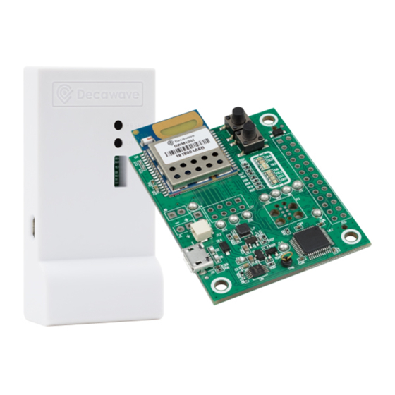
MDEK1001 Kit User Manual DWM1001-DEV D EVELOPMENT OARD The image below shows the key features of a DWM1001-DEV development board: • Decawave DWM1001 module soldered in place • Li-Po/Li-ion battery charging circuit (Battery charger not mounted on boards shipped after November 2021) •... - Page 14 MDEK1001 Kit User Manual NOTE: Details of the functions of these LEDs are given in the DWM1001-DEV Datasheet. D9, D12, D11 and D10 LED functionalities are valid when using PANS firmware only. © Decawave Ltd 2017 MDEK1001 Kit User Manual Version 1.3...
-
Page 15: System Setup & Preparation
MDEK1001 Kit User Manual & P YSTEM ETUP REPARATION 4.1 Prepare the Anchors • Select some of the RTLS units as anchors – 3 is the minimum for RTLS but at least 4 is recommended for accuracy • Mount the anchors on the wall or on tripods (as shown in the figure below) o Mounting them high will give better performance (due to Line-of-Sight) •... -
Page 16: System Configuration Examples
MDEK1001 Kit User Manual YSTEM ONFIGURATION XAMPLES 5.1 1 Anchor + 1 Tag This configuration can be used for a simple proximity demonstration: • Configure 1 RTLS unit as an initiator anchor by using the tablet (section 6) or PC (section 7) •... -
Page 17: Anchors + 8 Tags
MDEK1001 Kit User Manual 5.2 4 Anchors + 8 Tags This configuration is the minimum recommended anchor configuration for an RTLS system: • Configure 4 RTLS units as anchors • Configure 8 RTLS units as tags • The tablet shows the tablet positions of up to 2 tags Figure 5: System Configuration Option: 4 Anchors, 8 Tags •... -
Page 18: Anchors + 1 Tag
MDEK1001 Kit User Manual 5.3 11 Anchors + 1 Tag This configuration uses as many anchors as possible (in this kit) to show how the anchors scale and a tag can dynamically select the best anchors, as it traverses though the area covered by the anchors. -
Page 19: Anchors + 7 Tags + 1 Listener
MDEK1001 Kit User Manual 5.4 4 Anchors + 7 Tags + 1 Listener By configuring one of the devices as a listener device, the data can be captured to a PC directly. • Set one of the RTLS units (anchor) into PASSIVE mode. In this mode the UWB is enabled but it is not participating in the network •... -
Page 20: Anchors + 2 Tags + 2 Gateways
Access to location and configuration data through an MQTT broker • Downlink/Uplink IoT data from/to gateway to/from network nodes Figure 9: Deployment of gateway with MDEK1001: 8 anchors, 2 tags, 2 gateways For detailed information regarding the deployment of gateway within a PANS network, refer to the DWM1001_Gateway_Quick_Deployment_Guide [8]. -
Page 21: Drtls Manager Usage Guide
MDEK1001 Kit User Manual 6 DRTLS M ANAGER SAGE UIDE Follow the steps below to get the DWM1001 Two-Way-Ranging Real Time Location System (DRTLS) up-and-running. 6.1 Open the Android Application • Open the Decawave DRTLS Manager • If no networks have been previously saved the application will open on the home screen •... -
Page 22: Start Device Discovery
MDEK1001 Kit User Manual 6.2 Start Device Discovery • Tap “Start Device Discovery” • The application will automatically discover all devices that are in range and powered Figure 11: Device Discovery Screen • Devices will be grouped into o ‘ ETWORKS’... -
Page 23: Figure 12: Device Discovery Screen - Select Multiple Devices
MDEK1001 Kit User Manual Figure 12: Device Discovery Screen – Select Multiple Devices © Decawave Ltd 2017 MDEK1001 Kit User Manual Version 1.3 Page 23... -
Page 24: Create A Network
MDEK1001 Kit User Manual 6.3 Create a Network • Name the Network e.g. “Network 1” and • Tap ‘Save’ Figure 13: Name Network Screen • The new network will appear in the ‘ ETWORKS’ group and the devices will move from the ‘U ASSIG ED DEVICES’... -
Page 25: Network Device Configuration
MDEK1001 Kit User Manual Figure 14: Networks& Devices List 6.4 Network Device Configuration 6.4.1 ‘Networks & Devices page’ • Tap a network to see the list of devices in that network Figure 15: Network Details Screen Each device in the list shows information about that device. -
Page 26: Remove A Device From A Network
MDEK1001 Kit User Manual Bluetooth Signal strength icon Edit icon – goes to the ‘Details’ screen for that device • Tag icons: Location icon - jumps to the grid screen and zooms to this tag o Ranging Display icons: ▪... -
Page 27: Device 'Details' Page
MDEK1001 Kit User Manual 6.4.3 Device ‘Details’ page The user can edit the parameters of this device. Note after changing a parameter, the new setting needs to be saved by tapping in the upper-right of the screen. Figure 18: Device Details Screen – Anchor & Tag The following parameters are displayed: •... -
Page 28: Tip: Label Your Devices
MDEK1001 Kit User Manual o INITIATOR Configure this anchor as an initiator. At least one of the anchors must be an initiator in the network. The initiator will start and control the network o POSITION Position: The x,y,z co-ordinate of the anchor in the grid. -
Page 29: Position The Anchors
MDEK1001 Kit User Manual 6.4.5 Position the Anchors 6.4.5.1 By using the Auto-Positioning Feature (for up to 4 anchors) Note 1: The Auto-Positioning function is a quick setup feature to automatically determine the anchor locations. Note that this feature may result in a small error in anchor location, making reported tag locations less accurate. -
Page 30: Show Location
MDEK1001 Kit User Manual Figure 20: Auto-Positioning: Anchor Positioning Rules 6.4.5.2 By Manual Positioning • In turn, open each anchor’s device configuration screen • Enter the x, y, z co-ordinates of the anchors 6.5 Show Location • Ranging starts automatically once devices have been added to the network and the... -
Page 31: Figure 21: Grid Screen - Anchor Placement & Tag Tracking
MDEK1001 Kit User Manual Figure 21: Grid Screen – Anchor Placement & Tag Tracking In networks where there are more than 4 anchors, the anchor selection can be viewed on the grid by moving the tag from one position to another. - Page 32 MDEK1001 Kit User Manual In the upper-right pulldown menu – there are 2 options: • Floor plan • Show grid © Decawave Ltd 2017 MDEK1001 Kit User Manual Version 1.3 Page 32...
-
Page 33: Side Menu Options
MDEK1001 Kit User Manual 6.6 Side Menu Options Tap the menu icon on the top left of the home screen. This will display the following options: o A list of previously saved networks o “Networks & Devices” o “Position log”... -
Page 34: Settings
MDEK1001 Kit User Manual Figure 24: Decawave DRTLS Manager Position Log 6.6.2 Settings The following settings are available • “Imperial” yards or “Metric” metres Units • Version Application version • About General information © Decawave Ltd 2017 MDEK1001 Kit User Manual Version 1.3... -
Page 35: Figure 25: Decawave Drtls Manager Settings Screen
MDEK1001 Kit User Manual Figure 25: Decawave DRTLS Manager Settings Screen © Decawave Ltd 2017 MDEK1001 Kit User Manual Version 1.3 Page 35... -
Page 36: Logging Data Via The Usb Port
MDEK1001 Kit User Manual USB P OGGING ATA VIA THE Tag location data can be logged using a USB connection instead of using the Android application. Note also that the PC terminal can be used to configure the anchors and tags – the Android application is not necessarily needed. -
Page 37: Example Output
MDEK1001 Kit User Manual Next press the PC Enter key two times and the prompt below appears: Enter the command ‘nmt’ and press the return key twice which sets the tag into Active mode Enter ‘les’ to display the location estimates of the tag 7.2 Example Output... - Page 38 MDEK1001 Kit User Manual ** Command group: Base ** ?: this help help: this help quit: quit ** Command group: GPIO ** gc: GPIO clear gg: GPIO get gs: GPIO set gt: GPIO toggle ** Command group: SYS ** f: Show free memory on the heap...
- Page 39 MDEK1001 Kit User Manual ** Command group: API ** tlv: Send TLV frame aurs: Set upd rate aurg: Get upd rate apg: Get pos aps: Set pos acas: Set anchor config acts: Set tag config aks: Set encryption key akc: Clear encryption key...
-
Page 40: References
MDEK1001 Kit User Manual EFERENCES 8.1 Listing Reference is made to the following documents in the course of this document: Table 4: Table of References Author Date Version Title Decawave Current MDEK1001 Quick Start Guide Decawave Current DWM1001-DEV Product Brief... -
Page 41: Document History
MDEK1001 Kit User Manual OCUMENT ISTORY 9.1 Revision History Table 5: Document History Revision Date Description 13 Nov 2021 Battery charger not mounted on boards shipped after November 2021 29 March 2019 Update to Release 2 Update with new logo... -
Page 42: Further Information
MDEK1001 Kit User Manual 10 FURTHER INFORMATION Decawave develops semiconductors solutions, software, modules, reference designs - that enable real-time, ultra-accurate, ultra-reliable local area micro-location services. Decawave’s technology enables an entirely new class of easy to implement, highly secure, intelligent location functionality and services for IoT and smart consumer products and applications.
Need help?
Do you have a question about the MDEK1001 and is the answer not in the manual?
Questions and answers