
Related Manuals for Hog Technologies PAINT HOG


Summary of Contents for Hog Technologies PAINT HOG
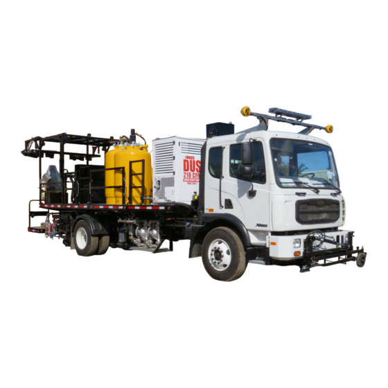
- Page 1 PAINT HOG Operation Manual SE Slater Street Stuart, FL 34997 1-877-HOG-ROAD (001) (772) 223-7393 WWW. STRIPEHOGSUPPORT.COM...
-
Page 3: Copyright/General Warning
Copyright/General Warning COPYRIGHT Hog Technologies maintains and holds all rights and privileges to the in- formation contained in the manual. The contents herein cannot be shared or reproduced in any way or by any method without prior express writ- ten consent by an authorized representative. Copies of this manual are available by calling (772) 223-7393. - Page 4 STOP TO AVOID SERIOUS INJURY, MAKE SURE TO COMPLETELY READ THIS MANUAL AND FOLLOW ALL SAFETY PRECAUTIONS LISTED IN THE MANUAL AND ON COMPONENT LABELS BEFORE OPERATING THIS EQUIPMENT.
-
Page 5: Table Of Contents
1.5 Fire Hazard ........................13 1.6 Fueling Fire Hazard .....................14 1.7 Fall Hazard .........................14 Section 2: Paint Hog Systems 2.1 Paint Hog System Introduction ..................15 2.2 Truck Chassis ......................16 2.3 Paint Deck .........................17 2.4 Auxiliary Engine/Air Compressor ...................18 2.5 Compressed Air Supply System ..................20 2.6 Hydraulic System ......................23... - Page 6 4.7 Water Heater & Burner Maintenance (Optional) ...............72 4.8 Hydraulic System Maintenance ..................74 4.9 Compressed Air System ....................76 4.10 Hand Gun, Reel & Hoses .....................78 4.11 Maintenance Matrix ....................79 Appendix 1: ....................81 Pre-Operation Check List Appendix 2: .....................83 Hog Technologies Support...
-
Page 7: Welcome
Hog Technologies is excited to welcome you and your crew to the Paint Hog Operators’ Team. Together we embrace the challenge of constantly developing our equipment, knowledge and skills so that our highways will be safer for all who rely on them and our pavement marking will last longer for those who pay for them. -
Page 8: Hog Technologies Limited Warranty
Hog Technologies warrants its components to be free from defects in material and workmanship while under normal use and service. Hog Technologies will, at its option, either repair or replace free of charge any such part that appears to us to be defective in material or workmanship during the warranty period. -
Page 9: Safety Warnings & Instructions
ENVIRONMENT OR CAUSE THE EQUIPMENT TO OPERATE IMPROPERLY. Every precaution has been taken by Hog Technologies to reduce the risks associated with possible injury and damage from electrical faults, high temperature antifreeze, paint or components, hydraulic components or mechanical failure. However, your own precaution and good maintenance procedures are necessary in order to maintain a safe working environment. - Page 10 NOTES...
-
Page 11: Safety Information
OSHA standards. Read this manual and all other equipment opera- tion manuals and instructions prior to using any Hog Technologies product. Contact Hog Technolo- OSHA’s Permissible Noise Exposure gies (877-HOG ROAD) should any questions arise. -
Page 12: Hot Fluids & Components Hazard
The following precautions apply whenever If you have questions about the equipment on a vehicle equipped with an optional paint your Paint Hog, please contact the Customer sup- heating system is operating: port Department at (877) HOG ROAD or (001) •... -
Page 13: Electrical System Hazards
Section 1 - Safety Information • Always depressurize the hydraulic system 1.3 Electrical System Hazards before removing any hydraulic components, The electrical system on your vehicle is powered hoses or fittings. Failure to do so could result by a high amperage 12 volt DC electrical system. in serious injury or death. -
Page 14: Fueling Fire Hazard
Section 1 - Safety Information 1.7 Fall Hazard DANGER The deck and rear platform are high off the ground and personnel can be severely injured if they fall RESTRICTED HEATER EXHAUST PIPES WILL CAUSE from deck or platform. To reduce the possibility EXCESSIVE BURNER AND EXHAUST TEMPERATURES THAT for a fall, the following precautions apply: COULD DAMAGE COMPONENTS OR RESULT IN A FIRE OR... -
Page 15: Paint Hog Systems
Section 2: Paint Hog Systems Paint Hog 2.1 Paint Hog System Introduction cate with the spray gun operator (switchman) at The pavement marking system is mounted to the the rear control station. truck chassis. It is powered by the air compressor auxiliary engine mounted front of the deck. -
Page 16: Truck Chassis
Section 2 - Paint Hog Systems 2.2 Truck Chassis The paint system components are mounted on a heavy duty truck chassis. Other than the truck batteries supplying DC electrical power to 12 volt system, the system is completely isolated from truck. -
Page 17: Paint Deck
Section 2 - Paint Hog Systems Paint Deck 2.3 Paint Deck WARNING The paint deck is located between the cab and rear control station. The deck accommodates the paint ANYONE ON THE DECK WHILE THE TRUCK IS MOVING tanks, bead tank, water tank, the auxiliary engine/... -
Page 18: Auxiliary Engine/Air Compressor
Section 2 - Paint Hog Systems 2.4 Auxiliary Engine/Air Compressor General The following is an overview of the features and operation of the auxiliary engine/air compressor for general information purposes. The manufac- turer of the unit supplies an operation and main- tenance manual. - Page 19 Section 2 - Paint Hog Systems Auxiliary Engine/Compressor Control Panel Unloader Valve Emergency Stop Switch Bypass Switch Hydraulic Pressure OFF-ON-Run Switch Engine/Compressor Controls CAUTION The engine controls in the panel include the fol- lowing: NEVER USE THE EMERGENCY STOP SWITCH TO SHUTDOWN THE AIR COMPRESSOR ENGINE.
-
Page 20: Compressed Air Supply System
Section 2 - Paint Hog Systems Gauges in the panel and on the sound shield moni- tor critical engine systems, compressed air system pressure and hours of operation. Refer to the en- gine and compressor operation and maintenance manual for additional information on gauges and operating parameters for the compressor. - Page 21 Section 2 - Paint Hog Systems Unfiltered Air Dried and cooled, high volume air is delivered to the spray gun atomizing nozzles, the high volume broom nozzles that sweep the pavement in front of the guns, the bead tank vacuum venturi and paint transfer pumps.
- Page 22 Section 2 - Paint Hog Systems Filtered Air Unfiltered dried and cooled air is treated again by three filter/driers mounted on the passenger side of the chassis below the rear deck. The filter bowls are equipped with drain valve that automatically drain accumulated water from the bowl.
-
Page 23: Hydraulic System
Section 2 - Paint Hog Systems 2.6 Hydraulic System Overview The auxiliary engine that powers the air compres- sor also powers the hydraulic pump. The system includes a hydraulic manifold, reservoir tank and a low pressure filter. An oil cooler with a constant on fan cools the hydraulic fluid during operation. - Page 24 All hydraulic circuits and actuators require special procedures for bleeding air from the system after servicing components or replacing hoses. Contact Hog Technologies if you need assistance in bleeding the air from the hydraulic system. Mixer Motor Speed Control Valve...
-
Page 25: Paint Tanks & Delivery System
Section 2 - Paint Hog Systems 2.7 Paint Tanks & Delivery System Overview Two paint tanks, white and yellow are standard equipment. A black tank is an available option. Each tank is pressurized with filtered and dried air by the filtered air system. Typical tank pressure is around 40 PSI (2.76 Bar). -
Page 26: Paint Tank Fill System
Section 2 - Paint Hog Systems WARNING NEVER ATTEMPT TO REMOVE THE SIGHT CAP WHILE THE PAINT TANK IS PRESSURIZED. PRESSURE IN THE TANK WILL MAKE THE CAP EXTREMELY HARD TO REMOVE AND WILL BLOW THE CAP FROM THE TANK UNEXPECTEDLY DURING REMOVAL. -
Page 27: Pressurized Flush Water System
Section 2 - Paint Hog Systems The pneumatic pumps are powered by unfiltered compressed air at manifold pressure that is acti- vated by a manual valve at the pump. Other valves near the pump inject and discharge freshwater to flush out the pump and lines when filling opera- tions are completed. -
Page 28: Paint Heater System (Optional)
Section 2 - Paint Hog Systems Typical Paint Heater & Lower Reservoir Typical Paint Heat Exchangers 2.10 Paint Heater System (Optional) Overview A diesel fuel fired heater, heat exchangers and antifreeze circulation system heats the paint dur- ing cold weather operations. A circulation pump... - Page 29 Section 2 - Paint Hog Systems Antifreeze Expansion Tank The paint heating system antifreeze reservoir is equipped with an expansion tank mounted on the top of the air compressor. As antifreeze is heated, it expands. The expansion tank allows the expanded antifreeze to accumulate so it doesn’t...
-
Page 30: Bead Tank & Delivery System
Section 2 - Paint Hog Systems 2.11 Bead Tank & Delivery System The bead tank is mounted on the deck near the paint tanks. Dual bead tanks is an available option. Each tank is pressurized by the filtered air system and equipped with three sight gauges to monitor bead level. - Page 31 Section 2 - Paint Hog Systems Bead Tank Fill Valve & Cap Note: Trucks with the dual bead tank option will have two bead fill valves. DANGER NEVER OPEN THE FILL VALVE AND REMOVE THE CAP WHILE THE BEAD TANK IS PRESSURIZED. PRESSURE IN THE TANK...
- Page 32 Section 2 - Paint Hog Systems Bead Delivery System The bead delivery system includes tubing, hoses, manifolds and valves that channel the beads from the tank to the bead guns. When the tank is pressurized and the supply valve is turned on, the beads will flow through the tubing and hoses to the manifolds.
-
Page 33: Spray Gun Carriages
Section 2 - Paint Hog Systems 2.12 Spray Gun Carriages There is a spray gun carriage mounted below each side of the rear control station. Each carriage is equipped with paint spray guns, bead guns, and pneumatically activated nozzles. The carriages are always retracted and raised for travel and lowered only when applying paint. -
Page 34: Rear Control Station
Section 2 - Paint Hog Systems Rear Control Station With Optional Paint Heater System 2.13 Rear Control Station The rear control station is located on the rear of the deck. It is equipped with a large control con- sole with switches and pressure regulators that control most of the paint deck components. - Page 35 Section 2 - Paint Hog Systems Hand Gun & Hose Reel (Optional) A hand gun and hose reel typically used for paint- ing stencils is an available option. Two manual valves near the real are used to select either white or yellow pant to be delivered to the spray gun.
-
Page 36: Volt Electrical System
Section 2 - Paint Hog Systems Typical Rear Control Console Switch Panel Typical Cab Switch Panel With Optional Paint Heater System 2.14 12 Volt Electrical System Overview The truck 12 volt electrical system provides elec- trical power for the switches, solenoids and other electrical components in the paint system. - Page 37 Section 2 - Paint Hog Systems Main Circuit Breakers The heavy duty main circuit breakers are con- nected directly to battery through relays acti- vated when the ignition switch and cab control panel POWER MASTER switch are ON. They supply electrical power directly to front and rear control panels.
- Page 38 Section 2 - Paint Hog Systems Rear Control Console Switch Panel In-Line Fuses Cab Main Switch Panel Fuses Accessory Circuit Protection ATC blade type fuses in fuse panels or in-line fuse holders located inside the front and rear control panels protect most circuits activated by the switches.
-
Page 39: Cab Control Switches & Panels
Section 2 - Paint Hog Systems Cab Main Control Switch Panel Note: The switch panel shown is typical of the panels used in most trucks. The panel in your truck may be different, depending on the options selected. 2.15 Cab Control Switches & Panels... - Page 40 Section 2 - Paint Hog Systems desired position. When the top of the switch is released, it returns to the center (HOLD) position and locks the arm. Press and hold the bottom of the switch to lower the arm. The arm will lower to the pavement and FLOAT mode will be engaged.
-
Page 41: Cameras & Video System (Optional)
Section 2 - Paint Hog Systems Dual Truck Controls (Optional) Trucks can be equipped with dual steering and controls. Refer to the truck operation manual for information on the dual control system. Right & Left Carriage/Spray Gun Control Panel (Optional) - Page 42 Section 2 - Paint Hog Systems Check the plunger frequently to make sure the cup remains securely attached. If the red line begins to show, pump the plunger to increase vacuum. Remove the monitor and clean the suction cup and windshield if the red line becomes exposed frequently.
-
Page 43: Rear Control Station Switches And Panels
Section 2 - Paint Hog Systems Rear Control Station Note: Some components, switches and regulators shown are optional. Your truck may be different, depending on the options selected. two bolts. It can be opened to access the fuses 2.17 Rear Control Station... - Page 44 Section 2 - Paint Hog Systems Typical Rear Control Panel Switches Typical Rear Control Panel Switches With Optional Paint Heater System Without Optional Paint Heater System CARRIAGE STROBE LEFT RIGHT STEERING Activates the strobe lights on the driver side spray Releases the lock that prevents the right carriage gun carriage.
- Page 45 Section 2 - Paint Hog Systems E-STOP Shuts down the power to all paint system compo- nents and stops all paint system operations. Once pressed, this button remains in the STOP position until it is reset by the operator. Paint Heating System Switches (Optional) The following switches will be in the panel if your truck is equipped with the paint heater option.
- Page 46 Section 2 - Paint Hog Systems Rear Panel Pressure Regulators & Pressure Gauges Lower Panel Controls And Gauges GUN 2 ATOMIZER A pressure gauge and regulator that monitors Pressure regulators and gauges that control the and sets atomizer pressure for spray gun 2 on operation of pneumatically activated components the left carriage.
- Page 47 Section 2 - Paint Hog Systems GUN 1 ATOMIZER A pressure gauge and regulator that monitors and sets atomizer pressure for spray gun 1 on the right carriage. YELLOW PAINT A pressure gauge and regulator that monitors and sets air pressure in the yellow paint tank.
- Page 48 Section 2 - Paint Hog Systems WARNING IN SOME SITUATIONS, IT IS POSSIBLE FOR THE HYDRAULIC CYLINDERS THAT MOVE EACH CARRIAGE IN OR OUT TO GRADUALLY DRIFT OUT WHILE TRAVELING IF EACH STEERING SWITCH IS NOT TURNED OFF WHEN THE TRUCK IS IN TRAVEL MODE.
-
Page 49: Access Panels, Ladders & Tool Boxes
Section 2 - Paint Hog Systems 2.18 Access Panels, Ladders & Tool Boxes Ladders Ladders on each side of the deck provide access to the tanks, air compressor and other components located on the deck. Each ladder is hinged and has a spring loaded safety pin that locks the ladder in the stored position. - Page 50 NOTES...
-
Page 51: Operation
The startup and shutdown procedures described in 3.1 Start Up/Shutdown Introduction this section are for a typical system. This informa- Before operating the Paint Hog, check the fluid tion is provided as a general guide and overview levels in the truck engine, transmission, air com- of the process for educational purposes. -
Page 52: Pre-Operation Inspection
Section 3 - Operation 13. Check bead level in tank. Fill if necessary. 3.2 Pre-Operation Inspection Refer to filling the bead tank. The pre-operation Inspection in this section and the Pre-Op Check List in Appendix 4 is provided as a guideline. Additional items should be added NOTICE: to the checklist as determined by company policy, IF YOU NEED TO FILL THE PAINT AND BEAD TANKS, FOLLOW... -
Page 53: Starting & Stopping The Air Compressor
Section 3 - Operation Air Compressor Controls & Gauges Unloader Valve Emergency Stop Switch Bypass Switch Compressed Air System Supply Valves OFF-ON-Run Switch Exhaust Valve Stopping the compressor 3.3 Starting & Stopping 1. Set the UNLOADER valve to Unload. the Air Compressor Starting the Compressor 2. -
Page 54: Filling The Water Tank
Section 3 - Operation 3.4 Filling The Water Tank 1. Make sure the air compressor is running and system pressure has stabilized. 2. Close air supply valve on top of the water tank. 3. Open the exhaust valve to bleed off tank pressure. - Page 55 Section 3 - Operation CAUTION DO NOT OPEN THE AIR PRESSURE VALVE TOO MUCH. THE VALVE NEEDS TO BE OPEN ONLY ENOUGH FOR THE PUMP TO FUNCTION. BARELY OPEN WILL BE SUFFICIENT. IF IT IS OPENED TO FAR, EXCESSIVE AIR PRESSURE CAN QUICKLY DAMAGE THE PUMP.
-
Page 56: Filling Bead Tank
Section 3 - Operation 3.6 Filling Bead tank 1. Make sure the air compressor is running and system pressure has stabilized. 2. Close air supply valve on top of tank. 3. Open the exhaust valve to bleed off tank pressure. 4. -
Page 57: Changing Spray Gun Paint Color
Section 3 - Operation 3.7 Changing Spray Gun Paint Color The capability to paint extra wide paint lines is an available option. The paint supply lines going to the guns for extra wide strips are designed to be switched to different color paint. The procedure to change the paint color to the carriage is as follows. -
Page 58: Starting Paint Operations
Section 3 - Operation Shutting Down The Paint Heating System The paint system must be shutdown if spray opera- tions stop for more than 10 minutes or immediately after spray operations stop for the current shift. CAUTION DO NOT ALLOW HEATER SYSTEM TO OPERATE FOR MORE THAN 10 MINUTES AFTER PAINT OPERATIONS STOP. -
Page 59: Routine Paint System Shutdown
Section 3 - Operation CAUTION DO NOT ALLOW HEATER SYSTEM TO OPERATE FOR MORE THAN 10 MINUTES AFTER PAINT OPERATIONS STOP. HEAT SYSTEM WILL OVERHEAT WITHOUT PAINT FLOWING. THIS WILL RESULT IN DAMAGE TO THE PAINT AND HEATING SYSTEMS. 3.10 Routine Paint System Shutdown 1. -
Page 60: Hand Spray Gun Operation
Section 3 - Operation 3.11 Hand Spray Gun Operation Deploying the hand spray gun: 1. Activate the paint system. Refer to section 3.9 Starting Paint Operations. 2. If necessary, install the nozzle shroud on the spray gun. 3. Pull the spray gun and hoses out from the reel. 4. -
Page 61: Emergency Shutdown
Section 3 - Operation 3.12 Emergency Shutdown WARNING IF AN EMERGENCY SITUATION INVOLVING THE POTENTIAL FOR PERSONAL INJURY AND/OR EQUIPMENT DAMAGE OCCURS, THE OPERATOR OR SWITCHMAN SHOULD AL- WAYS SELECT THE EMERGENCY SHUTDOWN PROCEDURE. THIS PROVIDES IMMEDIATE SHUTDOWN OF THE PAINT SYSTEMS TO REDUCE THE POSSIBILITY OF INJURY AND DAMAGE TO EQUIPMENT. - Page 62 Section 3 - Operation WARNING PRESSING THE EMERGENCY STOP BUTTON OR TURNING OFF THE POWER MASTER SWITCH ONLY SHUTS DOWN PAINT SYSTEM COMPONENTS. THIS ACTION DOES NOT SHUTDOWN THE AIR COMPRESSOR, HYDRAULIC PUMP OR THE TRUCK. CONSEQUENTLY IT IS CRITICAL THAT THE TRUCK DRIVER OR SWITCHMAN ARE IMMEDIATELY NOTIFIED OF THE EMERGENCY AS THE TRUCK WILL CONTINUE TO MOVE AND COMPRESSED AIR AND HYDRAULIC SYSTEMS WILL REMAIN PRESSURIZED.
-
Page 63: General Maintenance
Section 4: General Maintenance Service Position 4.1 Lubrication & General Properly shutting down and securing the machine Maintenance Introduction for service is critical to the safety of the operator Lubrication Points and/or service personnel. You should become familiar with the location of all components that require frequent lubrication and Use the following procedure to place the include them in the general maintenance schedule. -
Page 64: Lubrication Grease Fittings
Section 4 - General Maintenance 4.2 Lubrication Grease Fittings Lubrication Grease Chart 1 ITEM# COMPONENT DESCRIPTION ITEM# COMPONENT DESCRIPTION Carriage Gauge Wheel Spindle Pointer Wheel Axle Carriage Gauge Wheel Axle Pointer Arm Spindle Pointer Wheel Spindle... -
Page 65: General Maintenance
Section 4 - General Maintenance Ball Valves 4.3 General Maintenance Monthly/200 Hours: Paint and air filters or other components may • Open and close ball valves at least once each require maintenance during a typical shift. The month to keep them free and operating properly. service procedures for these items are described in this section of the manual. -
Page 66: Paint Filter Maintenance
Section 4 - General Maintenance Paint Filters, Supply Valves, Water Valves & Drain Valves 1. Paint Filters 2. Water Valves 3. Supply Valves 4. Drain Valves 4.4 Paint Filter Maintenance The paint filters should be flushed anytime paint delivery begins to slow or becomes clogged. If flushing does not return paint flow to an accept- able level, the filter strainer will need to removed and cleaned. - Page 67 Section 4 - General Maintenance 6. Open both paint valves. 7. With the bucket below the drain, allow air to purge from strainer, then close the drain valve. Cleaning Paint Filter Strainer 1. Follow the flushing procedure to completely flush paint from the filter housing and strainer. 2.
-
Page 68: Clearing Paint Supply Lines
Section 4 - General Maintenance Driver Side Primary & Secondary Filters A. Primary Filters / B. Secondary Filters • Check the filter again for flow. If there is still 4.5 Clearing Paint Supply Lines little or no flow, the clog is between the paint Determining Clog Location tank and secondary filter. - Page 69 Section 4 - General Maintenance Step 3: Step 5: Check paint flow at the primary filter. • Close the inflow and outflow valves on the • Place a bucket below the primary paint filter primary filter. below the paint deck. •...
-
Page 70: Clearing Bead Supply Line
Section 4 - General Maintenance 4.6 Clearing Bead Supply Line If a bead delivery system becomes clogged, fol- low these procedures to find and clear the clog. Step 1: Check for bead flow at manifold. • Close the bead tank air pressure supply valve and open the exhaust valve to bleed off tank pressure. - Page 71 Section 4 - General Maintenance Step 4: Step 5: If still no flow after step 3, the clog is in the supply If beads are flowing to manifold. The clog is at the tubing between the tank and manifold. Use the nozzle.
-
Page 72: Water Heater & Burner Maintenance (Optional)
Section 4 - General Maintenance 4.7 Water Heater & Burner Maintenance (Optional) The water heater oil burner is powered by the 12 volt electrical system and supplied fuel from the truck fuel tank. It requires little routine mainte- nance except for daily inspections for fuel leaks, loose components and for proper operation. - Page 73 Section 4 - General Maintenance Annual Maintenance Perform all daily and monthly maintenance along with the items outlined in this section. • Change the fuel oil filter. • Have the burner inspected, tested and started by a qualified service technician. Changing The Burner Fuel Filter The fuel filter should be changed at least annually or whenever the auxiliary engine filter is serviced.
-
Page 74: Hydraulic System Maintenance
Hydraulic fluid should be changed and the tank flushed on a regular schedule in accordance with the hydraulic component manufacture’s recom- mendations. Hog Technologies recommends changing the fluid at least once every 600 hours. Daily Inspection and Maintenance •... - Page 75 Section 4 - General Maintenance Drain & Flush the hydraulic tank: 1. Make sure the hydraulic system is not pres- surized and the fluid is cool. 2. Drain the tank into a suitable container by removing drain plug at the bottom of the tank. 3.
-
Page 76: Compressed Air System
Section 4 - General Maintenance 4.9 Compressed Air System Before performing any maintenance procedure on the vehicle make sure the machine is properly shutdown and secured in the service position. Before performing routine maintenance on any component in the pneumatic system, open the air exhaust valves to ensure all pressure is bled from the system. - Page 77 Section 4 - General Maintenance Annual Maintenance 1. Perform all daily maintenance along with the items outlined in this section. 2. Clean or replace filters in the filter/dryers using the following procedure: • Remove the bowl by unscrewing the bowl or loosing the clamping ring.
-
Page 78: Hand Gun, Reel & Hoses
Section 4 - General Maintenance 4.10 Hand Gun, Reel & Hoses Spring retracting hose reels require frequent cleaning, and inspections to keep them operating properly in harsh environments. Maintenance requirements for different types of reels vary. Therefore, the maintenance instruc- tions in this section are general and for reference purposes only. -
Page 79: Maintenance Matrix
Section 4 - General Maintenance 4.11 Maintenance Matrix EQUIPMENT COMPONENT INTERVALS LUBRICANT SPECIFICATIONS Truck Engine Oil and Filter Refer To Truck Operating Manual Refer To Truck Operating Manual Truck Transmission Oil and Filter Refer To Truck Operating Manual Refer To Truck Operating Manual Truck Differential Differential Oil... - Page 80 NOTES...
-
Page 81: Appendix 1
Appendix 1: Pre-Operation Check List PRE-OP CHECK LIST Tires Grease Points F Tire Condition & Pressure - Front F Pointer Spindle & Axle F Tire Condition & Pressure - Rear F Carriage Spindles & Axles Lighting Systems Paint Tank System F Brake Lights F Water Tank Full &... - Page 82 NOTES...
-
Page 83: Appendix 2
Same day delivery available in some areas for parts ordered before 10 AM Eastern Standard Time CUSTOMER SERVICE HOT LINE - 772-214-1714 www.hogtechnologies.com www.stripehogsupport.com Hog Technologies will not be responsible for damages or loss caused by sub- stituted parts purchased locally or from another vendor or manufacturer. - Page 84 Appendix 6 - Customer Support Hog Technologies Support Web Site Stripe Hog Customer Support Center Home Training Ambassador Club Marketing Stripe Hog Store Contacts You are here Home Mike Logout Typical Registration & Log On Window Welcome to the Stripe Hog Support...
- Page 87 3920 SE Commerce Ave Stuart, Florida 34997 (001) (772) 214-1714 P (001) 772-223-5461 F www.hogtechnologies.com Print Date 02/21/2019 Rev 0...
Need help?
Do you have a question about the PAINT HOG and is the answer not in the manual?
Questions and answers