
Related Manuals for Hog Technologies SK2000


Summary of Contents for Hog Technologies SK2000
- Page 1 SK2000 Trailer Operation Manual 3920 SE Commerce Ave. Stuart, FL 34997 1-877-HOG-ROAD (001) (772) 223-7393 WWW.THEHOG.COM...
-
Page 3: Table Of Contents
TABLE OF CONTENTS WELCOME ......................... 7 HOG TECHNOLOGIES LIMITED WARRANTY ................8 CAUTION & WARNING LABELS ..................... 9 Section 1: Safety Information 1.1 General Safety ......................11 1.2 Blasting Safety ......................12 1.3 Nozzle Safety ......................14 1.4 Hose Safety .......................14 1.5 High Pressure Fitting Safety..................15 1.6 Dumping Safety ......................15... - Page 4 5.18 Changing Hydraulic Fluid & Flushing Tank ..............117 5.19 Replacing Hydraulic Filter ..................117 5.20 Winterization & Storage Procedures ................118 5.21 Thru-Shaft Motor Bearing Pre-Load ................123 5.22 SK2000 Maintenance Matrix ..................137 Appendix 1: Troubleshooting Water Blasting System Troubleshooting ................139 Appendix 2: Tools &...
- Page 5 TABLE OF CONTENTS Appendix 3: Daily Report & Pre-Op Checklist Daily Report ........................145 Pre-Op Checklist ......................146 Appendix 4: Nozzle & Spray Bar Configuration Nozzle Configuration Chart....................147 Spray BAR Configuration Charts ..................148 Nozzle Calculation Sheet ....................153 Appendix 5: Glossary of Terms Water Blasting Terms .......................155 Appendix 6: Customer Support &...
- Page 6 NOTES...
-
Page 7: Welcome
Hog Technologies is excited to welcome you and your crew to the Stripe Hog Operators’ Team. Together we embrace the challenge of constantly developing our equipment, knowledge and skills so that our highways will be safer for all who rely on them and our pavement surfaces will last longer for those who pay for them. -
Page 8: Hog Technologies Limited Warranty
Hog Technologies warrants its components to be free from defects in material and workmanship while under normal use and service. Hog Technologies will, at its option, either repair or replace free of charge any such part that appears to us to be defective in material or workmanship during the warranty period. -
Page 9: Caution & Warning Labels
IMPROPERLY. IMPORTANT NOTE: Every precaution has been taken by Hog Technologies to reduce the risks associated with possible injury and damage from electrical faults, high pressure water and hydraulic components or mechanical failure. However, your own precaution and good maintenance procedures are necessary in order to maintain a safe working environment. - Page 10 BEFORE ATTEMPTING TO CONNECT, OPERATE, OR REPAIR THIS EqUIPMENT, THOROUGHLY READ THESE INSTRUCTIONS AND ANY SAFETY WARNING OR INSTRUCTION PAMPHLETS INCLUDED WITH YOUR SHIPMENT. FOR ANY qUESTIONS CONCERNING SAFE OPERATIONS AND MAINTENANCE PROCEDURES, CONTACT YOUR HOG TECHNOLOGIES REPRESENTATIvE PRIOR TO USE. (772) 223-7393 OR (877) 964-7312 HOG TECHNOLOGIES...
-
Page 11: Safety Information
OSHA Read this manual and all other water blasting standards. equipment operation manuals and instructions prior to using any Hog Technologies product. Con- tact Hog Technologies (877-HOG ROAD) should OSHA’s Permissible Noise Exposure any questions arise. -
Page 12: Blasting Safety
For the Product changes 40K pump system, refer to pump manufacturer’s Hog Technologies is committed to the continuous procedures for maintaining equipment in freez- improvement of our products. As a result, some ing climates. If the unit is operated in freezing... - Page 13 Section 1 - Safety Information Purge System CAUTION Before attaching a spray bar to the Hog Head as- sembly, engage the high pressure pump at low TO AvOID POSSIBLE INJURY AND DAMAGE TO EqUIPMENT, speed to purge the system. Any dirt or debris U S E O N LY T H O R O U G H LY T R A I N E D P E R S O N N E L TO in the system can clog nozzle orifices and cause PERFORM MAINTENANCE OR REPAIRS.
-
Page 14: Nozzle Safety
Section 1 - Safety Information Remove Nozzle from Service if: WARNING A. Nozzle is split or damaged. B. Nozzle is clogged. MOST HIGH PRESSURE WATER BLASTING OPERATIONS PRODUCE NOISE LEvELS THAT EXCEED 90 DB WHICH CAN C. Nozzle water spray is fanned out. CAUSE PERMANENT HEARING LOSS. -
Page 15: High Pressure Fitting Safety
Section 1 - Safety Information Fitting Connections C. Never pull hard on an ultra-high pressure system hose or expose the hose to heavy Use anti-seize compound on all hose and fitting loads like dragging equipment or deploying connections to prevent galling. Do NOT apply long lengths of hose. - Page 16 Section 1 - Safety Information DANGER AN INJURY CAUSED BY HIGH PRESSURE WATERJETS CAN BE SERIOUS. YOU SHOULD READ THIS WARNING STATEMENT CAREFULLY AND ALWAYS CARY THE MEDICAL INFORMATION CARD WITH YOU. • IN THE EvENT OF ANY WATERJET INJURY: •...
-
Page 17: Stripe Hog Systems
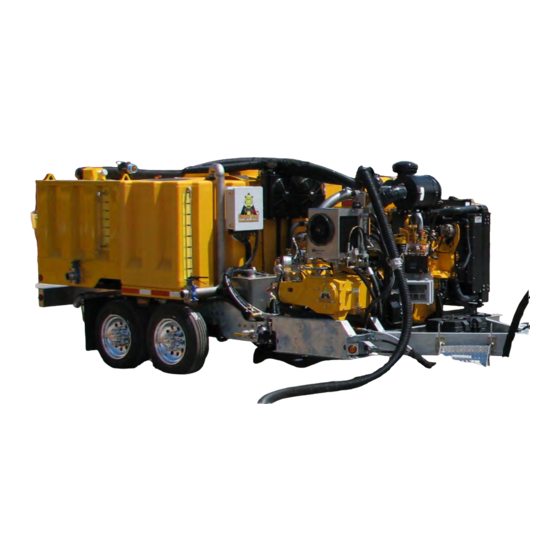
Section 2: Stripe Hog Systems SK2000 Water Blasting System Mounted On A Trailer Chassis plug on the chassis. Quick connect hydraulic hose 2.1 Stripe Hog System Introduction connectors and a 12 volt DC plug is provided to Introduction connect the optional HT1000 Ground Hog, HT2500... -
Page 18: Trailer Chassis
Section 2 - Stripe Hog Systems Trailer Chassis Coupler, Jack & Break-Away System Pintle Coupler Mount Bracket Trailer Jack Pintle Coupler Trailer Break-Away System & Battery on the swivel mount is removed to swivel the jack 2.2 Trailer Chassis down for use and up for travel. Insert the pin with The waterblasting system is mounted to a heavy the jack in the up or down position to secure the duty trailer with a welded galvanized steel frame,... -
Page 19: Ground Hog Landing Pad
Section 2 - Stripe Hog Systems Trailer Break-Away System The system includes a break-away system with a cable tether attached to the tow vehicle and the break-away switch that automatically applies the trailer brakes and stop the trailer if it should accidently disconnect from the tow vehicle while driving. -
Page 20: Trailer Mounted Trailer Engine
Section 2 - Stripe Hog Systems 2.4 Trailer Mounted Trailer Engine The ultra-high pressure system pump is powered by the onboard auxiliary diesel engine. The vacuum system, charge water pump and all other hydrauli- cally powered systems are powered by a hydraulic pump connected to the engine by a pulley and belt drive system. -
Page 21: Ultra-High Pressure System Water System
Section 2 - Stripe Hog Systems Clean Water Tank & Valves Clean Water Tank Drain Valve Clean Water Tank Clean Water Tank Fill Valve Clean Water Tank Site Tube vides a quick view of the water level from outside 2.5 Ultra-High Pressure the trailer during filling operations. - Page 22 Section 2 - Stripe Hog Systems Wastewater Bladder Drain Valve the tank to help ensure that no debris enters the system. Additionally, the tank should be flushed frequently with clean, fresh water to prevent the accumulation of debris that may accidently enter the tank.
- Page 23 Section 2 - Stripe Hog Systems an accurate indication of the water level during filling operations only. It is not a reliable level indicator during operation when the dirty water transfer pump is being used to collect recovered wastewater. Use actual blasting time during operation with an average pump consumption of 5 gallons (19 liters) per minute to estimate the remaining clean water in the tank.
- Page 24 Section 2 - Stripe Hog Systems Two Stage Filter System A) 10 Micron Filter B) 1 Micron Filter Filters Operating with dirty filters can cause: • Unwanted particles forced through the filter A two stage filter system in the supply line from resulting in premature failure of the parts.
- Page 25 Section 2 - Stripe Hog Systems Ultra-High Pressure System Pump Components High Pressure Gauge Packing Water & Lubrication Valves Dump (Diverter) Valve Manual Bypass Valve High Pressure Pump Manifold Rupture Disc Ultra-High Pressure System Pump CAUTION The ultra-high pressure system pump (UHP) is a positive displacement pump that requires a con- stant water supply from the charge water pump at LOW CHARGE WATER PRESSURE CAN qUICKLY DAMAGE...
- Page 26 Section 2 - Stripe Hog Systems CAUTION THE TRAILER ENGINE MUST BE SHUTDOWN TO DISENGAGE AND STOP THE UHP PUMP FROM ROTATING. IF LOW CHARGE WATER PRESSURE IS INDICATED OR A SERIOUS FAILURE OCCURS IN THE UHP PUMP OR HIGH PRESSURE SYSTEM, USE THE EMERGENCY STOP BUTTON ON THE TRAILER ENGINE CONTROL PANEL TO IMMEDIATELY SHUTDOWN THE UHP PUMP AND WATER BLASTING SYSTEM.
- Page 27 Section 2 - Stripe Hog Systems The shutoff cartridge is located inside the body of the diverter valve assembly. It is generally open and controlled by the DUMP VALVE switch in the cab switch panel. When the DUMP VALVE switch is on, the shutoff cartridge is closed by the hydrau- lic cylinder forcing all high pressure water to the blasting head.
- Page 28 Section 2 - Stripe Hog Systems When setting initial blasting pressure, always open the manual bypass valve completely, set the engine and UHP pump to maximum operating RPM and turn the DUMP VALVE switch on to close the diverter valve. Then slowly close the manual bypass valve while monitoring the high pressure gauge until the desired operating pressure is achieved.
- Page 29 Section 2 - Stripe Hog Systems UHP Pump Bilge & Components Coupling Gland Nut Stuffing Box Pony Rod (Connecting Rod) Deflector Cooling/Lubrication Lines Plunger Bilge Packing Lube Water And Bilge Pump There are three (3) stuffing boxes, packing seals and plungers in the ultra-high pressure pump that must be continuously lubricated and cooled to achieve maximum life expectancy.
- Page 30 Section 2 - Stripe Hog Systems Packing lubrication and cooling water is drained from the UHP pump by a bilge pump drain system. The system is completely automatic and activated whenever the main circuit breakers are activated. A fuse in the outside terminal box protects the bilge pump circuit from an overload.
-
Page 31: Hog Head
The Hog Head (blasting head) assembly on op- tional Hog Tools or the Hog Rider is powered by the SK2000. A separate operation and maintenance manual for each Hog Tool selected are included with this manual. Refer those manuals for specific operation and maintenance instructions for the tools included with your SK2000 trailer. -
Page 32: Blasting Tool Connection
Section 2 - Stripe Hog Systems The castor wheel mount assemblies are threaded to provide spray bar/blasting head height adjustment. T-handle adjustment rods attached to each castor wheel assembly or threaded shafts with spacers and locknuts are used to move the wheels up or down. Blasting head height adjustment should be checked before each shift and the wheel castors should be inspected for damage and excessive wear daily. -
Page 33: Thru-Shaft, Spray Bars & Nozzles
Section 2 - Stripe Hog Systems Swivel Seal & Brass Backup Ring Swivel Nut Swivel Seal Weep Hole Thru-shaft Cover Grease Fitting Speed Sensor Brass Backup Ring Swivel Seal Thru-Shaft Motor Components be checked daily to ensure it is tight and that the 2.8 Thru-shaft, Spray swivel seal is not leaking. - Page 34 • Profile requirements per job specifications. Hog Head & Various Spray Bar Sizes Hog Technologies offers a variety of spray bar configurations to meet requirements of all types of removal projects. Examples of available spray bar configurations are included in the Operation section of this manual.
- Page 35 Section 2 - Stripe Hog Systems CAUTION BEFORE ATTACHING THE NEW SPRAY BAR TO THE HOG HEAD ASSEMBLY, ENGAGE PUMP AT LOW PRESSURE TO PURGE THE SYSTEM. ANY DIRT OR DEBRIS IN THE SYSTEM CAN CLOG NOZZLE ORIFICES AND CAUSE SYSTEM PRESSURE TO SPIKE EXCESSIvELY CAUSING DAMAGE TO COMPONENTS OR RUPTURE DISCS ON THE UHP PUMP TO BURST.
- Page 36 Section 2 - Stripe Hog Systems Good Nozzle Spray Pattern Nozzles Showing Bad Spray Pattern Nozzle Must Be Replaced Once the spray bar protector is removed and all If a nozzle rates as a 5 or higher on the Nozzle personnel are well clear of the blasting head, Quality Chart, it is worn or damaged and must be activate the high pressure system and set the...
- Page 37 Nozzle threads are damaged nozzle selection becomes easier. You can also When replacing nozzles make sure to check the contact Hog Technologies Customer Support toll flow and pressure rating. Use only nozzles with a free at (877) HOG-ROAD for assistance in select- manufacturer’s pressure rating of at least the UHP...
- Page 38 Section 2 - Stripe Hog Systems mend that you only use nozzles, high pressure hoses and fittings supplied by Hog Technologies to ensure the nozzles and other components are compatible with your ultra-high pressure system water blasting system. Shroud The shroud is the heavy duty stainless steel...
-
Page 39: High Pressure Hoses, Connections & Fittings
Blasting Head, Thru-Shaft Motor & Ultra High Pressure Hose 2.9 High Pressure Hoses, Connections & Fittings The ultra-high pressure hoses used in the SK2000 water blasting system are tough but not invincible. They require proper care and handling to achieve maximum life expectancy. - Page 40 Section 2 - Stripe Hog Systems operator and/or maintenance personnel inspect C) Hose has been kinked or subjected to a radius the ultra-high pressure hoses, hose connections tighter than its minimum bend radius. and fittings prior to the start of each shift, periodi- D) Hose has been crushed or stretched.
-
Page 41: Debris Recovery System
Section 2 - Stripe Hog Systems Debris Recovery System 2.10 Debris Recovery System WARNING Overview The vacuum system is powered by the trailer OPERATING THE WATER BLASTING SYSTEM WITH vACUUM hydraulic system and is activated whenever the IN EXCESS OF -7 IN HG (178 MM HG) WILL DAMAGE THE engine is running and the VACUUM switch in the OIL SEAL IN THE BLOWER GEAR CASE AND SUCK THE control panel is on. - Page 42 Section 2 - Stripe Hog Systems Ground Hog & Vacuum Hoses Vacuum Hoses The inside walls of vacuum hoses develop wear points caused from the high velocity of abrasive The primary vacuum hose runs from the cutoff debris traveling inside the hoses. The wear points ball valve connection on top of the debris tank to are most prevalent in the outside radius of tight the vacuum hose connection on the vacuum filter...
- Page 43 THE GREASE SPECIFIED IN THE MAINTENANCE MATRIX AND THE BLOWER MANUFACTURER. FAILURE TO LUBRICATE THE BEARINGS DAILY OR USING GREASE OTHER THAN THE GREASE SPECIFIED BY HOG TECHNOLOGIES AND THE BLOWER MANUFACTURER WILL vOID THE WARRANTY. Blower airflow is expelled through a silencer con- nected to the outlet side of the blower.
- Page 44 Section 2 - Stripe Hog Systems Filter And Filter Canister The vacuum filter canister houses the vacuum filter which protects the blower from debris. The filter should be checked at the beginning of each shift and periodically during operation. It is normal for some water vapor to travel from the debris tank to the vacuum filter canister where it will accumulate.
- Page 45 Section 2 - Stripe Hog Systems Debris Tank & Door Debris Tank Inflatable Door Seal Vacuum/Debris Tank The debris tank is constructed with stainless steel panels. The debris tank door has a manual locking system and watertight inflatable door seal. The pressurized door seal is supplied compressed air by the onboard air compressor.
- Page 46 Section 2 - Stripe Hog Systems A special filter bag (debris bag) is mounted on slid- ing retainer rods near the top the stainless steel liner inside the debris tank. The vacuum system creates vacuum in the tank and debris mixed with water from the Hog Head flows directly into the debris bag where solid debris and particles over 100 microns are trapped.
- Page 47 Section 2 - Stripe Hog Systems Wastewater Transfer Pump The debris transfer pump circuit is activated by the DIRTY WATER PUMP switch in the control panel. When the circuit is activated, a diaphragm pump on the chassis below the debris tank will trans- fer wastewater from the tank to the wastewater bladder.
- Page 48 Section 2 - Stripe Hog Systems Gravity Wastewater Drains Wastewater can also be drained by gravity by opening the drain valve located on bottom side of the tank. To use the gravity drain system, make sure the DIRTY WATER PUMP and VACUUM switches are off.
-
Page 49: Electrical System
Section 2 - Stripe Hog Systems Trailer Onboard Batteries Main Circuit Breakers 2.11 Electrical System 50 Amp Main Circuit Breakers The water blasting electrical system is powered and protected by heavy duty circuit breakers located on the front of the trailer near the bat- teries. - Page 50 Fuses & Relays In Outside Terminal Box Contact Hog Technologies Customer Service if you need assistance correcting a problem with the water blasting electrical system. Control Panel Switches and Gauges...
- Page 51 Section 2 - Stripe Hog Systems Charge Pump Activates the solenoid valve that supplies pres- surized hydraulic fluid to power the charge water pump. A green LED light in the switch indicates the charge pump is activated. Dirty Water Pump Activates the circuit for the diaphragm transfer pump that pumps wastewater from the debris tank sump to the wastewater bladder.
- Page 52 Section 2 - Stripe Hog Systems Door Seal Inflate/Deflate A three position rocker switch that inflates or de- flates the door seal. The center position is OFF. Move the switch to the INFLATE position to pres- surize the seal. Move the switch to the DEFLATE position to release the pressure in the seal.
-
Page 53: Hydraulic System
Section 2 - Stripe Hog Systems 2.12 Hydraulic System Overview The hydraulic system is powered by the trailer engine through a pulley and belt drive system. It is equipped with a pump, reservoir/cooling tank and in-line filters. A heat exchanger with thermostati- cally activated fans cool the hydraulic fluid during operation. - Page 54 Section 2 - Stripe Hog Systems Hydraulic System Filter Clean hydraulic fluid that has not been exposed to excessive temperature or become contaminated is essential to the performance of the system. As pumps, cylinders and components wear, they release tiny metal and rubber particles into the hydraulic fluid.
- Page 55 All hydraulic circuits and actuators require special procedures for bleeding air from the system after servicing components or replacing hoses. Contact Hog Technologies if you need assistance in bleed- ing the air from the hydraulic system. Hydraulic Hoses The hydraulic system operates at pressures of up to 3,000 psi (207 BAR).
- Page 56 NOTES...
-
Page 57: Water Blasting Operation
Hog trailer. Make sure you have read them care- an SK2000 water blasting system. This informa- fully and fully understand the trailer and all water tion is provided as a general guide and overview blasting components and systems in theory and of the process for educational purposes. -
Page 58: Pre-Operation Inspection
Section 3 - Operation 3.2 Pre-Operation Inspection The Pre-operation Inspection in this section and the Pre-Op Check List in Appendix 3 is provided as a guideline. Additional items should be added to the checklist as determined by company policy, your operating environment, and other factors unique to your situation. - Page 59 Section 3 - Operation Clean Water Tank Drain & Fill Valves 3. Connect the fill hose to the water source and flush hose for several seconds. 4. Open the water tank fill valve and connect the hose to the quick connect fill fitting. Secure the hose to the fitting with the cam-lock levers.
-
Page 60: Trailer & Ground Hog Setup
Section 3 - Operation Ground Hog Landing Pad Lowered To Pavement & Tie Down Strap 3.4 Trailer & Ground Hog Setup The following procedure is specifically intended for the Ground Hog water blasting tool. Other than unloading the unit from the landing pad, the pro- cedure described in this section will be the same for most other Hog Tools. - Page 61 Section 3 - Operation Trailer UHP Hose & Hydraulic Hose Connections Ground Hog With All Hoses & 12V Control Cord Connected & 12V Control Cord Outlet 8. Connect the vacuum hose to the trailer and deploy the hose to the Ground Hog. Make sure the hose is laid out so there are no sharp bends that could cause the hose to kink, then connect the hose to the Hog Head.
-
Page 62: System Startup Procedure
Section 3 - Operation Trailer Switch Panel & Pressure Gauges 3.5 System Startup Procedure Startup procedure/Activating Hydraulics: 1. Perform the Pre-Op Inspection Trailer Engine Control Panel & Engine Speed Control Switch 2. Turn the main circuit breakers on. 3. Make sure all switches, speed dials and control valves are in the OFF position or set at 0. -
Page 63: Setting Pressure Procedure
Section 3 - Operation 3.6 Setting Pressure Procedure 1. Position an operator at the trailer control panels and at the Hog Tool. 2. Make sure the head rotation control valve or speed dial is set to 0. 3. Position the Hog Head so the spray bar and nozzles are visible. - Page 64 Section 3 - Operation 10. Check all high pressure hose fittings and the Hog Head weep holes for leaks. 11. Turn the HEAD ROTATION switch on. Rotate the speed dial or control valve on the Hog Tool clockwise to test the spray bar rotation, then stop the spray bar.
-
Page 65: Blasting Procedure
You should also consider the desired Hog Technologies offers an on-site training pro- or expected profile of the blasted surface in your gram that dramatically reduces the learning curve selection. - Page 66 Section 3 - Operation Visual Impact Guide Before Blasting Operations Begin: • Evaluate the Pavement and Select a Spray Bar. • Strong pavement withstands high aggression spray bars. This is generally concrete or new asphalt. • Cracked pavement is weak and will require a less aggressive spray bars.
- Page 67 Section 3 - Operation 3. Turn CHARGE PUMP switch on, then start the engine and allow it run at idle speed. CAUTION THE UHP PUMP IS DIRECTLY DRIvEN BY THE ENGINE AND WILL BE DAMAGED IF THE ENGINE IS STARTED WITHOUT THE CHARGE PUMP ENGAGED.
-
Page 68: Routine Shutdown
Section 3 - Operation Water Blasting Operation Do’s and Don’ts • Do not blast over pavement markers/reflectors. Markers can damage the blast head and spray bar Do’s: and should be removed prior to blasting. • STOP blasting before stopping the Hog Tool. Blast- ing with the tool stopped will damage the pave- •... -
Page 69: Dumping Debris
Section 3 - Operation 11. Disconnect the UHP hose from the Hog Tool and install the protective caps on the hose and blasting head fittings to prevent contamination. 12. Disconnect the UHP hose from the trailer fitting and install the protective caps on the hose and trailer fittings to prevent contamination. - Page 70 Section 3 - Operation 5. Open the latches at the bottom of the debris 11. When the tank is clean install a new filter bag. Check that the bag is installed properly and tank door and open the door. It is normal for some water to pour out as the door opens so that the debris pump intake line is not blocked.
-
Page 71: Emergency Shutdown Procedure
Section 3 - Operation 3.10 Emergency Shutdown Procedure WARNING IF AN EMERGENCY SITUATION INVOLVING THE POTENTIAL FOR PERSONAL INJURY AND/OR EQUIPMENT DAMAGE OCCURS, THE OPERATOR SHOULD ALWAYS SELECT THE EMERGENCY SHUTDOWN PROCEDURE. THIS PROVIDES IMMEDIATE SHUTDOWN OF THE TRAILER AND ALL WATER BLASTING SYSTEMS TO REDUCE THE POSSIBILITY OF INJURY AND DAMAGE TO EQUIPMENT. -
Page 72: Transporting The Trailer
Make sure the trailer coupler height is adjusted General to match the pintle hitch height so the trailer When selecting a to tow the SK2000 trailer, make is level. sure that it is capable of towing the weight of the trailer with full fuel and water tanks. -
Page 73: Lubrication & General Maintenance
Section 4: Lubrication & General Maintenance 4.1 Lubrication & General CAUTION Maintenance Introduction Lubrication Points THE GENERAL MAINTENANCE PROCEDURES OUTLINED IN THIS SECTION MUST BE FOLLOWED EXACTLY TO You should become familiar with the location of all AvOID DAMAGING COMPONENTS AND/OR vOIDING THE components that require frequent lubrication and WARRANTY. -
Page 74: Lubrication & Grease Point Locations
Section 4 - General Maintenance 4.2 Lubrication & Grease Point Locations Stripe Hog Lubrication Chart 1 ITEM# COMPONENT DESCRIPTION ITEM# COMPONENT DESCRIPTION Vacuum Blower Silencer Exhaust Flap Hinges Debris tank Door Hinges Vacuum Canister Door Latches Debris tank Door Latches Vacuum Canister Door Hinges Debris tank Gas Lift Spring Bearings UHP Water Filter Retainer Ring Clamps... - Page 75 Section 4 - General Maintenance Lubrication & Grease Point Locations Stripe Hog Lubrication Chart 2 ITEM# COMPONENT DESCRIPTION ITEM# COMPONENT DESCRIPTION Debris Tank Kunkle Valve Charge Water System Valves Vacuum Canister Kunkle Valve UHP Pump Oil Sump Drain Valve Debris Tank Drain Valve Vacuum Blower Bearings Clean Water Tank Drain Valve Hydraulic Pump Drive Pulley Bearing...
-
Page 76: Standoff Adjustment Procedure
Section 4 - General Maintenance Typical Blasting Head Standoff Adjustment & Standard Setting (Note that the Hog Head shown is for reference purposes only) 4.3 Standoff Adjustment Procedure • Clearance for obstacles. The standoff should always be set high enough to provide enough The term “Standoff”... - Page 77 Section 4 - General Maintenance To set the standoff distance: 9. Before starting operations, confirm proper 1. Make sure the water blasting system is shut- clearance by moving the blast head slowly over down. a typical obstacle in the pavement on the cur- rent job while monitoring the clearance.
-
Page 78: Clean Water Filter Replacement
Section 4 - General Maintenance 4.4 Clean Water Filter Replacement 10 Micron Bag Filter CAUTION THE FILTER CANISTER LIDS CAN BE EJECTED FROM THE CANISTER IF THE RETAINER RING IS LOOSENED WHILE THE CHARGE WATER SYSTEM IS PRESSURIZED. THIS CAN RESULT IN DAMAGE TO THE FILTER AND COULD CAUSE INJURY TO PERSONNEL. - Page 79 Section 4 - General Maintenance Typical Filter Retainer Hand Bolt 1 Micron Filter Canister 3. Remove filter canister lid and retainer ring. 4. Remove the filter retainer bolt and filter. Then flush filter canister to remove debris and con- taminants with clean, fresh water. Clean Filter Installation 5.
-
Page 80: Bleeding Air From Charge Water Pump
Section 4 - General Maintenance 4.5 Bleeding Air From Charge Water Pump Air must be bled from the charge water system when the filters are changed, the clean water tank is run dry or anytime the charge water system is serviced. -
Page 81: Wear Brush Replacement
Section 4 - General Maintenance 4.6 Wear Brush Replacement The Hog Tool wear brush bristles will slowly wear during operation. Consequently, the wear brush will require adjustment periodically to keep the bristles in contact with the pavement to provide proper vacuum air flow. It will also need to be adjusted when the standoff distance is increased or when the shroud and/or wear brush is replaced. -
Page 82: Dirt Shield Replacement
Section 4 - General Maintenance 4.7 Dirt Shield Replacement The dirt shield should be inspected daily to ensure it is tightened properly and that the felt seal is in Dirt Shield good condition. Apply Anti-Seize Button Seal Use the following procedure to replace a damaged or worn felt seal: 1. -
Page 83: Nozzle Installation
Section 4 - General Maintenance Spray Bar Protector, Cotter Pin & Gasket Typical Blasting Head With Spray Bar Protector Installed Nozzle Replacement Procedure: 4.8 Nozzle Installation 1. Make sure the waterblasting system is shut- The condition of the nozzles is critical to removal down with the trailer in the service position. - Page 84 Section 4 - General Maintenance 8. Apply a light coat of anti-seize to the threads on the new nozzles. 9. Install the nozzles being careful not to get any anti-sieze on the seat area of the nozzle or the spray bar. 10.
- Page 85 Section 4 - General Maintenance Replacing the rupture disc: If a rupture disc bursts, find and correct the prob- lem that caused excessive pressure, then use the following procedure to replace the rupture disc. Refer to the drawing at the bottom of this page for additional reference.
-
Page 86: Swivel Seal Replacement
Section 4 - General Maintenance Thru-Shaft Cover Housing & Swivel Nut Swivel Tit In Thru-shaft Cover Housing 4.9 Swivel Seal Replacement The swivel seal must be inspected at the start of each shift and replaced at the first sign of leakage to avoid damage to the swivel nut and thru-shaft cover housing. - Page 87 Section 4 - General Maintenance 10. Install the lubricated swivel seal onto the 5. Once the brass back-up ring is removed, in- spect the swivel seal seat and the edges of swivel tit with the beveled edge facing down. Be sure the swivel seal is seated against the the seat in the back-up ring closely.
-
Page 88: Vacuum Canister & Filter
Section 4 - General Maintenance 4.10 Vacuum Canister & Filter The vacuum filter canister houses the vacuum filter to protect the blower from debris and should be checked at the beginning of each shift. It is normal for water vapor to travel from the debris tank to the vacuum filter canister and gradually accumulate. -
Page 89: Scheduled Maintenance
• Inspect and test for proper operation. Replace the SK2000 water blasting system. You should damaged, corroded or worn out pins imme- become familiar with the maintenance and lubri- diately. - Page 90 Section 5 - Scheduled Maintenance Bilge Pump And Automatic Switch Debris tank Transfer Pump And Automatic Weekly/50 Hours: Switch • Supply water to the high pressure pump stuff- Weekly/50 Hours: ing box sump and monitor the operation of the • Remove and clean the debris pump strainer bilge automatic switch, bilge pump and drain screen.
-
Page 91: Trailer Engine & Reduction Gear
Section 5 - Scheduled Maintenance 5.3 Trailer Engine & Reduction Gear Proper trailer engine maintenance is essential to the proper performance and reliability of the water blasting system. You should perform all recom- mended maintenance according to the manufac- turer’s recommendations. Maintenance schedules and procedures are outlined in the engine owner’s manual. -
Page 92: Hydraulic System Drive Belt
Section 5 - Scheduled Maintenance 5.4 Hydraulic System Drive Belt The primary drive belt that connects the engine to hydraulic pump is a special carbon fiber industrial belt designed for high horsepower applications. The ribbed drive belt is matched to grooved pul- leys and has very little stretch. - Page 93 Section 5 - Scheduled Maintenance Mounting Plate Bolts Drive Pulley Adjusting Bolt Note: 2. Rotate the adjusting bolt to move the pulley The procedure in this example is for the and pump to set the belt to the proper tension. Gates Sonic Tension Meter shown.
-
Page 94: High Pressure Hose Installation
Section 5 - Scheduled Maintenance 8. Tighten the mounting bolts securely. Note: Apply grease or anti-seize to the threads of the adjusting bolt each time the belt is ad- justed to help prevent corrosion and ensure the adjusting bolt will turn when adjustment is required. -
Page 95: Ultra High Pressure Pump Scheduled Maintenance
Section 5 - Scheduled Maintenance 5.6 Ultra High Pressure Pump Scheduled Maintenance The 40K UHP pump operates at very high pres- sure and has specific lubrication and maintenance requirements. Refer to the Maintenance Matrix in this section and the pump manufacturer’s op- erating and maintenance manual for lubrication specifications and maintenance schedules. - Page 96 Section 5 - Scheduled Maintenance 100 Hour Maintenance 200 Hour Maintenance Perform all daily and 100 hour maintenance along Perform all daily maintenance along with the items outlined in this section. with the items outlined in this section. • Check and tighten all mounting bolts and •...
-
Page 97: Checking Uhp Pump Oil Level & Changing Crankcase Oil
Section 5 - Scheduled Maintenance Crankcase Oil Level - Pump Running Crankcase Oil Level - Pump Shutdown 5 To 8 Hours is shutdown. It takes 5 to 8 hours for oil in the 5.7 Checking UHP Pump Oil Level upper sump to completely drain to the main sump &... - Page 98 Section 5 - Scheduled Maintenance 3. With the pump still engaged, reduce the en- gine RPM to idle and check the oil level in the sight gauge. The oil level should be half way between the ADD mark and the bottom of the sight gauge.
- Page 99 Section 5 - Scheduled Maintenance Draining the crankcase oil: 1. Make sure the water blasting system is shut- down with the trailer in the service position. 2. Remove the safety plug at the oil drain valve fitting. 3. Attach a drain hose to the valve fitting and route the hose to a suitable waste oil con- tainer capable of handling at least 6 gallons (23 liters) of oil.
-
Page 100: High Pressure Pump Univalve Service
Section 5 - Scheduled Maintenance Removing Univalves: 5.8 High Pressure Pump 1. Make sure the water blasting system is shut- Univalve Service down with the trailer in the service position. The Univalve cartridges will require service every 100 hours or if the following conditions are pres- 2. - Page 101 Section 5 - Scheduled Maintenance Univalves Installed In Head Figure 1: A. Univalve Body & Seat - B. Suction Valve 3. Set the valve cartridge in place. Rock the car- tridge slightly until it drops into position. Lapping a valve to the seat creates a unique suc- tion valve to Univalve cartridge seat seal.
- Page 102 Section 5 - Scheduled Maintenance LEGEND Shiny Line Indicates a cut or a crack Cuts caused by a leak Can be lapped if not too deep Cracks in the univalve Cannot be repaired, replace the univalve Shiny dot is a pit caused by calcium Can be lapped out “V”...
- Page 103 Section 5 - Scheduled Maintenance 13. Inspect the sealing surfaces on both pieces 17. Reassemble the Univalve with new O-rings and very carefully to determine whether to stop or seals. to complete another cycle. The shiny places 18. Lubricate the O-rings and seals with the grease are evidence of damage and/or wear.
-
Page 104: High Pressure Pump Stuffing Box Packing Replacement
When excessive water begins flowing 4. Use the 7/8” Allen wrench (Jetstream tool) through a stuffing box, the packing will need to supplied in the Hog Technologies tool system. be replaced. Insert the round end of wrench into the hole on the gland nut. - Page 105 Section 5 - Scheduled Maintenance Stuffing Box, Glandnut, Packing & Plunger Guide Bushing or Carbide Ring 8. Check the carbide guide bushing for nicks, cracks, breaks or excessive wear. Replace if necessary. 9. Check the plunger for scoring and wear. Polish or replace if necessary.
- Page 106 Section 5 - Scheduled Maintenance 15. Slide the plunger back against the pony rod. 18. Turn on the charge water pump and verify Reinstall the plunger coupling to the plunger that the lubrication water is flowing normally. and pony rod. Make sure both halves of the Use the metering valves to adjust water flow plunger coupler face the same way.
-
Page 107: Ultra-High Pressure Pump Assembly
Section 5 - Scheduled Maintenance PUMPS & FLUID ENDS 5.10 Ultra-High Pressure Pump Assembly 40,000 PSI UNx™ 3040 Fluid End Replacement Parts ITEM PART DESCRIPTION ITEM PART DESCRIPTION NUMBER NUMBER Item Part Description Item Part Description Item Part Description K26624 Deflector K55632 Manifold... -
Page 108: Dump Valve Assembly
Section 5 - Scheduled Maintenance 5.11 Dump Valve Assembly The dump valve should be inspected and lubricated every 200 hours to keep it operating properly. Replace components as required. Dump Valve Repair (Hydraulically operated) 1. Remove diffuser tube (2) with cartridge (3). 2. -
Page 109: Manual Bypass Valve
Section 5 - Scheduled Maintenance 5.12 Manual Bypass Valve The manual bypass valve should be inspected and lubricated every 200 hours to keep it operating properly. Replace components as required. Manual Bypass Valve Repair 1. Remove outlet adapter (11). Pull cartridge (3) out. If cartridge (3) is stuck together and not releasing pull the pin and cartridge body apart to inspect the seats for cuts and other damage. -
Page 110: Vacuum Blower Scheduled Maintenance
Section 5 - Scheduled Maintenance 500 Hour Maintenance (New Blower) 5.13 Vacuum Blower Perform all daily maintenance along with the items Scheduled Maintenance outlined in this section. Blower and Filter Canister The vacuum blower operates at an extremely high • Change blower gear case lubricating oil after RPM and has specific lubrication and maintenance the first 100 hours and every 500 hours there-... -
Page 111: Checking & Changing Blower Gear Case Oil
Section 5 - Scheduled Maintenance Typical Vacuum Blower Gear Case Drain, Oil Level & Oil Fill Plugs A. Drain Valve & Safety Plug B. Overflow Plug C. Breather/Oil Fill Plug Checking The Gear Case Oil Level 5.14 Checking & Changing 1. - Page 112 Section 5 - Scheduled Maintenance Changing the Gear Case Oil Draining the gear case: 1. Make sure the water blasting system is shut- down with the trailer in the service position and on level ground. 2. Remove the safety plug at the oil drain ball valve fitting.
-
Page 113: Vacuum Hose Replacement & Rotation Procedure
Section 5 - Scheduled Maintenance 5.15 Vacuum Hose Replacement & Rotation Procedure Debris buildup, kinks, clogs or leaks in the system will cause a reduction in airflow at the blasting head, reducing the efficiency of operation or caus- ing operations to stop completely. Debris buildup inside the hoses can be removed by periodically tapping the outside walls with a dead blow ham- mer while the system is operating at maximum... -
Page 114: Shroud Installation
Section 5 - Scheduled Maintenance Dirt Shield Apply Anti-Seize Button Seal Spray Bar & Dirt Shield Components Shroud Installed 5.16 Shroud Installation If the shroud becomes damaged, it must be re- placed following the steps outlined in this section. Removing the shroud: 1. - Page 115 Section 5 - Scheduled Maintenance Installing a new shroud: 1. Clean the bottom of the thru-shaft motor hous- ing of dirt and debris. 2. Place the new shroud on the housing and align the bolt holes. Insert the shroud bolts and tighten finger tight.
-
Page 116: Hydraulic System Scheduled Maintenance
Hydraulic fluid should be changed and the tank flushed on a regular schedule in accordance with the hydraulic component manufacture’s recom- mendations. Hog Technologies recommends changing the fluid at least once every 600 hours. Daily Inspection and Maintenance •... -
Page 117: Changing Hydraulic Fluid & Flushing Tank
Section 5 - Scheduled Maintenance 200 Hour Inspection and Maintenance • Change the filter in the return line. The filter removes any debris that may enter the system and should be changed every 200 hours or more frequently if necessary. •... -
Page 118: Winterization & Storage Procedures
Section 5 - Scheduled Maintenance Clean Water Tank Drain & Fill Valves For trailers operating daily during freezing weath- 5.20 Winterization & er, this method provides much quicker startup and Storage Procedures shutdown procedures. The procedure requires When operating the trailer in freezing tempera- a 50/50 mixture of water and glycol based RV tures, it is extremely important to properly win- potable water system antifreeze to be circulated... - Page 119 Section 5 - Scheduled Maintenance Use the following procedure to shutdown and winterize the water blasting system: 1. Shutdown high pressure water to the blast head by turning off the DUMP VALVE switch. 2. Turn the HEAD ROTATION switch off. 3.
- Page 120 Section 5 - Scheduled Maintenance 11. Remove the spray bar and store it. 12. Open the bleeder valve at the charge water pump and allow hoses to completely drain. With the valve still open, activate the pump briefly to pump out any remaining water, then close the valve.
- Page 121 Section 5 - Scheduled Maintenance 20. Follow the Shutdown Procedure to shutdown the waterblasting system and place the trailer in the service position. Then reconnect the safety switch hose. NOTICE: THE CHARGE PRESSURE SAFETY SWITCH DEACTIvATES THE DUMP vALvE WHEN CHARGE PRESSURE DROPS BELOW 30 PSI (2 BAR) TO ALERT THE OPERATOR AND PROTECT THE UHP PUMP.
- Page 122 Section 5 - Scheduled Maintenance Reactivating a trailer winterized with anti- 7. At this point you’re ready to continue with freeze: complete startup procedure. (Refer to the Note that the steps in this procedure are intended System Startup Procedure) to recover as much of the antifreeze from the system as possible.
-
Page 123: Thru-Shaft Motor Bearing Pre-Load
If you have any questions or require assistance, there are situations where the bearing preload please don’t hesitate to contact Hog Technologies will need to be reset after the Hog Head has been Customer Service at 772-223-7393. - Page 124 Section 5 - Scheduled Maintenance Tools and Materials Required Tools Supplies 2 - Medium Sized Flat Blade Screwdrivers • Anti-Seize 1 - Medium Sized Channel Lock Pliers • Grease Gun and Mobile Poly Rex EM Grease 1 - 3/4” (19 mm) Open End Wrench •...
- Page 125 Section 5 - Scheduled Maintenance Pressure Hose Figure 1: High pressure hose on top of the thru-shaft motor Figure 2: High pressure hose removed Step 1 Remove the High Pressure Hose Remove the high pressure hose from the top of the thru-shaft motor by turning the hand nut at the base of the hose counterclockwise.
- Page 126 Section 5 - Scheduled Maintenance Figure 5: Use two medium flat head screwdrivers to remove the thrust housing cap. Note that the bolts are loose and left in place to prevent thrust housing cap from falling and being damaged during removal. Step 3 Remove Thrust Housing Cap Use a 6 mm Allen wrench to remove the 6 Allen head bolts that secure the thrust housing cap to the...
- Page 127 Section 5 - Scheduled Maintenance Swivel Tit Assembly/Gland Nut Figure 7: Swivel Tit assembly/gland nut to be removed by turning counterclockwise with a 15/16” deep well socket or box end wrench. Step 4 Remove Swivel Tit Assembly/Gland Nut While holding the thru-shaft with the 3/4” (19 mm) open end wrench through the slot in the mo- tor base, use a 15/16 (24 mm) deep well socket or box end wrench to remove the swivel tit as-...
- Page 128 Section 5 - Scheduled Maintenance Seal Nut Jam Nut Figure 9: Jam nut and seal nut. Make sure to loosen Jam Figure 10: Use spanner (weldment tool) to turn seal nut. nut 4 full turns first. Step 5 Loosen Jam Nut and Set the Bearing Preload Thrust Housing Cap Bolts While holding the thru-shaft with the 3/4”...
- Page 129 Section 5 - Scheduled Maintenance WARNING WHEN LOOSENING THE SPANNER TOOL AND SWIvEL NUT 1/4 TURN TO SET THE BEARING PRELOAD OR WHEN TIGHTENING THE JAM NUT, IT IS CRITICAL THAT THE THRU-SHAFT IS HELD FIRMLY WITH THE 3/4” (19 MM) OPEN END WRENCH SO THAT IT DOES NOT MOvE AT ALL.
- Page 130 Section 5 - Scheduled Maintenance O-ring Swivel Tit Assembly Seal Seat & Gland Nut Figure 13: O-ring seal seat at the top of the thru-shaft Figure 14: Swivel tit assembly/gland nut installed on the greased and the threads below the seal coated thru-shaft and torqued to 50 Ft lbs.
- Page 131 Section 5 - Scheduled Maintenance Step 8 (Cont) Set the thrust housing cap on top of the thrust housing and carefully press it into the housing. Align the bolt holes in the cap to the threaded holes in the thrust housing. Apply anti-seize to the 3/8”...
- Page 132 If the thru-shaft motor is assembled properly, it will start on its own each time it is activated from this point forward. If it continues to stall on start up, contact Hog Technologies Customer Service for assistance. Once the initial run up is complete and with the...
- Page 133 Section 5 - Scheduled Maintenance...
- Page 134 Section 5 - Scheduled Maintenance...
- Page 135 Section 5 - Scheduled Maintenance...
- Page 136 Section 5 - Scheduled Maintenance...
-
Page 137: Sk2000 Maintenance Matrix
Section 5 - Scheduled Maintenance 5.22 SK2000 Maintenance Matrix EQUIPMENT COMPONENT INTERVALS LUBRICANT SPECIFICATIONS Drive Line Drive Shafts At Each Chassis Service Mobil PolyRex EM Grease Trailer engine Oil and Filter Refer To trailer Operating Manual Refer To Engine Operating Manual... - Page 138 NOTES...
-
Page 139: Appendix 1: Troubleshooting
Appendix 1: Troubleshooting Water Blasting System Troubleshooting PROBLEM CAUSE AND SOLUTION Noises & Vibrations Blower system noise. • Blower impellers are clogged with paint and debris. Disassemble and clean blower. Rebuild or replace if necessary. • Blower muffler is clogged. Clean muffler. •... - Page 140 Appendix 1 - Troubleshooting PROBLEM CAUSE AND SOLUTION UHP Pump & High Pressure System High pressure and/or charge pressure gaug- • Engine speed is too low and hydraulic system is es fluctuating or pulsing. not turning the charge pump at proper RPM. Raise engine speed to operating RPM.
- Page 141 Appendix 1 - Troubleshooting PROBLEM CAUSE AND SOLUTION Low blasting pressure at nozzles. • Engine speed is too low. Raise engine speed. • Worn or blown nozzles. Change nozzles. • Nozzles are leaking. Tighten or replace nozzles. • Oversized nozzles. Refer to chart to correct nozzle pattern.
- Page 142 Appendix 1 - Troubleshooting PROBLEM CAUSE AND SOLUTION Vacuum System Low vacuum pressure. • Engine speed is too low and hydraulic system is not turning the vacuum blower at proper RPM. Raise engine speed to operating RPM. • Vacuum filter canister door seal leaking. Clean or replace lid seal.
-
Page 143: Tools & Spare Parts
Appendix 2: Tools & Spare Parts... -
Page 144: Mobile Spare Parts System
Appendix 2 -Tools & Spare Parts... -
Page 145: Daily Report & Pre-Op Checklist
Appendix 3: Daily Report & Pre-Op Checklist 1-877-HOG-ROAD WWW. STRIPEHOGSUPPORT.COM... -
Page 146: Pre-Op Checklist
Appendix 3 - Daily Report & Pre-Op Checklist PRE-OP CHECK LIST Mobile Spare Parts & Tool System Water Blasting System F Mobile Spare Parts System Complete F Clean Water Tank Full & Not Leaking F Mobile Tool System Complete F Fittings, Sight Tubes F Wastewater Bladder Empty F Check Vac Hoses Not Damaged Trailer Running Gear &... -
Page 147: Nozzle & Spray Bar Configuration
Appendix 4: Nozzle & Spray Bar Configuration Nozzle Configuration Chart Hog Technologies SPRAY BAR NOZZLE CONFIGURATION CHARTS FOR ALL STRIPE HOG MODELS 1-877-HOG-ROAD WWW. STRIPEHOGSUPPORT.COM... -
Page 148: Spray Bar Configuration Charts
Appendix 4 - Spray Bar & Nozzle Configuration Spray BAR Configuration Charts 6”, 14 Nozzle Spray Bar - 4” lines - Medium Aggressive 4.48 GPM @ 36K PSI / 4.74 GPM @ 40K PSI 6”, 14 Nozzle Spray Bar - 4” lines - Most Aggressive 4.54 GPM @ 36K PSI / 4.8 GPM @ 40K PSI 1-877-HOG-ROAD WWW. - Page 149 Appendix 4 - Spray Bar & Nozzle Configuration 8” Medium Aggressive Set Up 4.46 GPM @ 36K / 4.73 GPM @ 40K PSI 8” Most Aggressive Set Up 4.68 GPM @ 36K / 4.95 GPM @ 40K PSI 07 07 13 13 1-877-HOG-ROAD WWW.
- Page 150 Appendix 4 - Spray Bar & Nozzle Configuration 8” & 10”, 16 Nozzle - Least Aggressive Set Up 4.42 GPM @ 36K PSI / 4.68 GPM @ 40K PSI 8” & 10”, 16 Nozzle - Medium Aggressive Set Up 4.48 GPM @ 36K PSI / 4.74 GPM @ 40K PSI 8”...
- Page 151 Appendix 4 - Spray Bar & Nozzle Configuration 14”, Least Aggressive Set Up 4.61 GPM @ 36K PSI / 4.88 GPM @ 40K PSI 11 11 09 09 09 09 09 11 11 14”, Medium Aggressive Set Up 4.64 GPM @ 36K PSI / 4.91 GPM @ 40K PSI 13 11 09 09 07 07 07 07...
- Page 152 Appendix 4 - Spray Bar & Nozzle Configuration Hog Technologies SPRAY BAR NOZZLE CONFIGURATION CHARTS FOR ALL STRIPE HOG MODELS 14”, 22” & 36”, 30 Nozzle - Rubber Removal and/or Curing Compound Removal - 30K to 33K PSI 07 07 07 07 07 07 07 07 07 07 07 07 8”...
-
Page 153: Nozzle Calculation Sheet
Appendix 4 - Spray Bar & Nozzle Configuration Nozzle Calculation Sheet 1-877-HOG-ROAD WWW. STRIPEHOGSUPPORT.COM... - Page 154 NOTES...
-
Page 155: Glossary Of Terms
Appendix 5: Glossary of Terms Water Blasting Terms 1 Micron Cartridge Filter - Traps smaller particles that may come from the clean water tank and pass through the charge pump. 10 Micron Bag Filter – Traps larger particles that may come from the clean water tank and pass through the charge pump. - Page 156 Appendix 5 - Glossary of Terms Debris Tank – Collects all debris removed from the road surface through the vacuum hose. Dirt Shield – Threaded flat washer that protects the lower radial bearing of the thru-shaft from dirt and debris. Diverter Valve –...
- Page 157 Standoff Distance – Distance from the spray bar to the surface. Stripe Hog – Ultra high pressure water blasting equipment manufactured by Hog Technologies to remove paint and rubber from road surfaces. Supply Valve – Located between the clean water tank and the charge pump that is used to control the flow of water.
- Page 158 NOTES...
-
Page 159: Customer Support & Support Web Site
CUSTOMER SERVICE HOT LINE - 772-223-7393 www.hogtechnologies.com www.stripehogsupport.com Hog Technologies will not be responsible for damages or loss caused by sub- stituted parts purchased locally or from another vendor or manufacturer. WARNING NEvER ATTEMPT TO USE COMMONLY AvAILABLE PLUMBING PARTS, FITTINGS, AND HOSES IN... - Page 160 Appendix 6 - Customer Support Stripe Hog Support Web Site Stripe Hog Customer Support Center Home Training Ambassador Club Marketing Stripe Hog Store Contacts You are here Home Mike Logout Typical Registration & Log On Window Welcome to the Stripe Hog Support (001) 772-223-7393 This number that will find an Center! available customer support representative 24/7.
- Page 162 3920 SE Commerce Ave Stuart, Florida 34997 (001) (772) 214-1714 P (001) 772-223-5461 F www.thehog.com Print Date 02/22/2019 Rev 0...
Need help?
Do you have a question about the SK2000 and is the answer not in the manual?
Questions and answers
sk 2000 machine is a problem on switching dump valve and vacuum valve that mains when i switch vacuum valve on dump valve is automatically become off
The issue may be due to the dump valve operating logic. When the vacuum switch is turned on, it activates the solenoid valve supplying hydraulic fluid to the vacuum blower. If the dump valve is hydraulically controlled and shares the same hydraulic circuit, turning on the vacuum could cause a pressure change that unintentionally opens the dump valve. Another possibility is an electrical or control system conflict where activating the vacuum switch sends a signal that overrides or shuts off the dump valve circuit.
This answer is automatically generated