Table of Contents
Advertisement
Quick Links
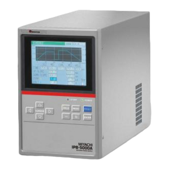
Thank you for purchasing the Miyachi Inverter-type Welding Power Supply IPB-5000A.
・ For correct use, read this operation manual carefully.
・ After reading, save it in a proper place where you can easily access to.
INVERTER-TYPE WELDING POWER SUPPLY
IPB-5000A
OPERATION MANUAL
CURSOR
WELDING POWER SUPPLY
IP B - 50 0 0 A
START
POWER
WELD
MENU
RESET
-
+
ENTER
J03M0756E-05
Advertisement
Table of Contents

Subscribe to Our Youtube Channel
Related Manuals for Miyachi IPB-5000A


Summary of Contents for Miyachi IPB-5000A
- Page 1 + ENTER WELDING POWER SUPPLY Thank you for purchasing the Miyachi Inverter-type Welding Power Supply IPB-5000A. ・ For correct use, read this operation manual carefully. ・ After reading, save it in a proper place where you can easily access to.
-
Page 2: Table Of Contents
IPB-5000A Table of Contents 1. Special Precautions··································································································· 1-1 (1) Safety Precautions································································································· 1-1 (2) Precautions for Handling ······················································································· 1-4 (3) Warning Labels for Safety ····················································································· 1-5 (4) Function Difference Depending on Model ····························································· 1-5 2. Features ······················································································································ 2-1 3. Packaging ··················································································································· 3-1 4. - Page 3 ⑤ Displacement Sensors ······················································································ 11-6 ⑥ Displacement Sensor Conversion Cables ························································ 11-6 12. Error Codes ············································································································ 12-1 13. Outline Drawing ····································································································· 13-1 (1) IPB-5000A-00-00/01/03/04···················································································· 13-1 (2) IPB-5000A-00-02/05······························································································ 13-2 14. Schedule Data Table······························································································ 14-1 (1) Weld SCHEDULE Setting ······················································································ 14-1 (2) PRECHECK Setting······························································································· 14-8 (3) COMPARATOR Setting ·························································································...
-
Page 4: Special Precautions
Never disassemble, repair or modify the Power Supply. These actions can cause electric shock and fire. If any part needs to be checked or repaired, contact Miyachi Corp. or your distributor for help. 1. Special Precautions... - Page 5 Do not tread on, twist or tense any cable. The power cable and connecting cables may be broken, and that can cause electric shock and fire. If any part needs to be repaired or replaced, consult Miyachi Corp. or your distributor.
- Page 6 IPB-5000A CAUTION Apply the specified source voltage. Application of a voltage out of the specified range can cause fire and electric shock. Do not splash water on the equipment. Water splashed over the electric parts, can cause electric shock and short circuits.
-
Page 7: Precautions For Handling
IPB-5000A (2) Precautions for Handling Install the Power Supply on a firm and level surface. If it is used inclined or on its side, it may have a malfunction. Also, provide 10 cm clearance to the intake and exhaust for improving the effect of heat release (Refer to 5. -
Page 8: Warning Labels For Safety
TO TURN OFF MAIN CIRCUIT BREAKER AND WAIT FOR AT LEAST 5 MINUTES NOT TO GET AN ELECTRIC SHOCK. Location: the side surface of a plastic cover inside IPB-5000A Meaning: Danger Location: Output terminal cover inside IPB-5000A Meaning: Danger of Electrical Shock (4) Function Difference Depending on Model The function of “only for Model with Displacement Sensor”... -
Page 9: Features
IPB-5000A 2. Features The Miyachi IPB-5000A is an inverter-type power supply designed for spot welding and fusing. It is easy to move and install, as it is small in size and compact. In addition, the monitor function is provided which makes possible the judgment of defective or non-defective welding. -
Page 10: Packaging
IPB-5000A 3. Packaging Shipping Kit LIst Verify that contents of the container agree with the kit list. If you see any damage, please contact Miyachi Corp. Packaged Kit Quantity IPB-5000A Operation Manual Cable Clamp (Large) for fixing I/O Cable Cable Clamp (Small) for fixing I/O Cable 3. -
Page 11: Name And Functions Of Each Section
Displays the information such as setting of a weld schedule, monitored values of weld current, etc. ② POWER Lamp Lights up when the power switch is turned on to supply the power to IPB-5000A and IPB-5000A works normally. ③ START Lamp Lights up while the start signal is input to make the sequence start. - Page 12 IPB-5000A ⑤ CURSOR Key Moves the cursor upward/downward or to the right/left on Display Screen. ⑥ MENU Key Press MENU Key to display MENU Screen. ⑦ RESET Key Press RESET Key to reset the display of a trouble after removing the cause of the trouble when the trouble display is shown on Display Screen.
-
Page 13: Rear Panel
IPB-5000A (2) Rear Panel Rear Panel Input Breaker Cover Input/Output Terminal Cover ① INT.24V EXT.COM STOP SCH 1 SCH 2 SCH 4 SCH 8 SCH16 ② SCH32 SCH64 PARITY (WE1 STOP) WELD ON/OFF ERROR RESET COUNT RESET W.INTERRUPT PRG PROTECT ③... - Page 14 Before coupling with the connector, decide which mode is to be selected, RS-232C or RS-485 and confirm the communication mode. RS-232C is set at the factory shipment. Mismatching of the communication mode setting at IPB-5000A with the mode at PC results in malfunction. 4. Name and Functions of Each Section...
-
Page 15: Installation And Connection
Allow at least 10cm or more from the end of the Wiring Outlet projected at the Output Terminal Cover in the rear potion of IPB-5000A. As IPB-5000A should be air-cooled, do not install it in a closed area. [Front View]... -
Page 16: Connection
Numerals of (1) to (8) in the above figure represent the order of connection procedures in the following pages. * 1: All items are separately sold except IPB-5000A. * 2: The Voltage Detecting Cable is used only for Constant Voltage Control, Constant Current/Constant Voltage Combination Control and Constant Power Control. - Page 17 IPB-5000A. The ways of connecting the Input Terminal Block of Welding Transformer are different from each other, depending on the input voltage of IPB-5000A. Connect in such way as ① below in the case of 200V System (200 to 240V) and as ②...
- Page 18 (See 4.(2)④) in the rear panel of IPB-5000A to Welding Transformer. (3) Connecting Start Cable Connect Start Cable from Terminal Strip for External Input/Output Signal (See 4.(2)①) in the rear panel of IPB-5000A to Terminal Strip for Start Switch in Welding Head. (4) Connecting Voltage Detecting Cable...
- Page 19 232C or RS-485 and confirm the communication mode (See 6.(9)②(c)COMM MODE for the selection of RS-232C and RS-485). Mismatching of the communication mode setting at IPB-5000A with the mode at PC results in malfunction. RS-232C is set at the factory shipment.
- Page 20 IPB-5000A (8) Connecting Displacement Sensor (only for model with Sensor) Install firmly Displacement Sensor not so as to rattle in reference to the figure below. Adjust sensor so that shaft of sensor Displacement Detecting retracts halfway Plate when electrode is at bottom.
-
Page 21: Description Of Display Screens
An example of the operation for the use of Welding Power Supply is shown as follows: 1. Start up IPB-5000A 2. Press MENU Key in the front panel to display MENU Screen 3. Move the cursor ( ) to SCHEDULE Key in MENU Screen and press ENTER Key to display SCHEDULE Screen 4. -
Page 22: Menu Screen
+/- key to complete such setting as input of a number or change of ON/OFF. IPB-5000A has various functions, which are set in the respective screens. Press MENU Key in Front Panel to display MENU screen. At the upper left of MENU screen, each function is displayed as a menu form. - Page 23 As the following, each item of (a) to (f) is described. (a) SCH # It denotes No. of weld SCHEDULE. 127 weld schedules as SCHEDULE#1 to #127 can be set on IPB-5000A. (b) TIME Time period of each movement in welding is set at the dimension of ms.
- Page 24 IPB-5000A ② Constant Voltage Control ③ Constant Current/Constant Voltage Combination Control ④ Constant Power Control 6. Discription of Display Screens...
- Page 25 IPB-5000A ⑤ SCHEDULE(2/2) Screen As the following, each item of (a) to (e) is described. (a) CONTROL Sets a control method for WE1 and WE2 respectively. CURR : Constant Current Control VOLT : Constant Voltage Control COMB : Constant Current/Constant Voltage Combination Control...
-
Page 26: Monitor Screen
IPB-5000A (4) MONITOR Screen In this screen, you can confirm the working condition during welding. The monitored data, that is, Current, Voltage, Power and Resistance in every schedule are displayed. Current is indicated in yellow solid line, Voltage is cyan, Power is green and Resistance is magenta. - Page 27 IPB-5000A (d) RESIST The waveform of Resistance can be displayed. (e) SETUP The screen of SETUP can be displayed. (f) TOTAL COUNT The mode of a counter can be displayed. For details, see (9)④(c)COUNTER. (g) DISPLC The waveform of Displacement can be displayed.
-
Page 28: Comparator Screen
IPB-5000A (5) COMPARATOR Screen Set the upper and lower criterion of Current, Voltage, Power and Resistance for judging “Good” or “No Good” weld. If the monitored value is inside the criterion, Good is determined. If it is outside, No Good is determined. -
Page 29: Envelope Screen
IPB-5000A (6) ENVELOPE Screen Here, the envelope waveform is prepared. The function of Envelope is to draw a waveform (here, calling Envelope Waveform) having allowable criteria based on a standard waveform (an average actual weld waveform) and compare a monitored actual weld waveform with the Envelope Waveform in order to judge “Good”... - Page 30 IPB-5000A (e) ON/OFF Set the activation or inactivation of the function. ON------------ Envelope function works OFF ---------- Envelope function does not work (f) NEW Selects a standard waveform. (g) EDIT Changes INTERVAL, OFFSET or ON/OFF one another. (h) COPY Makes a copy of the data of Envelope Waveform.
- Page 31 IPB-5000A ② Select NEW Button and press ENTER Key to draw a standard waveform. ③ Select MON Button and press ENTER Key to draw a standard waveform from a monitored waveform. ④ Select CURR Button and press ENTER Key to draw the standard waveform of a current waveform.
- Page 32 IPB-5000A ⑥ INTERVAL sets the time period from the beginning to end of Envelope waveform. OFF-SET sets a plus (+) and minus (-) allowable value. Concerning ON/OFF, ON should always be selected when using Envelope function. If OFF is selected, no Envelope function works.
-
Page 33: Precheck Screen
IPB-5000A (7) PRECHECK Screen Set the period of a weld time and a control voltage for Resistance PRECHECK in this screen. The function of Resistance PRECHECK is to flow lower current in Constant Voltage Control method just before supplying the weld current and see if work pieces to be welded are correctly positioned by the use of the measured value of current then. -
Page 34: Control Screen
IPB-5000A (8) CONTROL Screen Depict the screens of setting Weld Stop Function, Weld Time Comparator, etc. (a) INPUT Selects the type of Weld Stops. : External Input, WE1 Stop Input and Interrupt Input are effective. DISPLC : Weld Stop works at the set displacement value (only for Sensor equipped). - Page 35 IPB-5000A (f) DELAY TIME Sets Delay Time, the time period from Weld Stop to the time when a final displacement is measured (only for Sensor equipped). The setting range is from 0 to the time period of HOLD TIME (See (3)①(b)).
-
Page 36: Status Screen
IPB-5000A (9) STATUS Screen Change the initial setting of IPB-5000A here in this screen. According to customer’s preference, precise setting can be obtained. ① STATUS (1/2) Screen (a) WELD TRANS Set a transformer. Select it between ITD-360A6 and ITB-780A6. Do not select ITE-142A6. - Page 37 IPB-5000A (e) SCHEDULE# Fixes the method of how to select a schedule. EXT. (NP): Select a schedule by closing a schedule-selecting terminal on Rear Panel EXT. (P) : Select a schedule by closing a schedule-selecting terminal and a parity terminal on Rear Panel.
-
Page 38: ② Status (2/2) Screen
IPB-5000A ② STATUS (2/2) Screen (a) TRANS SCAN MODE Set the scan mode of transformers. Does not work in Model with Displacement sensor. OFF : No scan mode is used. ON : A SCHEDULE is performed. 1-2 : Consecutive 2 SCHEDULE’s are performed. - Page 39 IPB-5000A (f) NO CURR MONITOR START Set the starting time (Period for Neglect) of no-current supplying monitor. No-current supply is not detected during the Period for Neglect from the start of current supply. (g) PW MONITOR START Set the starting time (Neglect) of pulse width monitor.
-
Page 40: ③ Error Setting Screen
IPB-5000A ③ ERROR SETTING Screen The signals output at the occurrence of an error (NG Signal/Caution Signal) can be set item by item. (a) OFF/ON OFF : NG Signal is output. The input of Start Signal is not accepted at the occurrence of Caution Signal is output. - Page 41 IPB-5000A (c) COUNTER Set the mode of Counter. TOTAL Count-up (increment of +1) is done despite the result of the judgment in monitoring when the current is supplied. Judgment in Monitor Counting Manner GOOD Count-up CAUTION Count-up Count-up GOOD Count-up is done if the judgment is GOOD in current-supplied monitoring.
-
Page 42: Basic Operation
The example of a basic operation is described, using a transformer ITB-780A6 and a control method of Constant Current Control. (1) Connect correctly Welding Transformer ITB-780A6 and peripheral equipments to IPB-5000A, referring to the connection way (5.Installation and Connection). (2) Turn on the Breaker. (3) Press MENU key on Front Panel to display MENU Screen. - Page 43 IPB-5000A (5) Press MENU Key on Front Panel to display MENU Screen. Move the cursor ( ) to SCHEDULE and press ENTER Key to display SCHEDULE Screen. Move the cursor ( ) to each place and set the values of the table in the following page to each place by +/- Key.
- Page 44 IPB-5000A (7) Press WELD Key on Front Panel to light up WELD Lamp (LED). I P B - 5 0 0 0 A START P OW ER WELD MENU RESET CURSOR - + ENTER WELDING POWER SUPPLY (8) Set ON (Closed circuit) to WELD...
-
Page 45: External Interface
IPB-5000A 8. External Interface (1) Connection Diagram for External Input/Output Signals ① When contacts on PLC are used as input signal 24VDC INT.24V EXT.COM STOP SCH 1 SCH 2 SCH 4 SCH 8 SCH16 SCH32 SCH64 PARITY(WE1 STOP) WELD ON/OFF... -
Page 46: ② When Npn Transistor (Sink Type) On Plc Is Used As Input Signal
IPB-5000A ② When NPN transistor (sink type) on PLC is used as input signal 24VDC INT.24V EXT.COM STOP P L C SCH 1 SCH 2 SCH 4 SCH 8 SCH16 SCH32 SCH64 PARITY(WE1 STOP) WELD ON/OFF ERROR RESET COUNT RESET W.INTERRUPT... -
Page 47: ③ When Pnp Transistor (Source Type) On Plc Is Used As Input Signal
IPB-5000A ③ When PNP transistor (source type) on PLC is used as input signal P L C 24VDC INT.24V 24VDC EXT.COM STOP SCH 1 SCH 2 SCH 4 SCH 8 SCH16 SCH32 SCH64 PARITY(WE1 STOP) WELD ON/OFF ERROR RESET COUNT RESET W.INTERRUPT... -
Page 48: ④ When Solenoid Valves Are Activated By The Use Of An External Power Supply
IPB-5000A ④ When solenoid valves are activated by the use of an external power supply 24VDC 120VAC 24VDC SOL POWER SOL 1 SOL 2 SOL COM ⑤ When solenoid valves are activated by the use of an internal power supply 24VDC INT.24V... - Page 49 IPB-5000A Pin No. Description 1ST STAGE Intput Terminal. Closing of this Pin makes SOL1 Terminal of Pin 32 close. As the current-supplying sequence does not start, the adjustment or check of a squeeze location can be done. When closing 2ND STAGE Terminal at this location, the weld at the optimum squeeze location can be obtained.
- Page 50 IPB-5000A Pin No. Description Interrupt Input Terminal. The function is changed in dependence on the selection of WELD STOP (INPUT) at 6.(8)CONTROL Screen. * In the case of OFF selected at INPUT, When this Pin is closed while the sequence works at WE1 (W1), COOL (CO) and WE2(W2), the sequence skips to HOLD.
- Page 51 Closed at the time when weld current is ready for being supplied. Open at WELD OFF or in the occurrence of NG. POWER ON Closed in the occasion when the power supply of IPB-5000A is turned on. The rated capacity of a contact is 24VDC 20mA (Semi-conductor switch used).
-
Page 52: Schedule No. And Schedule Select Terminals
IPB-5000A (3) Schedule No. and Schedule Select Terminals Schedule No. : SCHEDULE# Blank: Open ●:Closed SCHEDULE# SCH 1 SCH 2 SCH 4 SCH 8 SCH16 SCH32 SCH64 PARITY ● ● ● ● ● ● ● ● ● ● ● ●... - Page 53 IPB-5000A Schedule No. : SCHEDULE# Blank: Open ●:Closed SCHEDULE# SCH 1 SCH 2 SCH 4 SCH 8 SCH16 SCH32 SCH64 PARITY ● ● ● ● ● ● ● ● ● ● ● ● ● ● ● ● ● ● ●...
- Page 54 IPB-5000A Schedule No. : SCHEDULE# Blank: Open ●:Closed SCHEDULE# SCH 1 SCH 2 SCH 4 SCH 8 SCH16 SCH32 SCH64 PARITY ● ● ● ● ● ● ● ● ● ● ● ● ● ● ● ● ● ● ●...
-
Page 55: Time Chart
IPB-5000A 9. Time Chart (1) Fundamental Sequence 2ND STAGE SOL2 Output Weld Current END Output GOOD Output NG Output CAUTION Output Symbol: SQ: Squeeze Time RC: Resistance Pre-check Time CP: Resistance Judgment Time (1ms) U1: Upslope 1 Time W1: 1st Weld Time... - Page 56 IPB-5000A ② In the case of DATA OUTPUT at COMM CONTROL, Communication data output time is included. Communication Speed Calculation Mode Setting (CALCULATION MODE) Setting NORMAL FAST (COMM SPEED) 9600bps 330ms Max. 280ms Max. 19200bps 275ms Max. 225ms Max. 38400bps 245ms Max.
-
Page 57: Determination Of Weld Schedule
IPB-5000A (2) Determination of Weld Schedule Weld Schedule is determined after Chattering Prevention Time, “START SIG. TIME” elapses from the input of Start Signal. ( A ) ( B ) Period set at Period set at START SIG. TIME START SIG. TIME... -
Page 58: Behavior Of Start Sig. Hold
IPB-5000A (3) Behavior of START SIG. HOLD * NO HOLD Setting: If Start Signal is made open during the period from SQ to W2, a weld sequence is broken off on the way and results in E13: CYCLE ERROR. Even if Start Signal is made open during HO, the weld... -
Page 59: Behavior Of End Sig. Time
IPB-5000A (4) Behavior of END SIG. TIME * HOLD: When 2ND STAGE Signal is closed for 10ms or less, END or GOOD Signal is output for 10ms. When 2ND STAGE Signal is closed for the longer period than 10ms, END or GOOD Signal is output for the closed period. -
Page 60: Behavior Of Sol1 And Sol2
IPB-5000A (5) Behavior of SOL1 and SOL2 SOL1 Output works by the Input of 1ST STAGE. When 1ST STAGE Input is open, SOL1 Output also becomes open if it is before the start of a weld sequence. After the start of a sequence, even if 1ST STAGE Input is open, SOL1 Output keeps closed until the sequence comes to an end. -
Page 61: Error" Or "Caution" In Precheck
IPB-5000A (6) “Error” or “Caution” in PRECHECK An example of weld sequence is shown, representing that a current goes out of the range between the upper and lower limit set in PRECHECK Screen with an error signal, “NG” or ”Caution” generated in the use of PRECHECK Current Supply function. -
Page 62: At Occurrence Of "Error" Or "Caution
IPB-5000A (7) At Occurrence of “Error” or “Caution” A sample weld sequence is shown, which represents the occasion where NG or CAUTION is produced while current is supplied. 2ND STAGE SOL2 Output Weld Current Sequence is not performed after NG or Caution is produced. -
Page 63: Behavior In Trans Scan Mode
IPB-5000A (8) Behavior in TRANS SCAN MODE ① OFF Setting It is a setting of the case where Transformer Selector MA-650A is not used. The behavior is the same as the one in (1) Fundamental Sequence. Those settings mentioned below in ② through ⑥ are the ones of the case where Transformer Selector MA-650A is used. -
Page 64: ③ 1-5 Setting
IPB-5000A ③ 1-5 Setting Firstly, weld current is supplied on the first selected SCHEDULE No. and then on the consecutive 5 SCHEDULE No.’s including the first selected No. in turn . In this occasion, weld current is supplied through the transformer selected at Transformer No. -
Page 65: ④ 1-2 Setting
IPB-5000A 1) In the case of OFF or BI-DIRECTION at COMM CONTROL, CALCULATION MODE Display Screen NORMAL FAST 310ms SCHEDULE 360ms Note) MONITOR 205ms 155ms values tables show maximum COMPARATOR 380ms 330ms ones. ENVELOPE 515ms 465ms PRECHECK 220ms 170ms CONTROL... -
Page 66: ⑤ 1-3 Setting
IPB-5000A ⑤ 1-3 Setting Similarly in the following part, weld current is supplied on the consecutive 3 SCHEDULE No.’s. Weld current is supplied through the transformer selected at Transformer No. (TR#) in each SCHEDULE Screen. ⑥ 1-4 Setting Weld current is supplied on the consecutive 4 SCHEDULE No.’s. -
Page 67: Movement Of Displacement Sensor
IPB-5000A (9) Movement of Displacement Sensor Weld Current DELAY TIME Displacement Symbol: SQ: Squeeze Time WD: Work Detecting Time (0.4ms Max) RC: Resistance Pre-check Time CP : Resistance Judgment Time (1ms) W1: 1st Weld Time CO : Cool Time W2: 2nd Weld Time... -
Page 68: External Communication Function
IPB-5000A 10. External Communication Function (1) Introduction IPB-5000A can be used to set schedules from an externally-connected personal computor (abreviated as PC) or to read monitored data and several kind of status data. (2) Data Transmission Item Content Select either of the followings at STATUS Screen:... -
Page 69: Configuration
IPB-5000A (3) Configuration ① RS-485 Host computer Device No.1 Device No.2 Device No.31 RS-232C RS-485 … … RS-232C/RS-485 Conversion Adapter 31 Devices Max. Note 1: When controlling two or more Lasers with one host computer, register the device No. (COMM UNIT#) for each device. -
Page 70: Protocol
IPB-5000A (4) Protocol ① Single-directional Communication Mode (When DATA OUTPUT is selected at COMM CONTROL in STATUS Screen) 1) Monitor Data Data strings: !01001:1.49,1.51,0.51,0.55,00.7,00.3,2.01,2.03,0.61, 0.55,01.2,00.3,+01.250,010.0,010.0,-00.300 [CR] [LF] A: Device No. Fixed to 2 digits (00 to 31) B: Schedule No. -
Page 71: ② Bi-Directional Communication Mode
Inquiry about Model and ROM # Device No. I Version Example: Model of Device No. 1 and ROM Version, V00-00A From Host PC to IPB-5000A # ID1 ID2 I CR LF (# 0 1 I CR LF) From IPB-5000A to Host PC... - Page 72 ! ID1 ID2 SH1 SH2 SH3 : Data CR LF (! 0 1 0 3 1 H 0 1 : Data CR LF) Note) The set data is returned as confirmation from IPB-5000A. When data outside the range is set, the last data before setting is exactly returned.
- Page 73 # Device No. R Specified Code Example: Read Model of Transformer at Initial Setting (6.(9)STATUS Screen) in Device No. 01. From Host PC to IPB-5000A # ID1 ID2 R CD1 CD2 CD3 CR LF (# 0 1 R P 4 0 CR LF)
- Page 74 Error Reset # Device No. R E00 Example: Release troubles in Device No. 01. From Host PC to IPB-5000A # ID1 ID2 R E 0 0 CR LF (# 0 1 R E 0 0 CR LF) From IPB-5000A to Host PC...
-
Page 75: Data Code Table
IPB-5000A (5) Data Code Table ① Order Table of Schedule Data 1) Specific Data in accordance with Schedule No. (Schedule No.: 001 to 127) Character Range of Increment/ Order Item String Setting Decrement nnnn, Squeeze Time 0000 to 9999 nnn.n, Upslope 1 Time 000.0 to 100.0... -
Page 76: ② Order Table Of Monitor Data (Most Recent Monitor Value)
IPB-5000A Character Order Item Notes String 00: Closed Circuit of Schedule Select Terminal (No Parity) Schedule Select 01: Closed Circuit of Schedule Method Select Terminal (Parity Valid) 02: Select on Front Panel 00: 10ms Signal Output 01: 100ms Time 02: While Start Signal Output... -
Page 77: ③ Specified Code
IPB-5000A ③ Specified Code 1) Specifying of Weld Sequence (T) Dimension of “ms” is added to each data. Specified Range of Increment/ Item Code Setting Decrement Squeeze Time 0000ms to 999ms Upslope 1 Time 000.0ms to 100.0ms 0.2ms 1st. Weld Time 000.0ms to 100.0ms... - Page 78 IPB-5000A Specified Increment/ Item Range of Setting Code Decrement WE2 Monitor Voltage Upper Limit 0.00V to 9.99V 0.01V WE2 Monitor Voltage Lower Limit 0.00V to 9.99V 0.01V WE1 Monitor Power Upper Limit 00.0kW to 99.9kW 0.1kW WE1 Monitor Power Lower Limit 00.0kW to 99.9kW...
- Page 79 IPB-5000A 5) Reading of Monitored Value (M) Specified Code Item Display (n=0 to 9) WE1 Monitor Current (PEAK Value) n.nnkA WE2 Monitor Current (PEAK Value) n.nnkA WE1 Monitor Voltage (PEAK Value) n.nnV WE2 Monitor Voltage (PEAK Value) n.nnV WE1 Monitor Power nn.nkW...
- Page 80 IPB-5000A 8) Setting of Initial Setting Condition (P) Specified Item Contents Code 00: Closed Circuit of Schedule Select Terminal (No Parity) Schedule Select 01: Closed Circuit of Schedule Select Method Terminal (Parity Valid) 02: Select on Front Panel Start Signal Stabilizing 00: 1ms 01: 5ms、...
- Page 81 IPB-5000A 10) Control (Q) Specified Item Contents Code 00: Constant Current W1 Control Mode 01: Constant Voltage 02: COMBI W2 Control Mode 03: Constant Power Selection of W1 Weld 00: OFF Stop Input 01: Displacement 02: Current Selection of W2 Weld...
-
Page 82: Specifications
IPB-5000A 11. Specifications (1) Specifications Items Common Specification in IPB-5000A (1) Constant Current Control: Controls so that weld current can be the set current (2) Constant Voltage Control: Controls so that the voltage detected at V sensing cord connected across electrodes can be the set voltage... - Page 83 IPB-5000A Items Common Specification in IPB-5000A Upper/Lower Limit setting is possible for the only one waveform Envelope selected among Current, Voltage, Power and Resistance. When WE1 or WE2 reaches the designated value of Current or Voltage, WE1 moves to CO and WE2, to HO.
- Page 84 NORMALLY OPEN : Closed with NG generated Set at READY OUTPUT. READY Output WELD ON : Closed with Weld Current Supply ready Setting POWER ON : Closed with IPB-5000A turned on Operation Temperature 5 to 40℃, Environment Humidity 90% or less (No condensation) 11. Specifications...
- Page 85 IPB-5000A IPB-5000A-00-00/03 IPB-5000A-00-01/02/04/05 Three-phase, 200 to 240VAC Three-phase, 380 to 480VAC (50 Hz / 60 Hz) (50 Hz / 60 Hz) Weld Power (Voltage cannot be selected. (Voltage cannot be selected. Supply Fixed to a customer-specified Fixed to a customer-specified voltage in factory shipment.)
-
Page 86: Optional Items (Separately Sold)
IPB-5000A (2) Optional Items (Separately Sold) ① Input Cables PK-01855-□□□ If a customer procures the cable by oneself, prepare it in accordance with the following right-hand specifications. Branch Length Type Specifications of Standard Cable -002 Rated Voltage 600VAC min. -005 Section Area min. -
Page 87: ③ [Sens] Cables Sk-05741
IPB-5000A ③ [SENS] Cables SK-05741 Item Branch No. Length (m) -002 [SENS] Cable -005 SK-05741 -010 ④ Start Cables A-03081 Item Branch No. Length (m) -001 Start Cable A-03081 -002 ⑤ Displacement Sensors Item Manufacturer GS-1630A ONO SOKKI Co. Ltd. -
Page 88: Error Codes
E-01 SYSTEM ERROR is displayed on control system of E-01 ERROR again, repair is required. IPB-5000A. Contact Miyachi Corp. Check all set data. The following is assumed to cause the data stored in memory to be corrupted. *Strong power noise or electrostatic noise... - Page 89 IPB-5000A Error Contents Cause Corrective Action Code Short-circuit wire is cut Connect Pin 1 to Pin 3 on rear terminal E-07 ABORT between Pin 1 and Pin 3 strip. STOP on rear panel. *Check the pressing force, electrode contact and wire connection of weld head.
- Page 90 IPB-5000A Error Contents Cause Corrective Action Code Current is out of range between upper limit *Check weld pickup (contamination) of PRECHECK and lower limit set electrodes, contact of electrodes and E-15 ERROR PRECHECK Screen work pieces. when PRECHECK *Check range set at PRECHECK Screen.
- Page 91 IPB-5000A Error Contents Cause Corrective Action Code *Check work pieces, welder and Measured displacement is DISPLACEMENT welding power supply voltage. E-26 out of upper limit set at ERROR (HIGH) *Check range set at CONTROL CONTROL Screen. Screen. *Check work pieces, welder and...
-
Page 92: Outline Drawing
IPB-5000A 13. Outline Drawing (1) IPB-5000A-00-00/01/03/04 Dimensions in mm 13. Outline Drawing 13-1... -
Page 93: Ipb-5000A-00-02/05
IPB-5000A (2) IPB-5000A-00-02/05 Dimensions in mm 13. Outline Drawing 13-2... -
Page 94: Schedule Data Table
IPB-5000A 14. Schedule Data Table (1) Weld SCHEDULE Setting 14. Schedule Data Table 14-1... - Page 95 IPB-5000A 14. Schedule Data Table 14-2...
- Page 96 IPB-5000A 14. Schedule Data Table 14-3...
- Page 97 IPB-5000A 14. Schedule Data Table 14-4...
- Page 98 IPB-5000A 14. Schedule Data Table 14-5...
- Page 99 IPB-5000A 14. Schedule Data Table 14-6...
- Page 100 IPB-5000A 14. Schedule Data Table 14-7...
-
Page 101: Precheck Setting
IPB-5000A (2) PRECHECK Setting COMP CURR COMP CURR ITEM ITEM TIME VOLT TIME VOLT SCH# SCH# SCH1 SCH28 SCH2 SCH29 SCH3 SCH30 SCH4 SCH31 SCH5 SCH32 SCH6 SCH33 SCH7 SCH34 SCH8 SCH35 SCH9 SCH36 SCH10 SCH37 SCH11 SCH38 SCH12 SCH39... - Page 102 IPB-5000A COMP CURR COMP CURR ITEM ITEM TIME VOLT TIME VOLT SCH# SCH# SCH55 SCH84 SCH56 SCH85 SCH57 SCH86 SCH58 SCH87 SCH59 SCH88 SCH60 SCH89 SCH61 SCH90 SCH62 SCH91 SCH63 SCH92 SCH64 SCH93 SCH65 SCH94 SCH66 SCH95 SCH67 SCH96 SCH68...
- Page 103 IPB-5000A ITEM ITEM COMP CURR COMP CURR TIME VOLT TIME VOLT SCH# SCH# SCH113 SCH121 SCH114 SCH122 SCH115 SCH123 SCH116 SCH124 SCH117 SCH125 SCH118 SCH126 SCH119 SCH127 SCH120 14. Schedule Data Table 14-10...
-
Page 104: Comparator Setting
IPB-5000A (3) COMPARATOR Setting 14. Schedule Data Table 14-11... - Page 105 IPB-5000A 14. Schedule Data Table 14-12...
- Page 106 IPB-5000A 14. Schedule Data Table 14-13...
- Page 107 IPB-5000A 14. Schedule Data Table 14-14...
- Page 108 IPB-5000A 14. Schedule Data Table 14-15...
- Page 109 IPB-5000A 14. Schedule Data Table 14-16...
- Page 110 IPB-5000A 14. Schedule Data Table 14-17...
-
Page 111: Control Setting
IPB-5000A (4) CONTROL Setting 14. Schedule Data Table 14-18... - Page 112 IPB-5000A 14. Schedule Data Table 14-19...
- Page 113 IPB-5000A 14. Schedule Data Table 14-20...
- Page 114 IPB-5000A 14. Schedule Data Table 14-21...
- Page 115 IPB-5000A 14. Schedule Data Table 14-22...
- Page 116 IPB-5000A 14. Schedule Data Table 14-23...
- Page 117 IPB-5000A 14. Schedule Data Table 14-24...
-
Page 118: Status Setting
IPB-5000A (5) STATUS Setting STATUS WELD TRANS WELD TIME START SIG.TIME START SIG.HOLD SCHEDULE# END SIG.TIME MONITOR MODE CALCULATION MODE LCD CONTRAST TRANS SCAN MODE COMM CONTROL COMM MODE COMM UNIT# COMM SPEED NO CURR MONITOR START PW MONITOR START...
Need help?
Do you have a question about the IPB-5000A and is the answer not in the manual?
Questions and answers