Table of Contents
Advertisement
W ELD IN G P OW ER S UP PL Y
W ELD IN G P OW ER S UP PL Y
IN DICATOR
FIN E SPOT -
WELD
POWER
READY
START
WELD
T ROUBLE
T ROUBLE
RESET
PROGRAM
WELD
MONITOR
I/ O
C OIL IN
Thank you for purchasing the Miyachi Technos IS-120B Inverter-type Welding Power Supply.
・ This operation manual explains its method of operation and precautions for use.
・ Before using, read this operation manual carefully. After reading, save it in a proper place
where you can easily access to.
INVERTER-TYPE WELDING POWER SUPPLY
IS-120B-
OPERATION MANUAL
IS-120B
INVER TER
PULL
RS -485
00-□□
02-□□
03-□□
C O N T E N T S
・・・・・・・・・・・・・・・・・・・・・・・・
3. Name and Functions of
Each Section
・・・・・・・・・・・・・・・・・・・・
・・・・・・・・・・・・・・・・・・・・・・・・
・・・・・・・・・・・・・・・・・・・・・・
・・・・・・・・・・・・・・・・・・・・
EC Declaration of Conformity
・・・・・・・・・・・・・・
・・・・・・・・・
・・・・・・・・・・
・・・・・・・・・・・・・・・・・
・・・・・・・・・・・・・・・・・
・・・・・・・・・・・・・・・
・・・・・・・・・・・・・・・
I04M0607E-06
1-1 to 5
2-1
3-1 to 6
4-1 to 22
5-1 to 3
6-1 to 5
7-1
8-1
9-1 to 4
10-1 to 12
11-1
12-1 to 3
Advertisement
Table of Contents

Subscribe to Our Youtube Channel
Related Manuals for Miyachi IS-120B-00 Series


Summary of Contents for Miyachi IS-120B-00 Series
- Page 1 ・・・・・・・・・・・・・・・ EC Declaration of Conformity Thank you for purchasing the Miyachi Technos IS-120B Inverter-type Welding Power Supply. ・ This operation manual explains its method of operation and precautions for use. ・ Before using, read this operation manual carefully. After reading, save it in a proper place where you can easily access to.
-
Page 2: Special Precautions
IS-120B 1. Special Precautions (1) Safety Precautions CAUTION ! Before using, read "Safety precautions" carefully to understand the correct Denotes operations and practices that method of use. may result in personal injury or damage to the equipment if not correctly followed. •... - Page 3 That can cause electric shock, short circuits and fire. If any part needs to be repaired or replaced, consult Miyachi Technos Corp. or your distributor. Stop the operation if any trouble occurs.
- Page 4 IS-120B CAUTION Apply the specified source voltage. Application of a voltage out of the specified range can cause fire and electric shock. Do not splash water on the equipment. Water splashed over the electric parts, can cause electric shock and short circuits.
- Page 5 IS-120B (2) Precautions for Handling Install this Power Supply on a firm and level surface. If it is inclined, malfunction may result. For ventilation, provide 10 cm clearances to the intake and exhaust (See 9.(3)). Do not install this Power Supply in the following places: Damp places (where humidity is 90% or higher), dusty places, places where chemicals are handled, places near a high-frequency noise source, places where it is subjected to vibration and shock, hot or cold places...
- Page 6 IS-120B (3) Warning Labels for Safety DANGER WHEN INSPECTING INTERNAL, MAKE SURE TO TURN OFF MAIN CIRCUIT BREAKER AND WAIT FOR AT LEAST 5 MINUTES NOT TO GET AN ELECTRIC SHOCK. Location: IS-120B interior, side surface of acrylic cover. Location: IS-120B interior, side surface of acrylic cover. Output terminal cover.
- Page 7 IS-120B 2. Features The Miyachi Technos FINE SPOT-INVERTER IS-120B is an inverter-type power supply, large in capacity and specially designed to be used for spot welding and fusing. (*) In addition, it is small in size and convenient to move or shift. Monitor function is provided, which enables judging defective or non-defective welding.
-
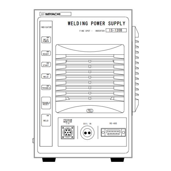
Page 8: Front Panel
IS-120B 3. Name and Functions of Each Section (1) Front Panel Front panel ① WELD POWER W E L D I N G P O W E R S U P P L Y I ND ICA TO R ② FINE SPOT - INVERTER IS -1 20B READY... - Page 9 IS-120B ④ [WELD] lamp (Green LED) This lamp stays lit while the welding current is flowing. ⑤ [TROUBLE] lamp (Red LED) This lamp lights up when trouble is detected. At this time, the program unit makes a peeping sound, and the work done by IS-120B is interrupted. ⑥...
- Page 10 IS-120B ⑨ [TOROIDAL COIL] connector For a toroidal coil connection. Used for secondary constant-current effective value control and secondary constant-power effective value control. (Toroidal coil is an option.) ⑩ [PROGRAM UNIT] connector Connects to Program Unit MA-627A. Used for welding schedule setting and/or reviewing monitor result.
-
Page 11: Rear Panel
④ Trip Button of Welding Power Supply Breaker Checks trip operation of the Breaker. Periodic checks are recommended. ⑤ Welding Transformer [I/O] connector For connecting [SENS] cable of welding transformer manufactured by Miyachi Technos Corp. ⑥ Terminal block for welding power output This terminal block is used to connect to the input of the welding transformer. - Page 12 IS-120B (3) MA-627A (Separately sold) WELDING SCHEDULE PROGRAM UNIT CURSOR MENU M A- 6 2 7 A TROUBLE ENTER RESET ⑥ ② ③ ④ ⑤ ① ① [TROUBLE RESET] key If this key is pressed while the [TROUBLE] lamp of IS-120B is lit, the lamp goes off.
- Page 13 IS-120B ⑥ Connector This connector is used to connect the circuit cable. Connect the other end of the cable to the [PROGRAM UNIT] connector of IS-120B. CAUTION Setting and change for each item cannot be done from the start signal receiving to the weld sequence end.
- Page 14 IS-120B 4. How to Operate Screens Letters used in the following explanation Hatched letters (000) An item for which a value must be input or ON/OFF is set. Move the cursor ( ) to the number or ON (or OFF) to be set or changed, and press [+ON/-OFF] key.
- Page 15 IS-120B (a) CONTROL # Input the identification No. of your IS-120B. If you have two or more units of IS-120B, input 0001 for the first one, 0002 for the second one, 0003 for the third one, and so on. (b) PROGRAMED DATE Input the date when the data is set.
- Page 16 IS-120B (3) SCHEDULE Screen Up to 15 welding schedules can be set on IS-120B. Those schedules are indicated as SCHEDULE #1 to #15. This screen is used to set the schedule No., length of weld time, welding current, and so on. This data can be indicated in the 12 modes as shown below, but the indicated items are the same in all the modes.
- Page 17 IS-120B Secondary constant-power Secondary constant-power effective value control ms mode effective value control CYC mode -SCHEDULE #01 CTRL 2 〈POWER RMS〉 -SCHEDULE #01 CTRL 2 〈POWER RMS〉 SQD SQZ WE1 COOL WE2 HOLD OFF SQD SQZ WE1 COOL WE2 HOLD OFF TIME 0000 0000 000 000 000 000 0000 ms TIME 000 000 00 00 00...
- Page 18 IS-120B ② IS-120B-00-□□. IS-120B-02-□□ Primary constant-current Primary constant-current effective value control ms mode effective value control CYC mode -SCHEDULE #01 CTRL 0 〈PRIMARY RMS〉 -SCHEDULE #01 CTRL 0 〈PRIMARY RMS〉 SQD SQZ WE1 COOL WE2 HOLD OFF SQD SQZ WE1 COOL WE2 HOLD OFF TIME 0000 0000 000 000 000 000 0000 ms TIME 000 000 00 00 00...
- Page 19 IS-120B Secondary constant-voltage Secondary constant-voltage effective value control ms mode effective value control CYC mode -SCHEDULE #01 CTRL 4 〈VOLTAGE RMS〉 -SCHEDULE #01 CTRL 4 〈VOLTAGE RMS〉 SQD SQZ WE1 COOL WE2 HOLD OFF SQD SQZ WE1 COOL WE2 HOLD OFF TIME 0000 0000 000 000 000 000 0000 ms TIME 000 000 00 00 00...
- Page 20 IS-120B (c) TIME Set the time for each operation during the welding. The unit of the time is ms or CYC. For each operation, see the time chart. Length of time added to SQZ only for the SQD / Squeeze delay time first weld after start signal in repeat operation Length of time until proper squeeze is SQZ / Squeeze time...
- Page 21 IS-120B (f) HEAT Set the welding current for WE1 and WE2 respectively. When CTRL is changed, the items to be set are changed. Primary constant-current effective value control Effective value of current Effective value of current Secondary constant-current effective value control Secondary constant-power effective value control Effective value of electric power Primary constant-current peak value control...
- Page 22 IS-120B (4) MONITOR Screen In this screen, you can confirm the working condition during welding. The monitored data in each schedule are displayed. (c) (d) -MONITOR SCHEDULE # 01 TIME CURR VOLT POWER PULSE WELD1 WELD2 VALVE1 VALVE2 STEPPER COUNT WELD COUNT STEP # This screen shows initial settings in HIGH range mode.
- Page 23 IS-120B (g) STEPPER COUNT The number of welds at the present step is displayed when the STEPPER (See (8).(e)) on the MODE SWITCH screen is turned on. (h) STEP # The present number of steps is displayed when the STEPPER on the MODE SWITCH screen is turned on.
- Page 24 IS-120B (6) COPY SETUP DATA Screen MA-627A has two memories to store the data (See the figure below). When MA-627A is connected to IS-120B, the data stored in the memory of IS-120B are displayed on the Monitor Panel. When the data are changed and the [ENTER] key is pressed, the contents of the memory of IS-120B are rewritten to the new setting.
- Page 25 IS-120B -COPY SETUP DATA IS-120B -----> MA-627A (MEMORY 1) IS-120B -----> MA-627A (MEMORY 2) IS-120B <----- MA-627A (MEMORY 1) IS-120B <----- MA-627A (MEMORY 2) SCHEDULE [01] -----> SCHEDULE [01]-[01] This screen shows initial settings. Move the cursor (→) to a necessary item among (a) to (d), then press [ENTER] key;...
- Page 26 IS-120B (7) SCHEDULE MODE Screen -SCHEDULE MODE MONITOR FIRST TIME 15ms DELAY-START SET 20ms NON-CURRENT PULSE COUNT 9 CURRENT MONITOR NUMBER WELD COUNT VALVE 1 VALVE 2 P/S RATIO 001.0 001.0 This screen shows initial settings. (a) MONITOR FIRST TIME MONITOR FIRST TIME sets the time to begin the measurement of monitored value (current, voltage, wattage, and pulse width).
- Page 27 IS-120B (b) DELAY-START SET DELAY-START SET sets the length of time after the schedule signals are input until SQD (Squeeze delay time) starts. The setting range is 5 – 20 ms. Schedule Signal IS-120B selects one from SCHEDULES #1 through #15 according to the combination of the four schedule signals which are externally input.
- Page 28 20 x 0.5ms = 10ms, IS-120B judges it as non-current. (d) CURRENT MONITOR NUMBER Set the monitor value of the current which is displayed when Miyachi Technos Monitor Unit MA-628A is connected. Monitor value of WELD1 is displayed.
- Page 29 IS-120B (f) P/S RATIO Set the turn ratio of the welding transformer (The ratio of the primary voltage to the secondary voltage). Its setting range is 001.0 - 199.9. ATTENTION When using <PRIMARY RMS> or <PRIMARY LIMIT>, be sure to set the turn ratio of the welding transformer properly.
- Page 30 IS-120B (c) RESET MODE Set the reset method to be applied when any ERROR signal is output (when the current or voltage is out of the conditions set on (5)MONITOR SET Screen). If the ERROR signal is not reset, the next workpiece cannot be welded. Input ERROR RESET signal to reset trouble.
- Page 31 IS-120B (g) RE-WELD When any current monitor trouble is detected, the welding current can be supplied again to the same point, if this item is set so. The welding current supplied at the second time is 5% larger than the set value. Current is re-supplied.
- Page 32 (See the figure below). Interrupt function is used. Interrupt function is not used This device is connected to Miyachi Technos Weld Checker Displacement (MM -720A/MM -730A, etc.) and displacement is set. When displacement reaches set value, interrupt function works to turn off fusing current.
- Page 33 IS-120B START input WE1 STOP input INTERRUPT input COOL HOLD When [WE1 STOP] signal is input, WE1 stops and COOL or WE2 will follow. When [INTERRUPT] signal is input, welding current is turned off and HOLD will follow (only for IS-120B-02). T1: Time that is set to [DELAY-START SET] When the INTERRUPT function is turned on, the functions of the external input signal are changed.
- Page 34 IS-120B (9) STEPPER COUNT Screen IS-120B can change the level of the welding current depending on the welding condition. The function to increase the welding current is called the step-up function, and that to decrease the welding current is called the step-down function. Set the timing for step-up (step-down) by the number of welds.
- Page 35 IS-120B (10) HEAT INCREASE % Screen Set the increase (or decrease) rate of the welding current for the step-up (or step-down) function. The welding current at STEP1 is to be 100%. Set the increase (or decrease) rate for each step depending on change of the welding condition.
- Page 36 IS-120B 5. Connection Procedures (1) Basic Configuration IS- 120B Front 627A WELDING POWER SUPPLY INDICATOR FINE SPOT - INVERTER I S - 1 2 0 B WELD POWER MENU Welding head READY START WELD MA-627A TROUBLE TROUBLE RESET PULL Circuit WELD cable PROGRAM...
- Page 37 Connect the output cable from the primary of the welding transformer to the Terminal block for welding transformer on the rear panel. When using IT-510B/IT-511B with IS-120B, connect the output cable to No. 1, 3 and 5 MIYACHI TECHNOS CORP. MADE SENS JAPAN...
- Page 38 5) Connecting a toroidal coil for secondary current detection. Connect a toroidal coil to [TOROIDAL COIL] connector on the front panel. (Do not connect a toroidal coil when Miyachi's transformer is used.) 6) When there is thermo sensor in weld trans.
- Page 39 IS-120B 6. Interface (1) Connection Diagram for External Input/Output Signals 1 1 A VALVE POWER IN 2 3 4 VALVE 1(Current capacity,0.5A max) 5 VALVE 2(Current capacity,0.5A max) 6 Control power supply for external signal +5V input (For IS -120A only) 7...
- Page 40 IS-120B Terminal strip specifications Rated voltage: 125VAC minimum. Withstand voltage: 1200V minimum. Pressure wire connectors: M3 or M3.5 (7.1mm wide) Two pieces max. connectable. Recommended wire size: 0.75mm min. for terminal nos. 1 to 5 0.5mm min. for terminal nos. 6 to 31 32...
- Page 41 Input terminal for thermostat. Connect this terminal to thermostat of transformer or that of diode. If this terminal is open, thermostat error is detected. This terminal must be open when Miyachi’s weld trans is connected by [SENS] cable (See 5. Connection Procedures) ・ Pin 27 : Weld count input terminal or interrupt input terminal.
- Page 42 IS-120B ・ Pin 31 : Step end output terminal (Open collector). When last step is finished in step-up mode, this signal is output continuously until the STEP RESET signal is input. ・ Pins 32, 33: Error output terminal. Contact which closes when error occurs is output.
- Page 43 IS-120B ② When external input signal is a common-minus input 6 0V + 5 V 7 + 2 4 V 8 9 1 0 1 1 〃 1 2 2 1 〃 2 2 ③ When external input signal is a common-plus input 6...
-
Page 44: Basic Operation
IS-120B 7. Basic Operation (1) Turn on the welding power ① Turn on the welding power. [WELD POWER] lamp lights up, and [READY] lamp blinks for 7 seconds, then goes off. (2) Set the program unit ① Call [MENU] screen. If other screen is displayed, press [MENU] key. ②... - Page 45 IS-120B 8. Time Chart START input ( SCHEDULE ) COOL HOLD VALVE output DATA OUT (When DATAOUT function is turned on) ERROR STEP END ERROR RESET STEP RESET T1: Approx. 5 to 20 ms (Time set at DELAY-START SET ) T2: Approx.
- Page 46 IS-120B 9. Maintenance (1) Replacement of Battery The life expectancy of the lithium battery installed to this equipment is five years. Following the procedures below, replace the battery before it runs out. DANGER ! When replacing the lithium battery, be sure to turn off the main power and wait for at least 5 minutes, then replace the battery so as not to get an electric shock.
- Page 47 IS-120B (2) Replacement of Fuse IS-120B has a fuse in valve circuit (weld force power supply) (see Table below). If it is blown, replace it following the procedures below. Size (Dia x Length) in mm Circuit Fuse rating Valve T1A250VAC 6.35 x 31.75 DANGER !...
- Page 48 If it gets badly stained, replace it with a new one. If the filter is clogged, air does not flow enough, causing internal temperature to rise and malfunction. • Miyachi Technos Corp. does not have a replacement filter; please purchase it from manufacturer. [Manufacturer and Model Number of Replacement Filter] Manufacturer: NITTO KOGYO CO., LTD.
- Page 49 IS-120B Remove the filter cover as shown in the ○ right-hand figure. WELDING POWER SUPPLY Filter is inside the filter cover (See the figure ○ Flter below). cover Remove cleanse with neutral detergent water. ⅱ Pull filter cover toward you to remove.
- Page 50 IS-120B 10. Specifications (1) Controller Specifications Model name IS-120B Overvoltage category Category III Three-phase 480 VAC/440 VAC/400 VAC/380 VAC/240 VAC/220 VAC Incoming power supply (Voltage fixed to a customer-specified one when shipped.) +10%/-15%, 50 Hz / 60 Hz Control power supply Stepped down from incoming power supply Input power supply 100 VAC or 24 VDC(Maximum output current: 0.5 A)
- Page 51 IS-120B ms mode CYC mode ① SQD / 0000-9999 000-999CYC 15 Squeeze schedules delay time ② SQZ / 0000-9999 000-999CYC 15 Squeeze time schedules 000-600ms 00-30CYC ③ WE1 / schedules Weld 1 time 000-400ms 00-20CYC ④ UP SLOPE / schedules Up-slope time (Included in Weld 1 time) Timer settings...
- Page 52 IS-120B [HIGH] range mode Upper limit (HIGH) setting range: 00.0kA-20.0kA 15 schedules (Monitor is turned off, if set to 00.0kA.) Lower limit (LOW) setting range: 00.0kA-20.0kA Current monitor 15 schedules (Monitor is turned off, if set to 00.0kA.) (CURRENT HIGH/ LOW) [LOW] range mode Upper limit (HIGH) setting range:...
- Page 53 IS-120B 100A Fuse ①Overcurrent Power is turned off in the following cases: a. When a secondary current is not detected in secondary constant-current effective value control, secondary constant -power effective value control or constant-phase control. ②No-current b. When a primary current is not detected in primary constant-current effective value control, primary constant-current Protective functions...
- Page 54 IS-120B Method Asynchronous, Simplex Transmission rate : 9600 bps Start bit : 1 bit Data bit : 8 bit (ASCII code) Parity bit : Even parity Stop bit : 1 bit Transmission format (1) Monitor data in HIGH range mode Character Item Description...
- Page 55 IS-120B (2)Monitor data in LOW range mode Character Item Description Range train Identifier M (fixed) nnnn, Control No. 0000 ~ 9999 Welding schedule No. 01 ~ 15 C or m, C:CYC m:ms C or m nnn, WELD1 time C: 000 ~ 099 m: 000 ~ 600 n.n n, WELD1 current...
- Page 56 IS-120B (3) Error data Character Item Description Range train Identifier E (fixed) nnnn, Control No. 0000 ~ 9999 Schedule No. 01 ~ 15 4~19 Error code 00 ~ 20 Linefeed code Example: E, 0001, 01, 03, 00, 00, 00, 00, 00, 00, 00, 00, 00, 00, 00, 00, 00, 00, 00 RS-485 Serial interface...
- Page 57 IS-120B (2) Difference of Specifications between Models Model IS-120B-00 IS-120B-02 IS-120B-03 Function In the control method excluding the primary In all control methods, constant-current peak value control, the no current is monitored current is monitored in UP SLOPE and UP SLOPE and DOWN SLOPE.
- Page 58 IS-120B ② Output Cables PK-01856-□□□ If a customer procures the cable by oneself, prepare it in accordance with the following right-hand specifications. Branch Length Type Specifications of Standard Cable -002 Rated Voltage 600VAC min. -005 Section Area min. Standard -010 No.
- Page 59 IS-120B (4) Duty Cycle 8%, 200A Pulse width: 450μs max. Ambient temp: 40℃ 12.5%, 150A 23%, 100A 100%, 38A 40 50 60 Duty cycle (%) 10. Specifications 10-10...
- Page 60 IS-120B (5) Schedule Data Table 10. Specifications 10-11...
- Page 61 IS-120B 10. Specifications 10-12...
- Page 62 IS-120B 11. Outline Drawing 11. Outline Drawing 11-1...
-
Page 63: Troubleshooting
If this Power Supply has trouble, MA-627A displays the fault code and message; MA-628A, fault code. In this case, read this section carefully, then inspect the equipment and take necessary countermeasures. If you have any questions, consult Miyachi Technos Corp. or your distributor. Fault... - Page 64 IS-120B Fault Contents Cause Countermeasures code Welding current is out of Check for stained welding E-06 Current error CURRENT setting range on electrode or cable loose MONITOR SET screen. connection. Pulse width of welding current Pulse width Check workpiece and welding E-07 is out of PULSE % setting range error...
- Page 65 IS-120B Fault Contents Cause Countermeasures code Secondary voltage is out of E-18 Voltage error VOLT setting range on Check for stained welding MONITOR SET screen. electrode and low electrode Welding power is out of force. Electric power E-19 POWER setting range on error MONITOR SET screen.
- Page 66 (2) When a Miyachi Technos Corporation product is being set up for operation at an overseas facility under the presence of a serviceman of Miyachi Technos Corporation or overseas Miyachi affiliated companies, Miyachi Technos Corporation will warrant the product for the warranty period under the described conditions below.
- Page 67 Corporation will send it to the customer’s designated location and charge the customer for all shipping costs. (3) When a Miyachi Technos Corporation product is being set up for operation at overseas facility without the presence of a serviceman of Miyachi Technos Corporation or overseas Miyachi affiliated companies, the warranty expires in principle within the warranty period of one (1) year.
- Page 68 (6) Exchange of consumable items 5. Responsibility of our Company Miyachi Technos Corporation is responsible for restoring the status of its products due to failure by repair in case of defect. Miyachi Technos Corporation is not liable for any direct or indirect damage arising from any defect or use of its products.
- Page 69 (7) years after production is discontinued. In the case of a computer and its peripheral equipment, Miyachi Technos Corporation will stock the parts and units for repair for at least six (6) years in principle after production is discontinued.
- Page 70 Attention Do not duplicate, partially or entirely, the operation manual. ・ Miyachi Technos Corporation reserves the right to change the content of the operation ・ manual at any time without notice. Although Miyachi Technos Corporation created the operation manual with making ・...
- Page 71 Miyachi Korea Corp. D-510, Pundang Techno-Park, 151, Yatap-Dong, Pundang-Gu, Songnam-city, Kyunggi-Do, Korea TEL +82-342-707-5855 FAX +82-342-707-5857 Miyachi Trading (Shanghai) Co. Ltd. 6F, Building 64, No.421 Hong Cao Road Shanghai, 200233 China TEL +86-21-6485-9595 FAX +86-21-6485-9797 Unitek Miyachi Corp. 1820 South Myrtle Ave., Monrovia, CA 91017-7133 U. S. A.
Need help?
Do you have a question about the IS-120B-00 Series and is the answer not in the manual?
Questions and answers