Table of Contents
Advertisement
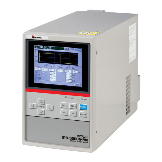
Thank you for purchasing the Miyachi Technos Inverter-type Welding Power Supply
IPB-5000A.
・ For correct use, read this operation manual carefully.
・ After reading, save it in a proper place where you can easily access to.
INVERTER-TYPE WELDING POWER SUPPLY
IPB-5000A-
OPERATION MANUAL
CURSOR
IP B - 50 0 0 A
START
POWER
WELD
MENU
RESET
-
+
ENTER
WELDING POWER SUPPLY
00-00
00-01
I07M0756E-01
Advertisement
Table of Contents

Related Manuals for Miyachi IPB-5000A-00-00


Summary of Contents for Miyachi IPB-5000A-00-00
- Page 1 + ENTER WELDING POWER SUPPLY Thank you for purchasing the Miyachi Technos Inverter-type Welding Power Supply IPB-5000A. ・ For correct use, read this operation manual carefully. ・ After reading, save it in a proper place where you can easily access to.
-
Page 2: Table Of Contents
IPB-5000A Table of Contents 1. Special Precautions ·········································································································1-1 (1) Safety Precautions ······································································································· 1-1 (2) Precautions for Handling······························································································ 1-4 (3) Warning Labels for Safety···························································································· 1-5 2. Features ···························································································································· 2-1 3. Packaging ························································································································· 3-1 4. Name and Functions of Each Section ············································································ 4-1 (1) Front Panel ··················································································································... - Page 3 IPB-5000A Table of Contents (Continued) 9. Time Chart························································································································· 9-1 (1) Fundamental Sequence ······························································································· 9-1 (2) Determination of Weld Schedule ················································································· 9-2 (3) Behavior of START SIG. HOLD ·················································································· 9-3 (4) Behavior of END SIG. TIME ························································································ 9-4 (5) Behavior of SOL1 and SOL2 ······················································································· 9-5 (6) “Error”...
-
Page 4: Special Precautions
Never disassemble, repair or modify the Power Supply. These actions can cause electric shock and fire. If any part needs to be checked or repaired, contact Miyachi Technos Corp. or your distributor for help. 1. Special Precautions... - Page 5 Do not tread on, twist or tense any cable. The power cable and connecting cables may be broken, and that can cause electric shock and fire. If any part needs to be repaired or replaced, consult Miyachi Technos Corp. or your distributor.
- Page 6 IPB-5000A CAUTION Apply the specified source voltage. Application of a voltage out of the specified range can cause fire and electric shock. Do not splash water on the equipment. Water splashed over the electric parts, can cause electric shock and short circuits.
-
Page 7: Precautions For Handling
IPB-5000A (2) Precautions for Handling Install the Power Supply on a firm and level surface. If it is used inclined or on its side, it may have a malfunction. Also, provide 10 cm clearance to the intake and exhaust for improving the effect of heat release (Refer to 5. -
Page 8: Warning Labels For Safety
IPB-5000A (3) Warning Labels for Safety The following warning labels are attached to the Power Supply for safe operation. The location of labels and the meaning of the symbols are as follows: DANGER WHEN INSPECTING INTERNAL, MAKE SURE TO TURN OFF MAIN CIRCUIT BREAKER AND WAIT FOR AT LEAST 5 MINUTES NOT TO GET AN ELECTRIC SHOCK. -
Page 9: Features
IPB-5000A 2. Features The Miyachi Technos IPB-5000A is an inverter-type power supply designed for spot welding and fusing. It is easy to move and install, as it is small in size and compact. In addition, the monitor function is provided which makes possible the judgment of defective or non-defective welding. -
Page 10: Packaging
IPB-5000A 3. Packaging Shipping Kit LIst Verify that contents of the container agree with the kit list. If you see any damage, please contact Miyachi Technos Corp. Packaged Kit Quantity IPB-5000A Operation Manual Cable Clamp (Large) for fixing I/O Cable... -
Page 11: Name And Functions Of Each Section
IPB-5000A 4. Name and Functions of Each Section (1) Front Panel Front Panel ① ③ ② ④ I PB - 5 0 0 0A START PO WE R ⑥ ⑦ WELD MENU RESET ⑤ CURSOR ⑧ - + ENTER ⑨ ⑩... - Page 12 IPB-5000A ⑤ CURSOR Key Moves the cursor upward/downward or to the right/left on Display Screen. ⑥ MENU Key Press MENU Key to display MENU Screen. ⑦ RESET Key Press RESET Key to reset the display of a trouble after removing the cause of the trouble when the trouble display is shown on Display Screen.
-
Page 13: Rear Panel
Pulling up the Lever supplies power; pushing down disconnects power supply. ④ Welding Transformer I/O Signal Connector Used for connecting [SENS] cable of welding transformer manufactured by Miyachi Technos Corp. ⑤ Terminal block for Welding Power Output Used for connecting to the input of welding transformer. -
Page 14: Installation And Connection
IPB-5000A 5. Installation and Connection (1) Installation When planning for the installation, allow at least the figured clearance on each side from the wall, as referred to the figures below, for improving the effect of heat release. Allow at least 10cm or more from the end of the Wiring Outlet projected at the Output Terminal Cover in the rear potion of IPB-5000A. -
Page 15: Connection
IPB-5000A (2) Connection 5000A Front Panel Welding Head Earth Leakage Secondary Breaker Cable I P B- 50 00 A START POWER WELD MENU RESET CURSOR - + ENTER *2 Voltage Detecting Cable Welding Transformer W EL DIN G P OW ER SUP PL Y MI YA CH I TE CH NO S C OR P. - Page 16 CAUTION If the connection is done as the figure ① below in the case of 400V System, it may damage IPB-5000A or Welding Transformer. ① IPB-5000A-00-00 for use ② IPB-5000A-00-01 for use (200V System Power Supply) (400V System Power Supply)
- Page 17 IPB-5000A (3) Connecting Voltage Detecting Cable Connect the Voltage Detecting Cable in the case of using Constant Voltage Control, Constant Current/Constant Voltage Combination Control and Constant Power Control. (4) Connecting a power supply Connect Input Cable from Breaker for Welding Power Input (See 4.(2)②) in the rear panel of IPB-5000A to Earth Leakage Breaker.
-
Page 18: Description Of Display Screens
IPB-5000A 6. Description of Display Screens (1) Operation Flow An example of the operation for the use of Welding Power Supply is shown as follows: 1. Start up IPB-5000A 2. Press MENU Key in the front panel to display MENU Screen 3. -
Page 19: Menu Screen
IPB-5000A (2) MENU Screen Setting of Values Move the cursor ( ) to the number or ON (or OFF) to be set or changed and press +/- key to complete such setting as input of a number or change of ON/OFF. - Page 20 IPB-5000A ① Constant Current Control ② Constant Voltage Control ③ Constant Current/Constant Voltage Combination Control ④ Constant Power Control 6. Discription of Display Screens...
- Page 21 IPB-5000A As the following, each item of (a) to (h) put on the Control Screens, ①,② and ④ is described. (a) SCHEDULE # It denotes No. of weld SCHEDULE. 127 weld schedules as SCHEDULE#1 to #127 can be set on IPB-5000A. (b) TIME Time period of each movement in welding is set at the dimension of ms.
-
Page 22: Monitor Screen
IPB-5000A (4) MONITOR Screen In this screen, you can confirm the working condition during welding. The monitored data, that is, Current, Voltage, Power and Resistance in every schedule are displayed. Current is indicated in yellow solid line, Voltage is cyan, Power is green and Resistance is magenta. - Page 23 IPB-5000A (d) PEAK/RMS Switch between PEAK and RMS of Voltage. The screen on a previous page shows RMS. (e) POWER The waveform of Power can be displayed. (f) RESIST The waveform of Resistance can be displayed. (g) TOTAL COUNT The mode of a counter can be displayed. For details, see (8)④(c)COUNTER. (h) Pulse Width Monitor The mean value of pulse widths of the supplied pulse current is displayed in the percentage to 100% of the pulse width at the full wave.
-
Page 24: Comparator Screen
IPB-5000A (5) COMPARATOR Screen Set the upper and lower criterion of Current, Voltage, Power and Resistance for judging “Good” or “No Good” weld. If the monitored value is inside the criterion, Good is determined. If it is outside, No Good is determined. If the monitored value equals to the criterion, Good is determined. -
Page 25: Envelope Screen
IPB-5000A (6) ENVELOPE Screen Here, the envelope waveform is prepared. The function of Envelope is to draw a waveform (here, calling Envelope Waveform) having allowable criteria based on a standard waveform (an average actual weld waveform) and compare a monitored actual weld waveform with the Envelope Waveform in order to judge “Good”... - Page 26 IPB-5000A (e) ON/OFF Set the activation or inactivation of the function. ON------------ Envelope function works OFF ---------- Envelope function does not work (f) NEW Press the button to select a standard waveform. (g) EDIT Press the button to change INTERVAL, OFFSET or ON/OFF one another. (h) COPY Makes a copy of the data of Envelope Waveform.
- Page 27 IPB-5000A ② Select NEW Button to draw a standard waveform. ③ Select MON Button to draw a standard waveform from a monitored waveform. ④ Select CURR Button to draw the standard waveform of a current waveform. Select each button on the right of CURR button for Voltage, Power and Resistance.
- Page 28 IPB-5000A ⑥ Set INTERVAL, OFFSET and ON/OFF press RETURN Button. ⑦ Select WRITE Button for storing the setting. ⑧ Here, in this step, Envelope Waveform has been set. Envelope Waveform When displaying the monitored screen, Envelope Waveform will appear. 6. Discription of Display Screens 6-11...
-
Page 29: Precheck Screen
IPB-5000A (7) PRECHECK Screen Set the period of a weld time and a control voltage for Resistance PRECHECK in this screen. The function of Resistance PRECHECK is to flow lower current in Constant Voltage Control method just before supplying the weld current and see if work pieces to be welded are correctly positioned by the use of the measured value of current then. -
Page 30: Status Screen
IPB-5000A (8) STATUS Screen Change the initial setting of IPB-5000A here in this screen. According to customer’s preference, precise setting can be obtained. ① STATUS (1/2) Screen (a) WELD TRANS Set a transformer. Select it among ITE-142A6, ITD-360A6 and ITB-780A6. (b) CONTROL Set a weld control method. -
Page 31: ② Status (2/2) Screen
IPB-5000A (e) SCHEDULE# Fixes the method of how to select a schedule. EXT. (NP): Select a schedule by closing a schedule-selecting terminal on Rear Panel EXT. (P) : Select a schedule by closing a schedule-selecting terminal and a parity terminal on Rear Panel. PANEL : Select a schedule on Front Panel. - Page 32 IPB-5000A (b) TRANS INTERVAL It is a preparatory setting function. Do not change it. (c) COMM MODE It is a preparatory setting function. Do not change it. (d) COMM UNIT# It is a preparatory setting function. Do not change it. (e) COMM SPEED It is a preparatory setting function.
-
Page 33: ③ Error Setting Screen
IPB-5000A ③ ERROR SETTING Screen The signals output at the occurrence of an error (NG Signal/Caution Signal) can be set item by item. (a) OFF/ON OFF : NG Signal is output. The input of Start Signal is not accepted at the occurrence of Caution Signal is output. - Page 34 IPB-5000A (c) COUNTER Set the mode of Counter. TOTAL Count-up (increment of +1) is done despite the result of the judgment in monitoring when the current is supplied. Judgment in Monitor Counting Manner GOOD Count-up CAUTION Count-up Count-up GOOD Count-up is done if the judgment is GOOD in current-supplied monitoring.
-
Page 35: Basic Operation
IPB-5000A 7. Basic Operation The example of a basic operation is described, using a transformer ITB-780A6 and a control method of Constant Current Control. (1) Connect correctly Welding Transformer ITB-780A6 and peripheral equipments to IPB-5000A, referring to the connection way (5.Installation and Connection). (2) Turn on the Breaker. - Page 36 IPB-5000A Item Value Item Value SCHEDULE# UP SLOPE at WE1 400ms UP SLOPE at WE2 20ms DOWN SLOPE at WE1 COOL DOWN SLOPE at WE2 20ms CURR at WE1 HOLD 10ms CURR at WE2 (6) For the test of welding, press MENU Front Panel, select...
- Page 37 IPB-5000A (10) Set ON (Closed circuit) to 2ND STAGE Start Input to begin testing the weld. The squeeze signal is output, and then the weld head begins to squeeze for the weld. As the figure on the right is displayed, check that the weld schedule is correctly set.
-
Page 38: External Interface
IPB-5000A 8. External Interface (1) Connection Diagram for External Input/Output Signals ① When contacts on PLC are used as input signal 24VDC INT.24V EXT.COM STOP SCH 1 SCH 2 SCH 4 SCH 8 SCH16 SCH32 SCH64 PARITY(WE1 STOP) WELD ON/OFF ERROR RESET COUNT RESET W.INTERRUPT... -
Page 39: ② When Npn Transistor (Sink Type) On Plc Is Used As Input Signal
IPB-5000A ② When NPN transistor (sink type) on PLC is used as input signal 24VDC INT.24V EXT.COM STOP P L C SCH 1 SCH 2 SCH 4 SCH 8 SCH16 SCH32 SCH64 PARITY(WE1 STOP) WELD ON/OFF ERROR RESET COUNT RESET W.INTERRUPT PRG PROTECT GOOD... -
Page 40: ③ When Pnp Transistor (Source Type) On Plc Is Used As Input Signal
IPB-5000A ③ When PNP transistor (source type) on PLC is used as input signal P L C 24VDC INT.24V 24VDC EXT.COM STOP SCH 1 SCH 2 SCH 4 SCH 8 SCH16 SCH32 SCH64 PARITY(WE1 STOP) WELD ON/OFF ERROR RESET COUNT RESET W.INTERRUPT PRG PROTECT GOOD... -
Page 41: ④ When Solenoid Valves Are Activated By The Use Of An External Power Supply
IPB-5000A ④ When solenoid valves are activated by the use of an external power supply 24VDC 120VAC 24VDC SOL POWER SOL 1 SOL 2 SOL COM ⑤ When solenoid valves are activated by the use of an internal power supply 24VDC INT.24V SOL POWER... - Page 42 IPB-5000A Pin No. Description 1ST STAGE Intput Terminal. Closing of this Pin makes SOL1 Terminal of Pin 32 close. As the current-supplying sequence does not start, the adjustment or check of a squeeze location can be done. When closing 2ND STAGE Terminal at this location, the weld at the optimum squeeze location can be obtained.
- Page 43 IPB-5000A Pin No. Description COM Terminal. Internally connected to GND Chassis. GOOD Signal Output Terminal. If it is determined that the measured value is inside the range set in MONITOR Screen after a weld sequence has ended, the Pin keeps closed for the certain period.
- Page 44 IPB-5000A Pin No. Description COMMON Terminal for Output. Shared commonly for GOOD, NG, END, CAUTION, COUNT UP and READY. COMMON Terminal for Output. Shared commonly for GOOD, NG, END, CAUTION, COUNT UP and READY. POWER Input Terminal for activating a solenoid valve. Input the power of 120VAC, 24VDC or 24VAC.
-
Page 45: Schedule No. And Schedule Select Terminals
IPB-5000A (3) Schedule No. and Schedule Select Terminals Schedule No. : SCHEDULE# Blank: Open ●:Closed SCHEDULE# SCH 1 SCH 2 SCH 4 SCH 8 SCH16 SCH32 SCH64 PARITY ● ● ● ● ● ● ● ● ● ● ● ● ●... - Page 46 IPB-5000A Schedule No. : SCHEDULE# Blank: Open ●:Closed SCHEDULE# SCH 1 SCH 2 SCH 4 SCH 8 SCH16 SCH32 SCH64 PARITY ● ● ● ● ● ● ● ● ● ● ● ● ● ● ● ● ● ● ● ●...
- Page 47 IPB-5000A Schedule No. : SCHEDULE# Blank: Open ●:Closed SCHEDULE# SCH 1 SCH 2 SCH 4 SCH 8 SCH16 SCH32 SCH64 PARITY ● ● ● ● ● ● ● ● ● ● ● ● ● ● ● ● ● ● ● ●...
-
Page 48: Time Chart
IPB-5000A 9. Time Chart (1) Fundamental Sequence 2ND STAGE SOL2 Output Weld Current END Output GOOD Output NG Output CAUTION Output Symbol: SQ: Squeeze Time RC: Resistance Pre-check Time CP: Resistance Judgment Time (1ms) U1: Upslope 1 Time W1: 1st Weld Time D1: Downslope 1 Time CO: Cool Time U2: Upslope 2 Time... -
Page 49: Determination Of Weld Schedule
IPB-5000A (2) Determination of Weld Schedule Weld Schedule is determined after Chattering Prevention Time, “START SIG. TIME” elapses from the input of Start Signal. ( A ) ( B ) Period set at Period set at START SIG. TIME START SIG. TIME 2ND STAGE 2ND STAGE SCH1... -
Page 50: Behavior Of Start Sig. Hold
IPB-5000A (3) Behavior of START SIG. HOLD * NO HOLD Setting: If Start Signal is made open during the period from SQ to W2, a weld sequence is broken off on the way and results in E13: CYCLE ERROR. Even if Start Signal is made open during HO, the weld sequence goes to an end * WE HOLD Setting: After a beginning of W1, a weld sequence goes to an end even if Start Signal is made open. -
Page 51: Behavior Of End Sig. Time
IPB-5000A (4) Behavior of END SIG. TIME * HOLD: When 2ND STAGE Signal is closed for 10ms or less, END or GOOD Signal is output for 10ms. When 2ND STAGE Signal is closed for the longer period than 10ms, END or GOOD Signal is output for the closed period. * 10ms, 100ms: END or GOOD Signal is output for the set period regardless of the condition of 2ND STAGE Signal. -
Page 52: Behavior Of Sol1 And Sol2
IPB-5000A (5) Behavior of SOL1 and SOL2 SOL1 Output works by the Input of 1ST STAGE. When 1ST STAGE Input is open, SOL1 Output also becomes open if it is before the start of a weld sequence. After the start of a sequence, even if 1ST STAGE Input is open, SOL1 Output keeps closed until the sequence comes to an end. -
Page 53: Error" Or "Caution" In Precheck
IPB-5000A (6) “Error” or “Caution” in PRECHECK A sample weld sequence is shown, which represents the occasion where, when the function of PRECHECK Current Supply is used, a current goes out of the range between the upper and lower limit set in PRECHECK Screen and an error signal of “NG”... -
Page 54: At Occurrence Of "Error" Or "Caution
IPB-5000A (7) At Occurrence of “Error” or “Caution” A sample weld sequence is shown, which represents the occasion where NG or CAUTION is produced while current is supplied. 2ND STAGE SOL2 Output Weld Current Sequence is not performed after NG or Caution is produced. NG Output NG OUTPUT: NORMALLY OPEN... -
Page 55: Specifications
IPB-5000A 10. Specifications (1) Specifications Model name IPB-5000A-00-00 IPB-5000A-00-01 Three-phase, 200 to 240VAC Three-phase, 380 to 480VAC (50 Hz / 60 Hz) (50 Hz / 60 Hz) (Voltage cannot be selected. (Voltage cannot be selected. Power Supply Fixed to a customer-... - Page 56 IPB-5000A Model name IPB-5000A-00-00 IPB-5000A-00-01 Current Upper/Lower Limit : 0.00 to 9.99kA (0.01kA ea.) Voltage Upper/Lower Limit : 0.00 to 9.99V (0.01V ea.) Monitor Setting Power Upper/Lower Limit : 00.0 to 20.0kW (0.1kW ea.) Range Resistance Upper/Lower Limit : 00.0 to 99.9mΩ(0.1mΩ ea.) Set at COUNTER.
-
Page 57: Optional Items (Separately Sold)
IPB-5000A Model name IPB-5000A-00-00 IPB-5000A-00-01 Starting Time of Set at NO CURR MONITOR START. detecting No Current 00 to 10ms (Starts to detect No Current or Voltage after the or No Voltage set period) Pulse Monitoring Set at PW MONITOR START. -
Page 58: ② Output Cables Pk-01856
IPB-5000A ② Output Cables PK-01856-□□□ If a customer procures the cable by oneself, prepare it in accordance with the following right-hand specifications. Branch Length Specifications of Standard Cable Type -002 Rated Voltage 600VAC min. Standard -005 Section Area min. -010 No. -
Page 59: Error Codes
E-01 SYSTEM ERROR is displayed on control system of E-01 ERROR again, repair is required. IPB-5000A. Contact Miyachi Technos Corp. Check all set data. The following is assumed to cause the data stored in memory to be corrupted. *Strong power noise or electrostatic noise... - Page 60 IPB-5000A Error Contents Cause Countermeasures Code Short-circuit wire is cut Connect Pin 1 to Pin 3 on rear terminal E-07 ABORT between Pin 1 and Pin 3 strip. STOP on rear panel. *Check the pressing force, electrode contact and wire connection of weld head.
- Page 61 IPB-5000A Error Contents Cause Countermeasures Code Current is out of range between upper limit Check weld pickup (contamination) of PRECHECK and lower limit set E-15 electrodes, contact of electrodes and work ERROR PRECHECK Screen pieces. when PRECHECK Current Supply is used. Measured weld current CURR is out of upper limit set...
-
Page 62: Outline Drawing
IPB-5000A 12. Outline Drawing Dimensions in mm 12. Outline Drawing 12-1... -
Page 63: Schedule Data Table
IPB-5000A 13. Schedule Data Table (1) Weld Schedule Setting 13. Schedule Data Table 13-1... - Page 64 IPB-5000A 13. Schedule Data Table 13-2...
- Page 65 IPB-5000A 13. Schedule Data Table 13-3...
- Page 66 IPB-5000A 13. Schedule Data Table 13-4...
- Page 67 IPB-5000A 13. Schedule Data Table 13-5...
- Page 68 IPB-5000A 13. Schedule Data Table 13-6...
- Page 69 IPB-5000A 13. Schedule Data Table 13-7...
-
Page 70: Precheck Setting
IPB-5000A (2) PRECHECK Setting CURR CURR CURR CURR TIME VOLT TIME VOLT SCH1 SCH28 SCH2 SCH29 SCH3 SCH30 SCH4 SCH31 SCH5 SCH32 SCH6 SCH33 SCH7 SCH34 SCH8 SCH35 SCH9 SCH36 SCH10 SCH37 SCH11 SCH38 SCH12 SCH39 SCH13 SCH40 SCH14 SCH41 SCH15 SCH42 SCH16... - Page 71 IPB-5000A CURR CURR CURR CURR TIME VOLT TIME VOLT SCH55 SCH84 SCH56 SCH85 SCH57 SCH86 SCH58 SCH87 SCH59 SCH88 SCH60 SCH89 SCH61 SCH90 SCH62 SCH91 SCH63 SCH92 SCH64 SCH93 SCH65 SCH94 SCH66 SCH95 SCH67 SCH96 SCH68 SCH97 SCH69 SCH98 SCH70 SCH99 SCH71 SCH100...
- Page 72 IPB-5000A CURR CURR CURR CURR TIME VOLT TIME VOLT SCH113 SCH121 SCH114 SCH122 SCH115 SCH123 SCH116 SCH124 SCH117 SCH125 SCH118 SCH126 SCH119 SCH127 SCH120 13. Schedule Data Table 13-10...
-
Page 73: Monitor Setting
IPB-5000A (3) Monitor Setting 13. Schedule Data Table 13-11... - Page 74 IPB-5000A 13. Schedule Data Table 13-12...
- Page 75 IPB-5000A 13. Schedule Data Table 13-13...
- Page 76 IPB-5000A 13. Schedule Data Table 13-14...
- Page 77 IPB-5000A 13. Schedule Data Table 13-15...
- Page 78 IPB-5000A 13. Schedule Data Table 13-16...
- Page 79 IPB-5000A 13. Schedule Data Table 13-17...
-
Page 80: Status Setting
IPB-5000A (4) Status Setting STATUS WELD TRANS CONTROL START SIG.TIME START SIG.HOLD SCHEDULE# END SIG.TIME MONITOR MODE PARITY/WE1STOP LCD CONTRAST TRANS SCAN MODE TRANS INTERVAL COMM MODE COMM UNIT# COMM SPEED NO CURR MONITOR START PW MONITOR START NG OUTPUT READY OUTPUT ERROR SETTING :NO CURRENT... - Page 81 (2) When a Miyachi Technos Corporation product is being set up for operation at an overseas facility under the presence of a serviceman of Miyachi Technos Corporation or overseas Miyachi affiliated companies, Miyachi Technos Corporation will warrant the product for the warranty period under the described conditions below.
- Page 82 Corporation will send it to the customer’s designated location and charge the customer for all shipping costs. (3) When a Miyachi Technos Corporation product is being set up for operation at overseas facility without the presence of a serviceman of Miyachi Technos Corporation or overseas Miyachi affiliated companies, the warranty expires in principle within the warranty period of one (1) year.
- Page 83 (6) Exchange of consumable items 5. Responsibility of our Company Miyachi Technos Corporation is responsible for restoring the status of its products due to failure by repair in case of defect. Miyachi Technos Corporation is not liable for any direct or indirect damage arising from any defect or use of its products.
- Page 84 (7) years after production is discontinued. In the case of a computer and its peripheral equipment, Miyachi Technos Corporation will stock the parts and units for repair for at least six (6) years in principle after production is discontinued.
- Page 85 Attention Do not duplicate, partially or entirely, the operation manual. ・ Miyachi Technos Corporation reserves the right to change the content of the operation ・ manual at any time without notice. Although Miyachi Technos Corporation created the operation manual with making ・...
- Page 86 Miyachi Korea Corp. D-510, Pundang Techno-Park, 151, Yatap-Dong, Pundang-Gu, Songnam-city, Kyunggi-Do, Korea TEL +82-342-707-5855 FAX +82-342-707-5857 Miyachi Trading (Shanghai) Co. Ltd. 6F, Building 64, No.421 Hong Cao Road Shanghai, 200233 China TEL +86-21-6485-9595 FAX +86-21-6485-9797 Unitek Miyachi Corp. 1820 South Myrtle Ave., Monrovia, CA 91017-7133 U. S. A.
Need help?
Do you have a question about the IPB-5000A-00-00 and is the answer not in the manual?
Questions and answers