Table of Contents
Advertisement
Quick Links
Advertisement
Table of Contents

Related Manuals for Hussmann VR3-M/F-EP


Summary of Contents for Hussmann VR3-M/F-EP
- Page 1 VR3-M/F-EP,VR3HV-MF-EP MEAT/FISH REMOTE INSTALLATION & OPERATION GUIDE...
-
Page 2: Table Of Contents
Table of Contents User Information Case Sections Start Up Installation Load Limit Receiving Case Basic Operation Snapping Chalk Lines Merchandising Requirements Placement Merchandising DON’TS Lifting and Transport Instructions Maintenance VR3 M/F Drain Location Case Cleaning Lower Body Panel Install Exterior Surfaces Rear Body Panel Install Cleaning Bumpers Levelling Adjustment... - Page 3 Shortages: Check your shipment for any possible shortages of material (See Parts List page 11). If a shortage should exist and is found to be the responsibility of Hussmann Chino, notify Hussmann Chino. If such a shortage involves the carrier, notify the carrier immediately, and request an inspection. Hussmann Chino will acknowledge shortages within ten days from receipt of equipment.
-
Page 4: Case Sections
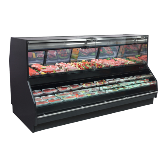
Case Sections VR3-M/F-EP +2 VR3-M/F-EP +4 Vertical Glass Meat Vertical Glass Meat VR3-M/F-EP Vertical Glass Meat Standard Service Dome, Multi Deck Self Service +2" height Standard Service Dome, Multi Deck Self Service +4" height Standard Service Dome, Multi Deck Self Service... -
Page 5: Installation
(Not actual case) Receiving Case Upon receiving your new Hussmann Case all equipment should be thoroughly examined for shipping damage before and during unloading. This equipment has been carefully inspected at our factory. Any claim for loss or damage must be made to the carrier. -
Page 6: Placement
Installation (cont’d) Placement Remove screws as well as fastened plates bolted to each Important: See lifting instructions to properly lift case when 2x4 board at each base leg. being placed on dollies or permanent location. (See page 7 for Lifting Instructions.) Leave all hardware and fittings in place until case is located at or near its preferred location. -
Page 7: Lifting And Transport Instructions
Installation (cont’d) Lifting and Transport Instructions 1. The VR3 can be lifted by a forklift at typical lifting points. 2. Ensure lower body panels are removed before lifting with a forklift. Serious damage will occur if the body panels are not removed. 3. -
Page 8: Lower Body Panel Install
Installation (cont’d) Lower Body Panel Install Rear Body Panel Install No tools will be needed to install body panels. 1. Align clips of rear panel to Base Legs of case 2. Secure top and bottom clips of rear panel to Base Legs as shown below. -
Page 9: Levelling Adjustment
Installation (cont’d) Levelling Adjustment Position the case at the highest point. Set a long magnetized level (4ft [1220 mm] or more) on either underneath the deck or on top of the case. Ensure to level case from front to back and side to side. Level (4 ft[1220mm]) Level... -
Page 10: Installation (Joint Checksheet)
Installation (Joint Checksheet) INSPECTOR _________________ VR3HV/VR3/ JOINT CHECKSHEET SALES ORDER # _____________ *SEE INSTALLATION GUIDE EXT COLOR _________________ INDICATES CASE BOLTING/ALIGNMENT POINT INT FINISH __SS__/__BLACK___ ITEM PART # GRAPHIC □ JQRP* 2H20345(STAINLESS) JQR* FRONT BODY PANEL TRIM □ 2H20345 (EXT COLOR) □... -
Page 11: Arm Adjustment (Hv Only)
Installation (cont’d) IMPORTANT: Preloading the Canopy Arm Arm Adjustment (HV Only) STEP1. Ensure case is level to the ground.Check level at After reaching level (on Level 2) turn the connectors two the bulkhead as shown(LEVEL1). full rotations clockwise to raise the canopy. STEP2. -
Page 12: Arm Adjustment(Non-Hv)
Installation (cont’d) STEP5. Locate and loosen lock bolts under each canopy Arm Adjustment(NON-HV) arm. STEP1. Ensure case is level to the ground.Check level as shown(pg 9). STEP2. Remove service section deck pans and arm drain/ pipe covers to avoid damaging parts during adjust LOCK BOLT ment. - Page 13 Installation (cont’d) STEP6. Shim each arm accordingly to bring canopy arms Once proper heght is acheived, tighten the lock-bolts to level. Once proper heght is acheived, tighten and complete steps in reverse order to assemble case. the lock-bolts and complete steps in reverse order Glass must be parallel to ledge when viewed from front.
-
Page 14: Glass Adjustment
Installation (cont’d) Glass Adjustment Follow these steps accordingly to properly and safely adjust the positioning of the front glass. Before adjusting glass LOWER HINGE Set, Level, and Bolt together all cases STOP HINGE ASSEMBLY Double check leveling for all cases COVER (GLASS NOT SHOW... -
Page 15: Setting And Joining
Installation (cont’d) Setting and Joining 1. Using case blueprints, measure off and mark on the The sectional construction of these models enable them floor the exact dimensions of where the cases will sit. to be joined in line to give the effect of one continuous Snap chalk line for front and back positions of base rail or display. pedestal. Mark the location of each joint front and back. Find the highest point throughout the lineup. FLOORS Bolting locations which join like cases together are ARE NORMALLY NOT LEVEL! Determine the highest displayed below. - Page 16 Installation (cont’d) 3. Set second case within one foot (1’) of the first case. 5. Apply liberal bead of case joint sealant (butyl) to Keep the supports along the length of the case and far first case. Sealant area is shown using a striped line in end of case. Level case to the first using the instructions in illustration in page 16. Apply heavy amount to cover entire step one. shaded area. 4.
- Page 17 Installation (cont’d) 7. To compress butyl at joint, use two Jurgenson wood clamps. Make sure case is level from front to back and side to side on inside bulkheads at joint. 8. Attach sections together via the bolts pictured in the illustration below.
-
Page 18: Refrigeration
In the case pressure was not at factory already. Seal both the inside and outside. We maintained contact your Hussmann Service Tech for recommend using an expanding polyurethane foam further assistance. -
Page 19: Piping Diagram (General)
Refrigeration (cont’d) Piping Diagram (General) -
Page 20: Refrigeration Components
Refrigeration (cont’d) Refrigeration Components See demonstrations below for detailed overview of the VR3HV-M/F C/S-EP piping components. Note: Refrigeration components have been fitted with a component tray for ease in use of cleaning and maintenance under the deck pans. SOLENOID HAND VALVE FILTER DRIER... -
Page 21: Spiral Coil And Gravity Coil
Refrigeration (cont’d) Spiral Coil and Gravity Coil Gravity Coil Spiral Coil... -
Page 22: Refrigeration Spec Sheets
Refrigeration Spec Sheets VERTICAL MEAT SERVICE - SELF SERVICE REVISION DATE 9/11/2020 HUSSMANN - VR3M/F-EP SH, +2H, & +4H OPTIONS (CHINO) REFRIGERATION DATA: EST. 20°F GLYCOL CAPACITY TOP/FRONT TEMPERATURE (ºF) VELOCITY REFG. 6° RISE *** (BTU/HR/FT) CASE TOP/FRONT CHRG. REAR... - Page 23 Refrigeration Spec Sheets(Cont’d) HIGH VOLUME MEAT/FISH SERVICE - SELF SERVICE REVISION DATE 9/11/2020 HUSSMANN - VR3HV-M/F-EP SH, +2H, & +4H OPTIONS (CHINO) INSERTI ON 3 7/8" POINT SUPPORT LE GS REAR 56" 17 3/8" CLOSE-OFF Upper Drain 53" 50 3/8"...
-
Page 24: Electrical
Electrical Field Wiring Merchandiser Electrical Data Field wiring must be sized for component amperes Technical data sheets are shipped with this manual. The stamped on the serial plate (refer to pg 18 for location). data sheets provide merchandiser electrical data. Refer to Actual ampere draw may be less than specified. -
Page 25: Remove Rear Raceway
Electrical Conduit containing all necessary electrical components including but not limited to Digital T-Stats are located behind the rear raceway covers of the merchandiser. Wiring Diagram Index Model Tier Description Size Diagram # VR3-M/F-EP-4-R 4’ 3014732 VR3-M/F-EP-6-R 6’ 3014731 VR3-M/F VR3-M/F-EP-8-R 8’ 3014730 VR3-M/F-EP-12-R 12’... -
Page 26: Electrical Wiring Diagram
Electrical Wiring Diagram... - Page 27 Electrical Wiring Diagram (Cont’d)
- Page 28 Electrical Wiring Diagram (Cont’d)
- Page 29 Electrical Wiring Diagram (Cont’d)
- Page 30 Electrical Wiring Diagram (Cont’d)
- Page 31 Electrical Wiring Diagram (Cont’d)
- Page 32 Electrical Wiring Diagram (Cont’d)
- Page 33 Electrical Wiring Diagram (Cont’d)
- Page 34 Electrical Wiring Diagram (Cont’d)
-
Page 35: User Information
This includes, but is not limited to, such items as Basic Operation The VR3-M/F-EP series case cools meat/fish in two ways: doors, lights, fans, heaters, and thermostats. 1. The Spiral Deck Coil under the display deck cools the meat/fish product by means of contact conduction. -
Page 36: Merchandising Requirements
User Information (cont’d) Merchandising Requirements Use a consistent display strategy in each case . Rotate product every several hours. Bottom layer should Hussmann recommends the use of flat bottomed be rotated to the top and flipped. This ensures even aluminum or high density plastic trays as the ideal cooling, dehydration and color maintenance. merchandising display method. -
Page 37: Merchandising Don'ts
Refrain from using any display ware which prevents direct contact between the display ware bottom and the cooled display pans. Any air space between the Hussmann opticold deck pans, the display ware or the product will adversely affect case optional performance and cause elevated product temperature and refrigerated or early product loss. -
Page 38: Maintenance
Maintenance Case Cleaning Long life and satisfactory performance of any equipment Interior Surfaces are dependent upon the care it receives. To insure long The interior surfaces may be cleaned with most domestic life, proper sanitation and minimum maintenance costs, detergents, ammonia based cleaners and sanitizing the merchandiser should be thoroughly cleaned, all debris solutions that do not contain chloride with no harm to the removed and interiors washed down, weekly. -
Page 39: Prop 65 (Ca Only)
After cleaning has been completed, remember to restore power back to merchandiser. This warning does not mean that Hussmann products will cause cancer or reproductive harm, or is in violation of any product-safety standards or requirements. As clari ed by the California State government, Proposition 65 can be considered more of a ‘right to... -
Page 40: Troubleshooting
Troubleshooting Problem Possible Cause Possible Solution Product too cold Spiral Deck Coil (SDC) is Probe the deck with the product in place. If the deck is less and/ or freezing too cold. than 29°F increase the SDC thermostatic SP incrementally. Allow approximately 60 minutes or stable temperatures for system to react then recheck temperatures. - Page 41 High recommended Product is displayed in Use containers with full length, flat bottoms. Refer to containers that impede MERCHANDIZING RECOMMENDATIONS (page 29) section the conduction cooling for further information. from the SDC Incorrect replacement Use only Hussmann genuine replacement parts or equivalent. lighting is adding too much heat...
- Page 42 Troubleshooting Cont’d Problem Possible Cause Possible Solution Case temperature is Ambient conditions may Check case position in store. Is the case located near an too warm. be affecting the case open door, window, electric fan or air conditioning vent that operation. may cause air currents? Case must be located minimum 15 Ft away from doors or windows.
- Page 43 Troubleshooting Cont’d Problem Possible Cause Possible Solution Lights do not come LED Driver /light wiring. Check electrical connections. See Electrical Section and check wiring diagram. LED Driver needs to be Case should be serviced by a qualified service technician. replaced. See Electrical Section. LED Light needs to be Case should be serviced by a qualified service technician.
- Page 44 To obtain warranty information or other support, contact your Hussmann representative. Please include the model and serial number of the product. Hussmann Warranty / Technical Assistance (800) 592-2060 Hussmann Corporation, Corporate Headquarters: Bridgeton, Missouri 63044 2014...
Need help?
Do you have a question about the VR3-M/F-EP and is the answer not in the manual?
Questions and answers