
Related Manuals for Condair UDC


Summary of Contents for Condair UDC
- Page 1 INSTALLATION AND OPERATION MANUAL Condair sensor and controller range Humidification and Evaporative Cooling...
- Page 2 Condair Group AG, except to the extent required for installation or maintenance of recipient's equipment. Liability Notice Condair Group AG does not accept any liability due to incorrect installation or operation of the equipment or due to the use of parts/components/equipment that are not authorised by Condair Group AG. Copyright Notice ©...
-
Page 3: Table Of Contents
Condair CDC, CDC-NA, CDC-ST and CDC-SL Functional description Safety Delivery Mounting location Installation Product specifications Wiring diagrams/Configuration Connecting the CDC, CDC-NA, CDC-ST or CDC-SL to Condair units Condair CRC and CRC-NA Functional description Safety Delivery Mounting location Installation Product specifications... - Page 4 Condair CHD, CHD-S and CHD-NA Functional description Safety Delivery Mounting location Installation Product specifications Connecting the CHD, CHD-NA or CHD-S to Condair units Operation of the CHD, CHD-S and CHD-NA Condair CHR and CHR-NA Functional description Safety Delivery Mounting location...
- Page 5 Functional description 10.2 Safety 10.3 Delivery 10.4 Mounting location 10.5 Installation 10.6 Product specifications 10.7 Connecting the CDA or CDA-S to Condair units Condair APS and APS-NA 11.1 Functional description 11.2 Safety 11.3 Delivery 11.4 Mounting location 11.5 Installation 11.6 Product specifications 11.7...
-
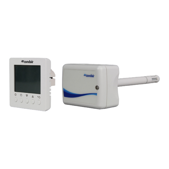
Page 6: Condair Udc
The universal controller Condair UDC is a programmable controller and sensor for duct installation. It has 2 control loops with 2 PI sequences each. The Condair UDC has an RS485 communication interface which enables programming with a PC and the Easyset program. The Condair UDC uses the universal X2 operating system. -
Page 7: Mounting Location
The Condair UDC is installed directly on the duct. – Mounting in the extract air duct (recommended): Mount the UDC in the extract air duct close to the air outlet of the room but downstream from a extract air fan if one is present. –... -
Page 8: Product Specifications
Max. rH tolerance at 25 °C (77°F) Hysteresis ± 1% Repeatability ± 0.1% Stability < 0.5% / year Signal outputs Analog Outputs AO1, AO2 Analog signal DC 0-10V or 0…20mA Resolution 39 mV, 0.078 mA Maximum load Voltage: ≥1kΩ, Current: ≤250Ω Condair UDC... - Page 9 Degree of protection IP30 according to 60 529 Pollution class II (EN 60 730-1) Protection class III (IEC 60536) Overvoltage category I (EN 60 730-1) General Housing material PC and ABS Weight (including packaging) 380g (13.4oz) Condair UDC...
-
Page 10: Wiring Diagram/Configuration
Sec. Sec. Signal type Signal range JP1/JP2 0...10 V 0...20 mA JP4 = OPxx-VC Termination AES4 AEX2 2...10 V 120Ω 4...20 mA Data AEC-PM2 Power RT/DI OPxx-VC NO DO1 NC OP1 OP2 OP3 OP4 24 VAC/DC Temperature Humidity Condair UDC... -
Page 11: Operation Of The Udc
Operation of the UDC 1.8.1 Display and operating elements Control loop indication Actual value / Parameter description <Up> button Set point value / Parameter description <On/Off> button <Enter> button <Down> button Operating status Functions Active digital outputs Level indicator Symbols Occupied: (Comfort) All control functions operating per set points. - Page 12 Err4: Configuration error: An assigned input is not activated or has failed. Check all settings and ensure that all inputs used are activated and functional. Err5: Copy error: Communication error with external memory AEC-PM1 or AEC-PM2. Err6: Copy error: Checksums of the data record are incorrect. The data record is invalid. Condair UDC...
- Page 13 Day of the month flashes: <Up>/<Down> button for adjustment, <Enter> button to save setting. • Month flashes: <Up>/<Down> button for adjustment, <Enter> button to save setting. • Year flashes: <Up>/<Down> button for adjustment, <Enter> button to save setting. 2021 1.3 Press <On/Off> button (1x) to return. Condair UDC...
- Page 14 2.2, 2.3 and 3.2 4.2 Press <Up> button. PRO and SEL are displayed. 4.3 Press <Enter> button while PRO-ON or OFF is displayed: Press <Up> or <Down> button to select between programs 1 - 12 (see point 3.3). Condair UDC...
- Page 15 After pressing the <Enter> button, you have returned to point 3.2. Now you can start creating the weekly schedules for programs 2 - 12. Appropriate times, weekdays as well as control loops or outputs can then be specified. Condair UDC...
- Page 16 Select the last month of the holiday schedule, where "1" stands for January and 01.01 "12" for December. The month flashes. Press the <Up> or <Down> button to select the month. Pr01 Press the <Enter> button to complete the operation. The 4 bars indicate that step 4 is complete. Condair UDC...
- Page 17 After pressing the <Enter> button, you have returned to point 3.2. Now you can start creating the weekly schedules for programs 2 - 12. Appropriate times, weekdays as well as control loops or outputs can then be specified. Condair UDC...
-
Page 18: Condair Cdc, Cdc-Na, Cdc-St And Cdc-Sl
CDC-ST / CDC-SL Functional description The Condair CDC, CDC-NA, CDC-ST or CDC-SL serve for the humidity measurement in air ducts. For the humidity measurement a capacitive humidity sensor is used. The microprocessor samples the humidity once per second. It calculates an averaging signal over a preset number of seconds and generates the output signal. -
Page 19: Mounting Location
– Mounting in the extract air duct (recommended): Mount the CDC, Condair CDC-ST or Condair CDC-SL in the extract air duct close to the air outlet of the room but downstream from a extract air fan if one is present. -
Page 20: Product Specifications
< 0.03 °C / year Signal outputs Analog Outputs Analog signal CDC and CDC-ST 0-10V or 0…20mA / 2-10V or 4…20mA CDC-SL and CDC-NA 2-10V fixed Resolution 10 Bit, 9.7 mV, 0.019.5 mA Maximum load 20 mA, 500Ω Condair CDC, CDC-NA, CDC-ST and CDC-SL... - Page 21 PC and ABS Filter material PTFE coated 1μm pores Weight CDC (including packaging) 270 g (9.5 oz) 2.6.2 Dimensions 2.6.2.1 Dimensions Condair CDC / CDC-NA 91 (3.6) ø14 x 157 47 (1.9) 74.5 (2.9) (ø0.55 x 6.2) Dimensions in mm (inches) 2.6.2.2 Dimensions Condair CDC-ST / CDC-SL...
-
Page 22: Wiring Diagrams/Configuration
U1: 2-10V 0-20mA, 4-20mA 4-20mA JP1 JP2 JP3 Status LED No light: no power 5 s blinking: Normal 1 s blinking: Sensor element defective 24 V AC/DC ±10% 0V / GND RH OUT T OUT Condair CDC, CDC-NA, CDC-ST and CDC-SL... - Page 23 2.7.2.1 Wiring diagram Condair CDC-SL and CDC-NA Status LED No light: no power 5 s blinking: Normal 1 s blinking: Sensor element defective 0V / GND 24 V AC/DC ±10% RH OUT Condair CDC, CDC-NA, CDC-ST and CDC-SL...
-
Page 24: Connecting The Cdc, Cdc-Na, Cdc-St Or Cdc-Sl To Condair Units
Note: The voltage supply of the CDC or CDC-NA is established via the terminals "24/10V" and "GND" of terminal block "X16" or via an external 24V AC/DC voltage supply. 2. On the driver board of the Condair DL: set a Jumper on JP4-24V and remove the Jumper on JP5- 10V (if a jumper is set). - Page 25 Note: The voltage supply of the CDC or CDC-NA is established via the terminals "V+" and "GND" of terminal block "X16" or via an external 24V AC/DC voltage supply. 2. On the driver board of the Condair ME: set a Jumper on JP4-24V and remove the Jumper on JP5- 10V (if a jumper is set).
- Page 26 1 2 3 4 5 6 7 8 9 1 2 3 1 2 3 2. Set a jumper on JP2 (24V) on the driver board of the Condair RS/RS OC and remove the jumper on JP1 (10V), if present. Condair CDC, CDC-NA, CDC-ST and CDC-SL...
- Page 27 2.7. 4. Set the Condair RS/RS OC into operation, go to the control menu of the unit software and set the parameters "Source" to "Analog", "Control Mode CH 1" to "RH PI", "Signal Type Control CH 1" to "0-10V" (or to output signal set on CDC) or "2-10V" (for CDC-NA) and the parameters "Setpoint Channel 1", "Band Channel 1"...
- Page 28 2.8.4 Connecting the CDC or CDC-NA to the Condair EL/EL OC 1. Connect the CDC (signal Y1) to the corresponding terminals on the driver board of the Condair EL/ EL OC (ROW) according to the following diagram. Note: The voltage supply of the CDC is established via the terminals "V+" and "GND" of terminal block "X8"...
- Page 29 2.7. 4. Set the Condair EL/EL OC into operation, go to the control menu of the unit software and set the parameters "Source" to "Analog", "Control Mode CH 1" to "RH PI", "Signal Type Control CH 1" to "0-10V" (or to output signal set on CDC) or "2-10V" (for CDC-NA) and the parameters "Setpoint Channel 1", "Band Channel 1"...
- Page 30 2.8.5 Connecting the CDC or CDC-NA to the Condair GS 1. Connect the CDC or CDC-NA (signal Y1) to the corresponding terminals of the Condair GS accord- ing to the appropriate wiring diagram (see below). Note: The voltage supply of the CDC or CDC-NA is established via the terminals "+24 VDC" and "GND"...
- Page 31 4. Set the Condair GS into operation, go to the control menu of the unit software and set the parameters "Source" to "Analog", "Control Mode CH 1" to "RH PI", "Signal Type Control CH 1" to "0-10V" (or to output signal set on CDC) or "2-10V" (for CDC-NA) and the parameters "Setpoint Channel 1", "Band Channel 1"...
- Page 32 2.8.6 Connecting the CDC or CDC-NA to the Condair SE 1. Connect the CDC or CDC-NA (signal Y1) to the corresponding terminals of the Condair SE accord- ing to the appropriate wiring diagram (see below). Note: The voltage supply of the CDC or CDC-NA is established via the terminals "24 VAC" and "Ground"...
- Page 33 1 2 3 1 2 3 2. On the power board of the Condair CP3mini: set a Jumper on JP2-24 V and remove the Jumper on JP1-5V (if a jumper is set). 3. Set the output signal of the CDC with jumpers JP1 and JP3 on the control board of the CDC to "0- 10V".
- Page 34 2.8.8 Connecting the CDC to the Condair RM 1. Connect the CDC (signal Y) to the corresponding terminals of terminal block "X1" of the Condair RM according to the wiring diagram below. Note: The voltage supply of the CDC is established via the terminals "6" and "8" of the terminal block "X1"...
- Page 35 Hydraulic unit Condair MD 2. Set the jumper "JP4" on the driver board in the hydraulic unit of the Condair MD to "24V". 3. Set the output signal of the CDC-ST with jumpers "JP1" and "JP3" on the control board of the CDC- ST to "0-10V"...
- Page 36 Connect the CDC-SL (signal Y) to the corresponding terminals of the terminal block "X2" on the driver board of the Condair RH according to the wiring diagram below. The voltage supply of the CDC-SL is established via the terminals "24 VDC" and "GND" or via an external 24 V AC/DC voltage supply.
-
Page 37: Condair Crc And Crc-Na
The installation work must be performed only by adequately qualified personnel (electrician or work- man with equivalent training). Warning - danger of electric shock! Before starting the installation work the unit to which the Condair CRC or CRC-NA will be connected must be disconnected from the mains and may be reconnected to mains only after all installation work has been completed. -
Page 38: Mounting Location
– Do not place the Condair CRC or CRC-NA in niches, behind curtains, etc. – Do not place the Condair CRC or CRC-NA near heat sources, within the area with direct air draft or direct sunlight. Installation 1. Open the screw of the housing and remove mounting plate. - Page 39 Degree of protection according to 60529 IP30 Protection class III (IEC 60536) General Housing material PC and ABS Mounting plate Galvanized steel Weight Condair CRC (including packaging) 160 g (5.6 oz) Condair CRC and CRC-NA...
- Page 40 3.6.2 Dimensions 3.6.2.1 Dimensions CRC 85 (3.4) 21 (0.8) 87.5 (3.5) 42.5 (1.7) Dimensions in mm (inches) 3.6.2.2 Dimensions CRC-NA 58 (2.3) 73 (2.9) 32 (1.2) 16(0.6) Dimensions in mm (inches) Condair CRC and CRC-NA...
-
Page 41: Wiring Diagrams/Configuration
Wiring diagrams/Configuration 3.7.2.1 Wiring diagram/Configuration Condair CRC Signal type Signal range 0-10V 0-10V, 2-10V 0-20mA 2-10V 0-20mA, 4-20mA 4-20mA Status LED STATUS No light: no power 5 s blinking: Normal 1 s blinking: Sensor element defective 24 V AC/DC ±10%... -
Page 42: Connecting The Crc Or Crc-Na To Condair Units
Note: The voltage supply of the CRC or CRC-NA is established via the terminals "24/10V" and "GND" of terminal block "X16" or via an external 24V AC/DC voltage supply. 2. On the driver board of the Condair DL: set a Jumper on JP4-24V and remove the Jumper on JP5- 10V (if a jumper is set). - Page 43 Note: The voltage supply of the CRC or CRC-NA is established via the terminals "24/10V" and "GND" of terminal block "X16" or via an external 24V AC/DC voltage supply. 2. On the driver board of the Condair ME: set a Jumper on JP4-24V and remove the Jumper on JP5- 10V (if a jumper is set).
- Page 44 1 2 3 4 5 6 7 8 9 1 2 3 4 5 6 7 8 2. Set a jumper on JP2 (24V) on the driver board of the Condair RS/RS OC and remove the jumper on JP1 (10V), if present.
- Page 45 4. Set the Condair RS/RS OC into operation, go to the control menu of the unit software and set the parameters "Source" to "Analog", "Control Mode CH 1" to "RH PI", "Signal Type Control CH 1" to "0-10V" (or to output signal set on CRC) or "2-10V" (for CRC-NA) and the parameters "Setpoint Channel 1", "Band Channel 1"...
- Page 46 3.8.4 Connecting the CRC or CRC-NA to the Condair EL/EL OC 1. Connect the CRC to the corresponding terminals on the driver board of the Condair EL/EL OC (ROW) according to the following diagram. Note: The voltage supply of the CRC is established via the terminals "V+" and "GND" of terminal block "X8"...
- Page 47 4. Set the Condair EL/EL OC into operation, go to the control menu of the unit software and set the parameters "Source" to "Analog", "Control Mode CH 1" to "RH PI", "Signal Type Control CH 1" to "0-10V" (or to output signal set on CRC) or "2-10V" (for CRC-NA) and the parameters "Setpoint Channel 1", "Band Channel 1"...
- Page 48 3.8.5 Connecting the CRC or CRC-NA to the Condair GS 1. Connect the CRC or CRC-NA to the corresponding terminals of the Condair GS according to the appropriate wiring diagram (see below). Note: The voltage supply of the CRC or CRC-NA is established via the terminals "+24 VDC" and "GND"...
- Page 49 4. Set the Condair GS into operation, go to the control menu of the unit software and set the parameters "Source" to "Analog", "Control Mode CH 1" to "RH PI", "Signal Type Control CH 1" to "0-10V" (or to output signal set on CRC) or "2-10V" (for CRC-NA) and the parameters "Setpoint Channel 1", "Band Channel 1"...
- Page 50 3.8.6 Connecting the CRC or CRC-NA to the Condair SE 1. Connect the CRC or CRC-NA to the corresponding terminals of the Condair SE according to the appropriate wiring diagram (see below). Note: The voltage supply of the CRC or CRC-NA is established via the terminals "24 VAC" and "Ground"...
- Page 51 Note: The voltage supply of the CRC is established via the terminals "V+" and "GND" of terminal block "X1" or via an external 24 V AC/DC voltage supply. 2. On the power board of the Condair CP3mini: set a Jumper on JP2-24 V and remove the Jumper on JP1-5V (if a jumper is set).
- Page 52 4. Set the Condair CP3mini into operation, go to the setup level of the unit software and set the pa- rameters "Hum.Control" to "Int.(PI)", "Controlsign." to "0-10V" (or to output signal set on CRC) or "2-10V" (for CRC-NA) and "Hum.Setpoint" to the desired value (refer to the Condair CP3mini...
- Page 53 3.8.8 Connecting the CRC or CRC-NA to the Condair US 1. Connect the CRC or CRC-NA to the corresponding terminals of terminal block "XE2" of the Condair US according to the appropriate wiring diagram (see below). Note: The voltage supply of the CRC is established via the terminals "Control Signals (V+)" and "Control Signals (GND)"...
-
Page 54: Operation Of The Crc-Na
Function of the control buttons Buttons Operation Function press briefly Switching On and Off press briefly Shows temperature value press long Switching between °C and °F ––– ––– press briefly Shows rH value press long Offset settings Condair CRC and CRC-NA... -
Page 55: Condair Dcc And Dcc-Na
The PI humidity controller Condair DCC or DCC-NA serves together with the duct humidity sensor Condair CDC or CDC-NA for the humidity control in air ducts. The output signal of the sensor as well as the input and output signal of the controller (0…10 VDC, 0…20 mA or 2…10 VDC, 4…20 mA) may be customized by jumpers. -
Page 56: Delivery
Mounting location Humidity controller Condair DCC / DCC-NA Install the humidity controller Condair DCC or DCC-NA in a protected and easy accessible place at least 1.5 m above the floor to the wall (mounting on flush-mounting or surface-mounting box) Humidity sensor Condair CDC / CDC-NA Section 2.5. -
Page 57: Product Specifications
Product specifications 4.6.1 Technical data Condair DCC / DCC-NA Power Supply Operating voltage 24 V AC 50/60 Hz ± 10%, 24VDC ± 10% Power consumption Max. 3 VA Terminal connections For wires 0.34…2.5 mm (AWG 24…12) Signal input Humidity sensor input... - Page 58 4.6.2 Dimensions 4.6.2.1 Dimensions Condair DCC 60 (2.3) 14 (0.6) 88 (3.5) 32 (1.2) 16 (0.6) 50 (2.0) Dimensions in mm (inches) 4.6.2.2 Dimensions Condair DCC-NA 50 (2.0) 58 (2.3) 73 (2.9) 32 (1.2) 16(0.6) Dimensions in mm (inches) Condair DCC and DCC-NA...
-
Page 59: Wiring Diagrams/Configuration
Wiring diagrams/Configuration 4.7.2.1 Wiring diagram/Configuration Condair DCC STATUS 0V / GND 24 V AC/DC ±10% 0V / GND 0...10 VDC/0...20 mA Jumper Placement Condair DCC and DCC-NA... - Page 60 4.7.2.2 Wiring diagram Condair DCC-NA STATUS CDC-NA DCC-NA 0V / GND 24 V AC/DC ±10% 0V / GND 0...10 VDC/0...20 mA Jumper Placement Condair DCC and DCC-NA...
-
Page 61: Connecting The Dcc And Dcc-Na To Condair Units
Then, set the control signal to "0-10V" using the jumpers "JP1" and "JP3" on the control board of the sensor. 2. Connect the Condair DCC controller to the corresponding terminals on the driver board of the Condair EC according to the wiring diagram below. - Page 62 2. Connect the Condair CDC-NA sensor to the Condair DCC-NA controller according to the wiring diagram below. 3. Connect the 24 V power supply from the fuse connector of the Condair MES2 to the corresponding terminals in the CDC-NA sensor and in the DCC-NA controller.
-
Page 63: Operation Of The Dcc / Dcc-Na
Eco Mode press long Switching On and Off press briefly Shows actual time press long Accessing program settings press briefly Adjusting set point value press briefly Shows humidity set point value press long Offset settings Condair DCC and DCC-NA... - Page 64 Function of the control buttons Buttons Operation Function press long Switching On and Off press briefly ––– press long Switching between °C and °F press briefly Adjusting set point value press briefly Shows %rH value press long Offset settings Condair DCC and DCC-NA...
- Page 65 7. To quit the setup mode, briefly press the < > button twice. The above settings need to be carried out just once as an internal battery preserves the settings even in case of power failure. Condair DCC and DCC-NA...
- Page 66 > or < > button to select "OP" (operating mode), then confirm with the < > button. 9. Use the < > or < > button to select "On" (standard mode), then confirm with the < > button. Condair DCC and DCC-NA...
- Page 67 > button select "PRO ON" if you want to activate the timer operation or select "PRO OFF" if you want to deactivate the timer operation. Confirm the selection with the < > but- ton. 6. Press < > button two times to quit the programming mode. Condair DCC and DCC-NA...
-
Page 68: Condair Rcc And Rcc-Na
The installation work must be performed only by adequately qualified personnel (electrician or work- man with equivalent training). Warning - danger of electric shock! Before starting the installation work the unit to which the Condair RCC or RCC-NA will be connected must be disconnected from the mains and may be reconnected to mains only after all installation work has been completed. -
Page 69: Mounting Location
– Do not place the Condair RCC or RCC-NA in niches, behind curtains, etc. – Do not place the Condair RCC or RCC-NA near heat sources, within the area with direct air draft or direct sunlight. Installation 1. Open the screw of the housing and remove mounting plate with the connecting unit. -
Page 70: Product Specifications
EN 60 730 –1 vices for domestic use and similar applications Degree of protection according to 60529 IP30 Protection class III (IEC 60536) General Housing material Mounting plate Galvanized steel Weight (including packaging) 260 g (9.2 oz) Condair RCC and RCC-NA... - Page 71 5.6.2 Dimensions 5.6.2.1 Dimensions Condair RCC 60 (2.3) 14 (0.6) 88 (3.5) 32 (1.2) 16 (0.6) 50 (2.0) Dimensions in mm (inches) 5.6.2.2 Dimensions Condair RCC-NA 50 (2.0) 58 (2.3) 73 (2.9) 32 (1.2) 16(0.6) Dimensions in mm (inches) Condair RCC and RCC-NA...
-
Page 72: Wiring Diagrams/Configuration
Wiring diagrams/Configuration 5.7.2.1 Wiring diagram/Configuration RCC Jumper Placement 0V / GND 24 V AC/DC ±10% 0V / GND 0...10 VDC/0...20 mA 5.7.2.2 Wiring diagram Condair RCC-NA 0V / GND 24 V AC/DC ±10% RH OUT Condair RCC and RCC-NA... -
Page 73: Connecting The Rcc And Rcc-Na To Condair Units
5.8.1 Connecting the RCC and RCC-NA to the Condair EC 1. Connect the Condair RCC or RCC-NA to the corresponding terminals on the driver board of the Condair EC according to the appropriate wiring diagram below. 2. Only for RCC: Set the output signal of the RCC to "0-10V" using the jumpers "AO". - Page 74 1. Connect the Condair RCC or RCC-NA to the corresponding terminals on the driver board of the Condair MES2 according to the wiring diagram below. 2. Connect the 24 V power supply from the fuse connector of the Condair MES2 to the corresponding terminals in the RCC or RCC-NA controller.
- Page 75 SAFETY GND CTRL 2. On the power board of the Condair CP3mini: set a Jumper on JP2-24 V and remove the Jumper on JP1-5V (if a jumper is set). 3. Only for RCC: Set the output signal of the RCC to "0-10V" using the jumpers "AO".
- Page 76 5.8.4 Connecting the RCC or RCC-NA to the Condair ABS3 1. Connect the Condair RCC or RCC-NA to the corresponding terminals on the control board of the Condair ABS3 according to the appropriate wiring diagram below. Note: The voltage supply of the RCC or RCC-NA is established via the terminals "24V" and "GND"...
- Page 77 5.8.5 Connecting the RCC or RCC-NA to the Condair US 1. Connect the Condair RCC or RCC-NA to the corresponding terminals of terminal block "XE2" of the Condair US according to the appropriate wiring diagram below. Note: The voltage supply of the RCC or RCC-NA is established via the terminals "Control Signals (V+)"...
-
Page 78: Operation Of The Rcc Or Rcc-Na
Eco Mode press long Switching On and Off press briefly Shows actual time press long Accessing program settings press briefly Adjusting set point value press briefly Shows humidity set point value press long Offset settings Condair RCC and RCC-NA... - Page 79 Function of the control buttons Buttons Operation Function press long Switching On and Off press briefly ––– press long Switching between °C and °F press briefly Adjusting set point value press briefly Shows %rH value press long Offset settings Condair RCC and RCC-NA...
- Page 80 7. To quit the setup mode, briefly press the < > button twice. The above settings need to be carried out just once as an internal battery preserves the settings even in case of power failure. Condair RCC and RCC-NA...
- Page 81 > or < > button to select "OP" (operating mode), then confirm with the < > button. 9. Use the < > or < > button to select "On" (standard mode), then confirm with the < > button. Condair RCC and RCC-NA...
- Page 82 > button select "PRO ON" if you want to activate the timer operation or select "PRO OFF" if you want to deactivate the timer operation. Confirm the selection with the < > but- ton. 6. Press < > button two times to quit the programming mode. Condair RCC and RCC-NA...
-
Page 83: Condair Chd, Chd-S And Chd-Na
The duct humidistat Condair CHD, CHD-S and CHD-NA serve as humidity monitoring device (maximum humidistat) in ducts. Note: In combination with the Condair RE, the duct humidistat CHD or CHD-NA can also be used as On/Off controller with additional furnace fan control. -
Page 84: Mounting Location
Mounting location Mount the Condair CHD in the supply air duct at least 3 meters downstream from the nearest fan and coil and with a minimum distance of 5x the humidification distance to the steam distributor (see manual of the humidifier). -
Page 85: Product Specifications
EN 60 730-2-9 controls Degree of protection according to 60529 IP30 Safety class III (IEC 60536) General Housing and housing cover PC and ABS Filter material PTFE coated 1μm pores Weight (including packaging) 220 g (7.8 oz) Condair CHD, CHD-S and CHD-NA... - Page 86 ø14 x 157 47 (1.9) 74.5 (2.9) (ø0.55 x 6.2) Dimensions in mm (inches) 6.6.2.2 Dimensions CHD-S and CHD-NA 91 (3.6) ø14 x 77 47 (1.9) 60 (2.4) (ø0.55 x 3) Dimensions in mm (inches) Condair CHD, CHD-S and CHD-NA...
- Page 87 6.6.3 Wiring diagrams 6.6.3.1 Wiring diagram Condair CHD and CHD-NA 0V / GND 24 V AC/DC ±10% Furnace fan IN/CTRL 6.6.3.2 Wiring diagram Condair CHD-S 0V / GND 24 V AC/DC ±10% Safety/Hygro Condair CHD, CHD-S and CHD-NA...
-
Page 88: Connecting The Chd, Chd-Na Or Chd-S To Condair Units
"X16" or via an external 24 V AC/DC voltage supply. 2. On the driver board of the Condair DL: set a Jumper on JP4-24V and remove the Jumper on JP5- 10V (if a jumper is set). - Page 89 Note: The voltage supply of the CHD or CHD-NA is established via the terminals "V+" and "GND" of terminal block "X1" or via an external 24 V AC/DC voltage supply. 2. On the power board of the Condair CP3mini: set a Jumper on JP2-24 V and remove the Jumper on JP1-5V (if a jumper is set).
- Page 90 "XE2" or via an external 24 V AC/DC voltage supply. 2. On the driver board of the Condair RS/RS OC: set a Jumper on JP2 (24 V) and remove the Jumper on JP1 (10V) (if a jumper is set).
- Page 91 Connect the CHD-NA to the corresponding terminals of the terminal block "X5" on the driver board of the Condair RE according to the wiring diagram below. Note: The voltage supply of the CHD-NA is established via the terminals "24 VDC" and "GND" of the terminal block "X6"...
- Page 92 Connecting the CHD-NA with fan control output to the Condair RE 1. Connect the CHD-NA (On/Off humidistat) according to the wiring diagram below to the corresponding terminals of terminal block "X6" on the driver board of the Condair RE and connect terminals "24V AC/DC" and "DO1-3" with a wire bridge.
- Page 93 6.7.11 Connecting the CHD-S to the Condair RH Connect the Condair CHD-S to the corresponding terminals of terminal block "X3" on the driver board of the Condair RH according to the wiring diagram below. Note: The voltage supply of the CHD-S is established via the terminals "24 VDC" and "GND" of terminal block "X4"...
-
Page 94: Operation Of The Chd, Chd-S And Chd-Na
2. Set the required limit value in% rH with the <Up>- or <Down> button. Error messages Err 1: Sensor element in the probe tip not properly inserted or defective. Insert the sensor ele- ment correctly or replace it. Err2, 3 & 4: Hardware or memory problem. Replace device. Condair CHD, CHD-S and CHD-NA... -
Page 95: Condair Chr And Chr-Na
The installation work must be performed only by adequately qualified personnel (electrician or work- man with equivalent training). Warning - danger of electric shock! Before starting the installation work the unit to which the Condair CHR or CHR-NA will be connected must be disconnected from the mains and may be reconnected to mains only after all installation work has been completed. -
Page 96: Mounting Location
Mounting location Install the Condair CHR or CHR-NA in a protected and easy accessible place at least 1.5 m above the floor to the wall (mounting on flush-mounting or wall-mounting box).Observe the following placement notes: – Do not place the Condair CHR or CHR-NA in niches, behind curtains, etc. -
Page 97: Product Specifications
EN 60 730 –1 for domestic use and similar applications Degree of protection according to 60529 IP30 Protection class III (IEC 60536) General Housing material PC and ABS Mounting plate Galvanized steel Weight (including packaging) 260 g (9.2 oz) Condair CHR and CHR-NA... - Page 98 Dimensions 7.6.2.1 Dimensions CHR 60 (2.3) 14 (0.6) 88 (3.5) 32 (1.2) 16 (0.6) 50 (2.0) Dimensions in mm (inches) 7.6.2.2 Dimensions CHR-NA 32 (1.2) 16(0.6) 50 (2.0) 58 (2.3) 73 (2.9) Dimensions in mm (inches) Condair CHR and CHR-NA...
-
Page 99: Wiring Diagrams
Wiring diagrams 7.7.1 Wiring diagram Condair CHR used 0V / GND 24 V AC/DC ±10% IN/CTRL 7.7.2 Wiring diagram Condair CHR-NA 0V / GND 24 V AC/DC ±10% IN/CTRL Condair CHR and CHR-NA... -
Page 100: Connecting The Chr Or Chr-Na To Condair Units
1 2 3 4 5 6 7 8 9 1 2 3 4 5 6 7 8 2. Set a jumper on JP2 (24V) on the driver board of the Condair RS/RS OC and remove the jumper on JP1 (10V), if present. - Page 101 3. Set the Condair RS/RS OC into operation, go to the control menu of the unit software and set the parameters "Source" to "Analog", "Control Mode CH 1" to "On/Off" and "Control Channels" to "Single (refer to the Condair RS operation manual).
- Page 102 L N SC1SC2PEPE 1 2 3 4 5 6 7 8 Connect the CHR-NA to the appropriate terminals of the terminal block "XE2" of the Condair EL/EL OC (NA) according to the following diagram. Note: The voltage supply of the CHR-NA is established via the terminals "24VDC/10VDC" and "GND"...
- Page 103 3. Set the Condair EL/EL OC into operation, go to the control menu of the unit software and set the parameters "Source" to "Analog", "Control Mode CH 1" to "On/Off" and "Control Channels" to "Single (refer to the Condair RS operation manual).
- Page 104 1 2 3 4 5 6 7 8 24 VDC 2. On the power board of the Condair CP3mini: set a Jumper on JP2-24 V and remove the Jumper on JP1-5V (if a jumper is set). 3. Set the Condair CP3mini into operation, go to the setup level of the software and set the parameter "Hum.Control"...
- Page 105 7.8.5 Connecting the CHR or CHR-NA to the Condair US 1. Connect the CHR or CHR-NA to the corresponding terminals of terminal block "XE2" of the Condair US according to the following diagram. Note: The voltage supply of the CHR or CHR-NA is established via the terminals "Control Signals (V+)"...
-
Page 106: Operation Of The Chr
Function press briefly Switching On and Off press briefly Switch on display light press long Switching between °C and °F press briefly Adjusting set point value press briefly Shows set point value press long Offset settings Condair CHR and CHR-NA... - Page 107 Offset settings 7.9.2 Error messages Err 1: Sensor element in the device not properly inserted or defective. Insert the sensor element correctly or replace it. Err2, 3 & 4: Hardware or memory problem. Replace device. Condair CHR and CHR-NA...
-
Page 108: Condair Mhd
The installation work must be performed only by adequately qualified personnel (electrician or work- man with equivalent training). Warning - danger of electric shock! Before starting the installation work the unit to which the Condair MHD will be connected must be disconnected from the mains and may be reconnected to mains only after all installation work has been completed. -
Page 109: Mounting Location
Mounting location Mounting in the supply air duct: Mount the Condair MHD in the supply air duct at least 3 meters downstream from the nearest fan and coil and with a minimum distance of 5x the humidification distance to the steam distributor (see manual of the humidifier). -
Page 110: Product Specifications
Humidification: Connect contacts 1 and 4. The ON/OFF switching points are approx. 2.5 %rH above and below the selected value. Dehumidification Dehumidification: Connect contacts 1 and 2. The ON/OFF switching points are approx. 2.5 %rH above and below the selected value. Condair MHD... - Page 111 8.6.2 Dimensions MHD ~135 (5.31) 108 (4.25) 70 (2.76) M20x1.5 58 (2.28) 20 (0.79) ø20 (0.79") Dimensions in mm (inches) 8.6.3 Wiring diagram MHD Dehumidification Humidification Condair MHD...
-
Page 112: Connecting The Mhd To Condair Units
Connecting the MHD to Condair units 8.7.1 Connecting the MHD to the Condair DL Connect the Condair MHD to the corresponding terminals on the driver board of the Condair DL accord- ing to the following diagram Condair DL Driver board Condair DL... - Page 113 8.7.3 Connecting the MHD to the Condair RS Connect the Condair MHD to the corresponding terminals on the driver board of the Condair RS/RS OC (ROW) according to the following diagram. Condair RS/RS OC (ROW) Driver board Condair RS/RS OC Module A...
- Page 114 8.7.4 Connecting the MHD to the Condair EL Connect the Condair MHD to the corresponding terminals on the driver board of the Condair EL/EL OC (ROW) according to the following diagram. Condair EL/EL OC (ROW) Driver board Condair EL/EL OC Module A...
- Page 115 8.7.5 Connecting the MHD to the Condair GS Connect the Condair MHD to the corresponding terminals on the terminal block of the Condair GS ac- cording to the following diagram. Condair GS Driver board Condair GS 8.7.6 Connecting the MHD to the Condair SE Connect the Condair MHD to the corresponding terminals on the terminal block of the Condair SE ac- cording to the following diagram.
- Page 116 Connecting the MHD as On/Off room humidistat to the Condair ABS3 For On/Off control of the Condair ABS3, connect the Condair MHD to the terminals "IN" and "24V" on the control board of the Condair ABS3 according to the following diagram.
-
Page 117: Condair Mhr
– Installation manual Mounting location Install the Condair MHR in a protected and easy accessible place at least 1.5 m above the floor to the wall (mounting on flush-mounting or wall-mounting box).Observe the following placement notes: – Do not place the Condair MHR in niches, behind curtains, etc. -
Page 118: Installation
1:2012-10 and DIN EN 60730-2-13:2008-09, Function Humidification: Wire contacts 1 + 2 Dehumidification: Wire contacts 1 + 4 If the relative humidity Fx (actual value) drops below the set point value Fw, contacts 1/4 open and contacts 1/2 close. Condair MHR... - Page 119 9.6.2 Dimensions MHR 47.5 (1.87) 10 (0.39) 81 (3.19) 10 (0.39) 40 (1.57) Dimensions in mm (inches) 9.6.3 Wiring diagram MHR 4 2 1 SCSC Condair MHR...
-
Page 120: Connecting The Mhr To Condair Units
Connecting the MHR to Condair units 9.7.1 Connecting the MHR to the Condair DL Connect the Condair MHR to the corresponding terminals on the driver board of the Condair DL accord- ing to the following diagram Condair DL Driver board Condair DL... - Page 121 9.7.3 Connecting the MHR to the Condair RS Connect the Condair MHR to the corresponding terminals on the driver board of the Condair RS/RS OC (ROW) according to the following diagram. Condair RS/RS OC (ROW) Driver board Condair RS/RS OC Module A...
- Page 122 9.7.4 Connecting the MHR to the Condair EL Connect the Condair MHR to the corresponding terminals on the driver board of the Condair EL/EL OC (ROW) according to the following diagram. Condair EL/EL OC (ROW) Driver board Condair EL/EL OC Module A...
- Page 123 9.7.5 Connecting the MHR to the Condair GS Connect the Condair MHR to the corresponding terminals of the terminal block of the Condair GS ac- cording to the following diagram. Condair GS Driver board Condair GS 4 2 1 9.7.6...
- Page 124 9.7.7 Connecting the MHR to the Condair CP3mini Connect the Condair MHR to the corresponding terminals of the terminal block "X6" on the power board of the Condair CP3mini according to the following diagram. Condair CP3 mini Power board Condair CP3mini...
- Page 125 Hygro Hydraulic unit Condair MD 9.7.10 Connecting the MHR to the Condair RH Connect the Condair MHR to the corresponding terminals on the driver board of the Condair RH ac- cording to the following diagram. Driver board Condair RH 4 2 1...
- Page 126 9.7.11 Connecting the MHR to the Condair RE Connect the Condair MHR to the corresponding terminals on the driver board of the Condair RE ac- cording to the following diagram. Driver board Condair RE 4 2 1 24VDC Condair RE...
-
Page 127: Condair Cda And Cda-S
The installation work must be performed only by adequately qualified personnel (electrician or work- man with equivalent training). Warning - danger of electric shock! Before starting the installation work the unit to which the Condair CDA or CDA-S will be connected must be disconnected from the mains and may be reconnected to mains only after all installation work has been completed. -
Page 128: Mounting Location
10.4 Mounting location Mount the Condair CDA or CDA-S in the supply air duct at least 3 meters downstream from the nearest fan and coil and with a minimum distance of 5x the humidification distance to the steam distributor (see manual of the humidifier). -
Page 129: Product Specifications
Sensor: IP 67 (according to EN 60 529) Standards CE conformity, EMC directive 2014/30/EU, Low Voltage Directive 2014/35/EU Function Contact 11 - 14 opens if there is no air flow Contact 11 - 12 closes if there is no air flow Condair CDA and CDA-S... - Page 130 No jumper set = Start-up override inactive min. max. 0.1 m/s 30 m/s LED yellow: Start-up override LED yellow: Air flow NC C NO L1 N 12 11 14 24 V AC/DC ±10% 0V / GND Condair CDA and CDA-S...
-
Page 131: Connecting The Cda Or Cda-S To Condair Units
"X16" or via an external 24 V AC/DC voltage supply. 2. On the driver board of the Condair DL: set a Jumper on JP4-24V and remove the Jumper on JP5- 10V (if a jumper is set). - Page 132 1 2 3 4 5 6 7 8 9 L1 N 12 11 14 2. Set a jumper on JP2 (24V) on the driver board of the Condair RS/RS OC and remove the jumper on JP1 (10V), if present. Condair CDA and CDA-S...
- Page 133 1. Connect the Condair CDA to the corresponding terminals on the driver board of the Condair EL/EL OC (ROW) . Note: The voltage supply of the Condair CDA is established via the terminals "V+" and "GND" of the terminal block "X8" or via an external 24 V AC/DC voltage supply.
- Page 134 10.7.5 Connecting the Condair CDA to the Condair GS 1. Connect the Condair CDA to the corresponding terminals of the terminal block of the Condair GS according to the wiring diagram below. Note: The voltage supply of the Condair CDA is established via the terminals "24 VAC" and "GND"...
- Page 135 Note: The voltage supply of the Condair CDA is established via the terminals "V+" and "GND" of terminal block "X1" or via an external 24 V AC/DC voltage supply. 2. On the power board of the Condair CP3mini: set a Jumper on JP2-24 V and remove the Jumper on JP1-5V (if a jumper is set).
- Page 136 10.7.9 Connecting the CDA-S to the Condair RH 1. Connect the Condair CDA-S to the corresponding terminals on the driver board of the Condair RH according to the wiring diagram below. Note: The voltage supply of the CDA-S is established via the terminals "24V" and "GND" of terminal block "X4"...
-
Page 137: Condair Aps And Aps-Na
The installation work must be performed only by adequately qualified personnel (electrician or work- man with equivalent training). Warning - danger of electric shock! Before starting the installation work the unit to which the Condair Condair APS or APS-NA will be connected must be disconnected from the mains and may be recon- nected to mains only after all installation work has been completed. -
Page 138: Mounting Location
Mount the Condair APS or APS-NA close to the or the pressure measurement connectors in a protected and easy accessible place on the wall. Observe the following placement note: – Do not place the Condair APS or APS-NA near heat sources, within the area with direct air draft or direct sunlight. 11.5 Installation 1. -
Page 139: Product Specifications
Contact 1 - 2 opens in case of a pressure/differ- ential pressure rise to the set value. Contact 1 - 3 closes in case of a pressure/differ- ential pressure drop and can be used as a signal contact. Condair APS and APS-NA... - Page 140 11.6.2 Dimensions APS or APS-NA 80.5 (3.17) PG11 ø6 (0.24) ø6 (0.24) ø81 (3.19) 18 (0.71) 53.4 (2.10) ~55 (2.17) Dimensions in mm (inches) 11.6.3 Wiring diagram APS or APS-NA Condair APS and APS-NA...
-
Page 141: Connecting The Aps Or Aps-Na To Condair Units
Connecting the APS or APS-NA to Condair units 11.7.1 Connecting the APS or APS-NA to the Condair DL Connect the Condair APS or APS-NA to the corresponding terminals on the driver board of the Condair DL according to the following diagram. - Page 142 11.7.3 Connecting the APS or APS-NA to the Condair RS Connect the APS to the corresponding terminals on the driver board of the Condair RS/RS OC (ROW) according to the following diagram. Condair RS/RS OC (ROW) Driver board Condair RS/RS OC Module A...
- Page 143 11.7.4 Connecting the APS or APS-NA to the Condair EL Connect the APS to the corresponding terminals on the driver board of the Condair EL/EL OC (ROW) according to the following diagram. Condair EL/EL OC (ROW) Driver board Condair EL/EL OC Module A...
- Page 144 11.7.5 Connecting the APS or APS-NA to the Condair GS Connect the Condair APS or APS-NA to the corresponding terminals on the terminal block of the Condair GS according to the following diagram. Condair GS Driver board Condair GS APS/APS-NA 11.7.6 Connecting the APS or APS-NA to the Condair SE...
- Page 145 11.7.7 Connecting the APS or APS-NA to the Condair CP3mini Connect the Condair APS or APS-NA to the corresponding terminals on the power board of the Condair CP3mini according to the following diagram. Condair CP3 mini Power board Condair CP3mini...
- Page 146 Notes...
- Page 148 CONSULTING, SALES AND SERVICE: CH94/0002.00 Condair Group AG Gwattstrasse 17, 8808 Pfäffikon SZ, Switzerland Phone +41 55 416 61 11, Fax +41 55 588 00 07 info@condair.com, www.condairgroup.com...
Need help?
Do you have a question about the UDC and is the answer not in the manual?
Questions and answers