Table of Contents
Advertisement
Quick Links
1. WELCOME
Thank you for purchasing the PI-REPEATER-2X, the first
repeater controller board designed to be powered by the
ubiquitous Raspberry Pi computer systems.
This little piece of hardware mates to the Raspberry Pi just
like any other daughter card you may have used for the
Raspberry Pi, Arduino, or other development platform.
This system enables you to have a variety of control options
for your station, including simplex, duplex, 2 independent
repeaters, a voting station, etc. Anything you can imagine
that can be done with 2 receive radios and 2 transmit radios
is possible.
We use multiturn potentiometers for fine adjustment of the
audio, offer hardware pre-emphasis filtering, active high /
active low selects for each COS / CTCSS input signal, and
have inputs tolerant to 18Vdc for the signals coming from
the radio.
This board will work with any software that is capable of
interacting with the sound card, and GPIO (I2C required)) for radio interfaces. We recommend getting
started with SVXlink, but the choice is ultimately yours! Feel free to experiment and decide which
system best fits your requirements.
WWW.ICS-CTRL.COM
PI-REPEATER-2X
HARDWARE REVISION 3.1
USER MANUAL FOR HARDWARE REV 3.11
07-APR-2018
PAGE 1
Advertisement
Table of Contents

Related Manuals for ICS PI-REPEATER-2X


Summary of Contents for ICS PI-REPEATER-2X
-
Page 1: Welcome
PI-REPEATER-2X HARDWARE REVISION 3.1 1. WELCOME Thank you for purchasing the PI-REPEATER-2X, the first repeater controller board designed to be powered by the ubiquitous Raspberry Pi computer systems. This little piece of hardware mates to the Raspberry Pi just like any other daughter card you may have used for the Raspberry Pi, Arduino, or other development platform. -
Page 2: Table Of Contents
UART Header ..........................11 3.12 PI Stacking Header ........................11 Getting Started with svxlink ......................12 Hardware Pin numbers (SVXlink based) ..................12 Advanced Configurations ......................12 Schematic ............................. 13 WWW.ICS-CTRL.COM USER MANUAL FOR HARDWARE REV 3.11 07-APR-2018 PAGE 2... -
Page 3: Hardware Introduction
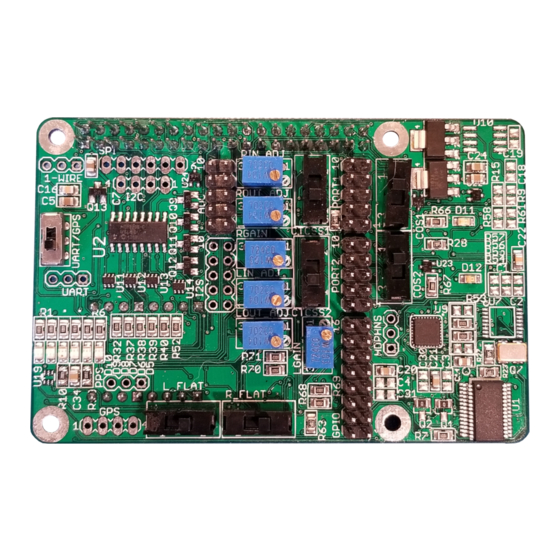
I2C Expansion Header SPI Expansion Header I2S Expansion Header PORT 2 1-Wire Header UART Header (shared with GPS) PORT 1 Stacking PI Stacking Header Header WWW.ICS-CTRL.COM USER MANUAL FOR HARDWARE REV 3.11 07-APR-2018 PAGE 3... -
Page 4: Independent Repeater Channels
(for active high rigs, not installed by default, contact us if you need this functionality) 3.1.1 REPEATER CHANNEL 1 Input AUDIO Adjust Output AUDIO Adjust FLAT AUDIO SELECT Output Amplifier Gain CTCSS HI <-> LOW PORT 1 PIN 1 LOW <-> HI Interface WWW.ICS-CTRL.COM USER MANUAL FOR HARDWARE REV 3.11 07-APR-2018 PAGE 4... -
Page 5: Repeater Channel 2
The input audio should be approximately <TBD> volts peak to peak as measured at Q1/Q2 (Bottom left corner near mounting hole) as applicable for the channel being measure. WWW.ICS-CTRL.COM USER MANUAL FOR HARDWARE REV 3.11 07-APR-2018... -
Page 6: Flat Audio Select
This switch is used to select the active on state for the COS signal from the receiver radio. Typically this will be active low, but some radios output an active high signal. This input can be used for 3-18Vdc signal levels. WWW.ICS-CTRL.COM USER MANUAL FOR HARDWARE REV 3.11 07-APR-2018... -
Page 7: Port Connector & Pin 1
Digikey, or a similar variant. STANDARD IDC RIBBON CABLE CONNECTORS WILL NOT FIT. Pin 1 is located in the bottom left corner as shown above in section 3.1. When using ICS-CTRL provided DB9 connectors, will correspond with the brown wire. -
Page 8: Analog To Digital Converter
2 header. For custom cables we suggest using connector block 952-2037-ND from Digikey, or a similar variant. STANDARD IDC RIBBON CABLE CONNECTORS WILL NOT FIT. WWW.ICS-CTRL.COM USER MANUAL FOR HARDWARE REV 3.11 07-APR-2018 PAGE 8... -
Page 9: Gps Option
Note: Use of this chipset requires a user developed Device Tree Overlay to prevent interference with the PTT and existing GPIO expander functionality. The provided overlays only support the chipset already on-board, which is part of the repeater board’s core functionality. WWW.ICS-CTRL.COM USER MANUAL FOR HARDWARE REV 3.11 07-APR-2018... -
Page 10: Spi Expansion
A 3 pin header has been included to allow for specialized 1-wire devices to be used. This is provided for user design and devices on this port are not supported by ICS-CTRL. This port connects directly to the processor and misconnected devices may cause damage to the system. -
Page 11: Uart Header
It is critical to remember that the signals on this connecter are 3.3V logic, and 5V logic levels can damage your devices. WWW.ICS-CTRL.COM USER MANUAL FOR HARDWARE REV 3.11 07-APR-2018... -
Page 12: Getting Started With Svxlink
Sample configurations will be provided on our Yahoo group and our website as we get them created. If you have a specific hardware need, please make the request to the Yahoo Group for ICS-Controllers or for SVXlink support, at the SVXlink support page respectively. Both pages have a good support community and we monitor the ICS-Controllers group actively. -
Page 13: Schematic
SCHEMATICS EMBEDDED PDF, open for high resolution copy WWW.ICS-CTRL.COM USER MANUAL FOR HARDWARE REV 3.11 07-APR-2018 PAGE 13... - Page 14 The pull up resistors for the COS (R10 and R19) and CTCSS (R12 and R17) inputs are incorrect value at 1.0 kohm. These resistors need to be replaced with 2.2 kohm (0805 size) to achieve proper operation when using active high. Board Top Side Board Bottom Side WWW.ICS-CTRL.COM USER MANUAL FOR HARDWARE REV 3.11 07-APR-2018...
Need help?
Do you have a question about the PI-REPEATER-2X and is the answer not in the manual?
Questions and answers