Table of Contents
Advertisement
Quick Links
Advertisement
Table of Contents

Related Manuals for Temspec VER1800


Summary of Contents for Temspec VER1800
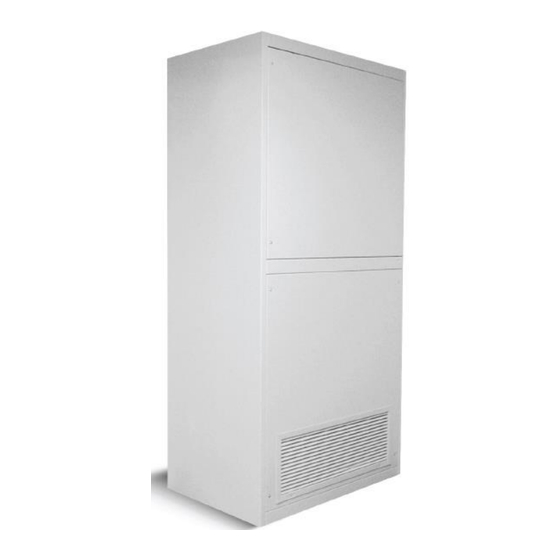
- Page 1 Operation & Maintenance Manual VER Vertical Unit Ventilator with Integral Energy Recovery IMPORTANT: Read and save this manual for future reference. This manual is to be left with the equipment owner Form SC-OM-MANUAL ©2011 Temspec Incorporated...
-
Page 2: Table Of Contents
Table of Contents INTRODUCTION About the VER ........................2 Nomenclature for VER ....................... 2 TYPICAL UNIT LAYOUT Model VER 1800 (ducted) ....................3 OPERATION Sequence of Operation ..................... 4 Hot Water Circuit ........................ 5 Refrigeration Circuit......................6 Electrical Circuit ......................... 7 Dampers .......................... -
Page 3: Introduction
INTRODUCTION ABOUT THE ENERGY RECOVERY UNIT VENTILATOR The Temspec integrated energy recovery unit ventilator was designed as a means for providing energy efficient heating, cooling and ventilation to the classroom. Our goal is to help create an enhanced learning environment by focusing on the following points when designing our equipment: •... -
Page 4: Typical Unit Layout
TYPICAL LAYOUT Models VER 1800 – HW / DX Split (ducted configuration) SA = Supply Air VA = Ventilation Air ECA = Economizer Air RA = Return Air EA = Exhaust Air ITEM NO. DESCRIPTION ITEM NO. DESCRIPTION ITEM NO. DESCRIPTION Evaporator Coil ERV Exhaust Filter... -
Page 5: Operation
OPERATION Typical Modes of Operation The following is a control strategy table for a VER 1800 with integral ERW, powered exhaust and W7212 Honeywell Economizer Module. The UV has one stage of DX cooling and modulating hydronic heat. NOTE: The Economizer, based on an increased requirement for cooling can modulate the Outdoor Damper in full-open position. -
Page 6: Hot Water Circuit
Hot Water Circuit The following is a typical hot water piping schematic for the VER 1800. Please refer to the shop drawings for a more specific layout. Hot Water with 2-Way Control Valve ITEM NO. DESCRIPTION ITEM NO. DESCRIPTION Hot Water Coil Valve, 2-Way, Modulating Manual Air Vent Actuator - Modulating... -
Page 7: Refrigeration Circuit
DX Refrigeration Circuit The following is a typical DX Split piping schematic. Please refer to the shop drawings for a more specific layout. ITEM NO. QTY DESCRIPTION Coil – DX – R410A Valve – Access – With Core – 600psi Controller –... -
Page 8: Electrical Circuit
Electrical Circuit The electrical circuit in the VER 1800 is dependent on the controller and sequence that is being utilized. The unit can be supplied with a 115V, 208V, 277V or 460V power supply. The unit is equipped with an unfused service disconnect. A copy of the electrical schematic can be found folded in a pouch inside of unit ventilator located on the electrical enclosure or supply air fan housing. -
Page 9: Maintenance
MAINTENANCE Servicing the Unit Maintenance to the unit is accomplished by removing the front access panels. Typically, the panels are secured by heavy duty Phillips (star or cross shape) head screws. When removing the access panel, loosen but do not remove the screws. Carefully store the panel in a place where it will not get damaged. -
Page 10: Changing The Filters
The outdoor and indoor conditions of your area will determine the frequency of filter changes. Temspec recommends that the filters be changed every 3 months as a rule-of- thumb. Note that dirty filters adversely affect the overall performance of the unit. -
Page 11: Cleaning The Evaporator Coil
CAUTION: Disconnect power before servicing the unit. Temspec recommends that the ERV desiccant wheel be cleaned with a vacuum periodically and that the use of a cleanser is only required when the necessary. When cleaning the wheel with a vacuum take care not to damage the wheel’s polymer material. -
Page 12: Troubleshooting
TROUBLESHOOTING Basic Trouble Shooting Guidelines Problem Action Required ● Supply fan not running ● Verify that the disconnect is in the “on” position ● Verify that door micro-switch “kill switch” is completely depressed and operating correctly ● Verify that thermostat / controller is not in unoccupied mode (night set-back) ●... -
Page 13: Replacement Parts
REPLACEMENT PARTS Limited Warranty TEMSPEC INCORPORATED warrants the equipment from factory defects in material or workmanship for a period of one year. For this warranty to be valid, the unit(s) must be installed and maintained in accordance with the manufacturer’s printed instructions.
Need help?
Do you have a question about the VER1800 and is the answer not in the manual?
Questions and answers