
Related Manuals for Temspec VUD Series


Summary of Contents for Temspec VUD Series
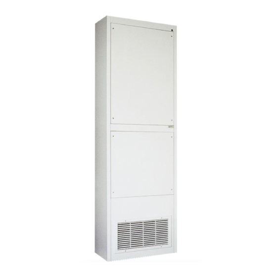
- Page 1 Operation & Maintenance Manual VUD, VUF, VDF & HCD Series Unit Ventilator IMPORTANT: Read and save this manual for future reference. This manual is to be left with the equipment owner © 2006 TEMSPEC INCORPORATED...
-
Page 2: Table Of Contents
Table of Contents INTRODUCTION ….……………………………………………………………………2 About the Unit Ventilator ………….……………………2 Nomenclature for non-compressorized Unit Ventilators TYPICAL UNIT LAYOUT ……………………………………………………….………………………3 Model VUD 1200 ……………………………………………………….………………………4 Model VUD 1600 ……………………………………….………………………………………5 Model VUD 2000 ……………………………………………………….………………………6 Model VUF 1200 ……………………………………………………….………………………7 Model VUF 1500 ……………………………………………………….………………………8 Model VDF 1200 ……………………………………………………….………………………9 Model HCD 1200 ……………………………………………………….………………………10... -
Page 3: Introduction
INTRODUCTION ABOUT THE UNIT VENTILATOR The Temspec unit ventilator is designed as means for providing heating, cooling and ventilation to the classroom. Our goal is to help create an enhanced learning environment by focusing on the following points when designing our equipment: •... -
Page 4: Typical Unit Layout
TYPICAL LAYOUT Model VUD 1200 (Upflow, Ducted Configuration) S.A. S.A. Duct By Others 93" O.A. O.A. R.A. R.A. 21.5" 21.5" 28" SIDE SECTION SIDE SECTION FRONT ELEVATION (Split System DX) (Hot Water / Chilled Water) S.A. Supply Air R.A. Return Air O.A. -
Page 5: Model Vud 1600
TYPICAL LAYOUT Model VUD 1600 (Upflow, Ducted Configuration) S.A. S.A. Duct By Others 93" O.A. O.A. R.A. R.A. 23" 23" 33" SIDE SECTION SIDE SECTION FRONT ELEVATION (Split System DX) (Hot Water / Chilled Water) S.A. Supply Air R.A. Return Air O.A. -
Page 6: Model Vud 2000
TYPICAL LAYOUT Model VUD 2000 (Upflow, Ducted Configuration) S.A. S.A. Duct By Others 93" O.A. R.A. O.A. R.A. 23" 23" 44" SIDE SECTION SIDE SECTION FRONT ELEVATION (Split System DX) (Hot Water / Chilled Water) S.A. Supply Air R.A. Return Air O.A. -
Page 7: Model Vuf 1200
TYPICAL LAYOUT Model VUF 1200 (Upflow, Freeblow Configuration) S.A. S.A. S.A. S.A. 93" O.A. O.A. R.A. R.A. 21.5" 21.5" 28" SIDE SECTION SIDE SECTION FRONT ELEVATION (Split System DX) (Hot Water / Chilled Water) S.A. Supply Air R.A. Return Air O.A. -
Page 8: Model Vuf 1500
TYPICAL LAYOUT Model VUF 1500 (Upflow, Freeblow Configuration) S.A. S.A. S.A. S.A. 93" R.A. O.A. O.A. R.A. 23" 23" 44" SIDE SECTION SIDE SECTION FRONT ELEVATION (Split System DX) (Hot Water / Chilled Water) S.A. Supply Air R.A. Return Air O.A. -
Page 9: Model Vdf 1200
TYPICAL LAYOUT Model VDF 1200 (Downflow Configuration) R.A. R.A. O.A. O.A. 93" S.A. S.A. 21.5" 21.5" 28" SIDE SECTION SIDE SECTION FRONT ELEVATION (Split System DX) (Hot Water / Chilled Water) S.A. Supply Air R.A. Return Air O.A. Outdoor Air 8. -
Page 10: Model Hcd 1200
TYPICAL LAYOUT Model HCD 1200 (Horizontal Configuration) 93" Duct By Duct By Others Others O.A. S.A. 21.5" R.A. Suspension SIDE SECTION Rods By Optional Others O.A. intake location 10" x 12" O.A. Supply Air O.A. Duct By Opening Others R.A. R.A. -
Page 11: Model Hcd 1600
TYPICAL LAYOUT Model HCD 1600 (Horizontal Configuration) 93" Duct By Duct By Others Others O.A. S.A. 23" R.A. SIDE SECTION Suspension Optional Rods By O.A. intake Others location 12" x 10" O.A. O.A. Supply Air Duct By Opening Others R.A. S.A. -
Page 12: Operation
OPERATION Typical Modes of Operation The following are typical modes of operation for a classroom unit ventilator. Please refer to the manual provided by the control’s contractor for a more specific controls sequence. 1. Unoccupied Condition During the “unoccupied heat” mode (night set-back) space temperature is maintained by a signal from the thermostat/controller to either the modulating control valve, modulating face and bypass damper actuator or electric coil triac. -
Page 13: Hot Water Circuit
Hot Water Circuit The following are typical hot water piping schematics for a unit ventilator. Please refer to the unit ventilator “shop drawings” for a more specific layout. Hot Water / Chilled Water with 2-way Control 2-way Control Valve Balancing Valve Manual Air Vent Isolation Valve Return... -
Page 14: Refrigeration Circuit
Refrigeration Circuit The following is a typical split system refrigeration circuit. Anti-Ice Control Distributor Metering Device MIXED EVAPORATOR COIL TEMSPEC UNIT VENTILATOR REMOTE CONDENSING UNIT Sight Glass, Moisture Indicator High Limit Cut-Out Pressure Test Port Low Limit Cut-Out OUTDOOR Compressor... -
Page 15: Electrical Circuit
Electrical Circuit The electrical circuit in the unit ventilator is highly dependent on the controller and sequence that is being utilized. The unit can be supplied with a 115V, 208V, 277V or 460V power. Each unit comes standard with an unfused disconnect. A copy of the electrical schematic can be found folded in a pouch inside of the unit ventilator. -
Page 16: Maintenance
MAINTENANCE Servicing the Unit Access to the components is gained by removing the front access panels. Typically, the panels are fastened by heavy duty Phillips head screws. When removing the access panel (vertical style units), loosen but do not remove the screws. Carefully store the panel in a place where it will not get damaged. -
Page 17: Changing The Filters
Changing the Filters The outdoor and indoor conditions will determine the frequency of filter changes. Temspec recommends that the filters be changed every 3 months as a rule-of-thumb. Note that dirty filters will affect the overall performance of the unit. -
Page 18: Troubleshooting
The Refrigerant type and the amount is posted on the metallized CSA label located on the fan housing. : Temspec does not recommend the use of a Unit Ventilator during NOTE construction/drywall installation as a space heater or air conditioner. -
Page 19: Replacement Parts
REPLACEMENT PARTS Limited Warranty TEMSPEC INCORPORATED warrants the equipment from factory defects in material or workmanship for a period of one year. For this warranty to be valid, the unit(s) must be installed and maintained in accordance with the manufacturer’s printed instructions.
Need help?
Do you have a question about the VUD Series and is the answer not in the manual?
Questions and answers