Table of Contents
Advertisement
Quick Links
7400
GPLIMT/GPLIM User Manual
Every effort has been made to eliminate errors and ambiguities in the information contained in this guide.
Any
questions
concerning
information
presented
here
should
be
directed
to
SAMSUNG
TELECOMMUNICATIONS AMERICA, 1301 E. Lookout Dr. Richardson, TX. 75082 telephone (972) 761-
7300. SAMSUNG TELECOMMUNICATIONS AMERICA disclaims all liabilities for damages arising from
the erroneous interpretation or use of information presented in this guide.
Advertisement
Table of Contents

Related Manuals for Samsung OfficeServ 7400 GPLIMT


Summary of Contents for Samsung OfficeServ 7400 GPLIMT
- Page 1 SAMSUNG TELECOMMUNICATIONS AMERICA, 1301 E. Lookout Dr. Richardson, TX. 75082 telephone (972) 761- 7300. SAMSUNG TELECOMMUNICATIONS AMERICA disclaims all liabilities for damages arising from the erroneous interpretation or use of information presented in this guide.
- Page 2 Samsung Telecommunications Publication Information SAMSUNG TELECOMMUNICATIONS AMERICA reserves the right without prior notice to revise information in this publication for any reason. SAMSUNG TELECOMMUNICATIONS AMERICA also reserves the right without prior notice to make changes in design or components of equipment as engineering and manufacturing may warrant.
-
Page 3: Introduction
CHAPTER 2. Installing OfficeServ 7400 GPLIMT/GPLIM This chapter describes the installation procedure and login procedure. CHAPTER 3. Using OfficeServ 7400 GPLIMT/GPLIM This chapter describes how to use the menus of the OfficeServ 7400 GPLIMT/GPLIM. ABBREVIATIONS Abbreviations frequently used in this document are described. -
Page 4: Conventions
Conventions The following types of paragraphs contain special information that must be carefully read and thoroughly understood. Such information may or may not be enclosed in a rectangular box, separating it from the main text, but is always preceded by an icon and/or a bold title. WARNING Provides information or instructions that the reader should follow in order to avoid personal injury or fatality. -
Page 5: References
References OfficeServ 7400 General Description The OfficeServ 7400 General Description introduces the OfficeServ 7400 platform and presents the system information necessary to understand the hardware configuration, specification, and system functionality. OfficeServ 7400 Installation Manual The OfficeServ 7400 Installation Manual describes the conditions necessary for the installation of the system and how to inspect and operate the system. -
Page 6: Safety Concerns
SAFETY CONCERNS For product safety and correct operation, the following information must be given to the operator/user and shall be read before the installation and operation. Symbols Caution Indication of a general caution. Restriction Indication for prohibiting an action for a product. Instruction Indication for commanding a specifically required action. -
Page 7: Caution
If not, set to Disable. When Changing DB If DB is changed in OfficeServ 7400 GPLIMT/GPLIM, the system restarts. When Activating Server Authentication Login Policy should be applied first to activate the server authentication to the system. If... -
Page 8: Table Of Contents
Symbols ........................VI Caution ........................VII CHAPTER 1. Overview of OfficeServ 7400 GPLIMT/GPLIM Introduction to OfficeServ 7400 ..................10 Introduction to OfficeServ 7400 GPLIMT/GPLIM Data Switch ........11 CHAPTER 2. Installation of OfficeServ 7400 GPLIMT/GPLIM Installing..........................13 Getting Started........................15 Port ............................ 17 Port ............................ - Page 9 System..........................56 Network ........................57 DB Config ........................58 Admin Config ....................... 59 Log..........................60 Time Configuration....................... 62 Upgrade ........................64 Appl Server ........................64 Reboot ......................... 65 Utility..........................65 Management Menu ......................67 SNMP .......................... 68 RMON.......................... 71 My Info Menu........................74 ABBREVIATION A~L ..........................
-
Page 10: Chapter 1. Overview Of Officeserv 7400 Gplimt/Gplim
CHAPTER 1. Overview of OfficeServ 7400 GPLIMT/GPLIM This chapter introduces the OfficeServ 7400 system and OfficeServ 7400 GPLIMT/GPLIM Data Switch. Introduction to OfficeServ 7400 The OfficeServ 7400 platform delivers the convergence of voice, data, wired and wireless communications for small and medium sized businesses. This ‘office in a box’ solution offers... -
Page 11: Introduction To Officeserv 7400 Gplimt/Gplim Data Switch
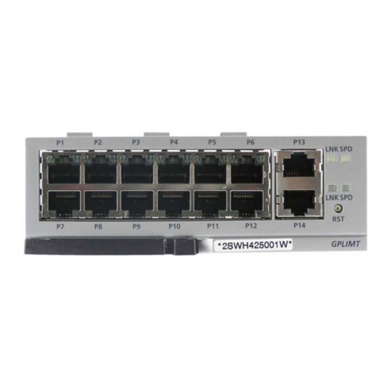
Introduction to OfficeServ 7400 GPLIMT/GPLIM Data Switch GPLIM Module GPLIMT Module OfficeServ 7400 provides the following functions: Ethernet Switch Function Fast Ethernet L2 switch module(compatible with IEEE 802.3) Managed switch function by using an access interface for LAN Twelve 10/100-BASE-TX Fast Ethernet ports: LAN interface between terminal devices... - Page 12 Management Function Configuration and verification functions for the operations of GPLIMT/GPLIM functional block via a browser Configuration and verification functions for the operations of GPLIMT/GPLIM functional block via the Simple Network Management Protocol(SNMP) 4-Real-time Monitoring(4RMON) function Program upgrade − Program upgrade via TFTP −...
-
Page 13: Chapter 2. Installation Of Officeserv 7400 Gplimt/Gplim
CHAPTER 2. Installation of OfficeServ 7400 GPLIMT/GPLIM This chapter describes the installation and the login procedure for OfficeServ 7400 GPLIMT/GPLIM. Installing OfficeServ 7400 GPLIMT/GPLIM software is pre-installed. The software package is composed of the following items described below: Package File... - Page 14 GPLIMT/GPLIM Installation Insert the GPLIMT/GPLIM into an open slot in the OfficeServ 7400 cabinet (excluding slots 0 or 3 which are reserved for the MP40 and LP40 cards). Connect a PC to any port (P1 –P12) of the GPLIMT/GPLIM module with either a straight or cross over cable..
-
Page 15: Getting Started
Getting Started Start Internet Explorer and enter the IP address of the GPLIMT/GPLIM management IP Address into the address bar. The Security Alert window shown below will appear. Click on the Yes button to proceed: A Security Information window will now open. Click on the Yes button to proceed. The Administrator will now be prompted for a Login ID and Password. - Page 16 Log into the GPLIMT/GPLIM using the administrator ID and password and then click on the OK button. The following Security Information window will appear again. Click on the Yes button to proceed. The GPLIMT/GPLIM menus are displayed in the upper part of the screens. Select each menu to display its submenus on the left section of the screen.
- Page 17 CHAPTER 3. Use of OfficeServ 7400 GPLIMT/GPLIM This chapter describes the menus of the OfficeServ 7400 GPLIMT/GPLIM. The OfficeServ 7400 GPLIMT/GPLIM Data Switch menus are arranged as shown below:...
-
Page 18: Port
Port The [Port] menu is used by the administrator to configure the individual switch port settings such as speed, duplex, and flow control, to configure VLANs, to statically assign MAC Addresses to switch ports, and to assign MAC Address filtering. Select the [Port] menu and the submenus will be displayed in the upper left side of the window as follows: Port Menu Description Menu... -
Page 19: Port
Menu Submenu Description Static Address Used to store a MAC address to the static address table. Dynamic Used to retrieve a floating address table or to Address delete a MAC address. Filter Address Used to enter a MAC address and sets to filter the frame data that has the same MAC address information with the entered value in the switch. - Page 20 Port Configuration Parameter Description Parameter Description Port Used to display the port number Active Used to set whether to use a port or not. Negotiation - Auto: Adjusts the speed through a negotiation with the counterpart. - Force: Sets the speed without a negotiation with the counterpart. Set the negotiation item as ‘Force’...
- Page 21 Statistics The administrator can retrieve the link status and statistics for each port on the GPLIMT/GPLIM switch using the [Port] [Port] [Statistics] submenu. In order to reset the statistics click the Reset button. Port Statistics Field Description Field Description Input Used to display the number of packets received Packets Input...
- Page 22 MISC The administrator can set up the port mirroring feature and adjust the MAC Age-out Timer, the Broadcast Storm Filter, and the Auto MDI/MDIX parameters using the [Port] [Port] [MISC] submenu. MISC Parameter Description Parameter Description Mode Used to set up the mirroring function. - Off: Mirroring function not used - Receive: Mirroring for incoming packets - Transmit: Mirroring for outgoing packets...
- Page 23 The GPLIMT/GPLIM Layer 2 QoS configuration is performed using the [Port] [Port] [QoS] submenu. QoS Parameter Description Parameter Description QoS Mode Used to select the QoS mode. - First Come First Service: Packets are transmitted according to there incoming order.(QoS function not used) - All High before Low: When a packet has a higher priority it is transmitted prior to a packet with a lower priority.
-
Page 24: Vlan
VLAN VLANs are used to divide a network into smaller networks to reduce the traffic and for security purposes. The [Port] [VLAN] submenu is used to configure VLANS, Port VIDs, and VLAN Classifications. Configuration Using the [Port] [VLAN] [Configuration] submenu the administrator can configure the VLAN features. - Page 25 contain port information, the port serves as a VLAN member by receiving packets. Thus, the ARP packet must be transmitted to the switch to enable members of a VLAN to exchange packets. Port Based VLAN The Port based VLAN is configured with an access list specifying membership in a set of VLANs..
- Page 26 802.1Q IVL and SVL based VLAN The 802.1q IVL and SVL based VLANs have two groups of boxes. The top grouping (in black) is used to assign untagged ports, and the bottom grouping (in blue) is used to assign tagged ports. VLAN Untagged Members: Select the port/s that will send the Ethernet frame that deletes the TCI (Tag Control Information).
- Page 27 Port VID For an ethernet packet to have a VLAN ID the tag must be written by an Ethenet adapter or Switch. Using the [Port] [VLAN] [Port VID] submenu the administrator will assign the VLAN IDs to specific ports. Port VID Parameter Description Parameter Description Port VID...
- Page 28 Classification Using the [Port] [VLAN] [Classification] submenu the administrator can define the VLAN Classification Rules. 802.1Q (IVL and SVL) If an untagged frame is received it can be classified according to protocol. The rule values are set to decide which VLAN ID is attached to a frame. VLAN Configuration Field/Parameter Description Field/Parameter Description...
- Page 29 MAC Based VLAN Frames coming into a switch can be marked for a particular VLAN based on the source MAC Address VLAN Classification Parameter Description Field/Parameter Description Classification Mode This field is defined automatically according to the VLAN mode. When the mode is MAC ‘mac’ is selected Classification Rule According to the received packet via a defined MAC address the VLAN can be set.
-
Page 30: Mac
The [Port] [MAC] submenu is used to assign MAC addresses to ports, to view dynamic MAC address tables, and to assign MAC address filtering. Static Address The [Port] [MAC] [Static Address] submenu is used to enter a specific MAC address in the MAC address table. - Page 31 Dynamic Address In order to view the dynamically learned MAC addresses use the [Port] [MAC] [Dynamic Address] submenu. Filter Address By using the Mac filtering feature on the GPLIMT/GPLIM it is possible to block unwanted traffic on the network. The [Port] [MAC] [Filter Address] submenu is used to enter MAC addresses that are to be filtered.
-
Page 32: Layer2
Layer2 The Layer 2 Menu is used to configure the Spanning Tree Protocol, GVRP, IGMP, and port based authentication. Once the [Layer2] menu is selected the submenus will be displayed in the upper left side of the window as follows: Layer 2 Menu Description Menu Submenu... -
Page 33: Rstp
RSTP Configuration The Spanning Tree Protocol (STP) and Rapid Spanning Tree Protocols (RSTP) provide a loop free topology for any bridged LAN. Use the [Layer2] [RSTP] [Configuration] submenu to begin configuring the RSTP and STP settings. - Page 34 RSTP Protocol Status/Bridge/Port Parameter Description Parameter Description Protocol Status Used to display the current status of the RSTP protocol. Bridge Used to configure the Bridge parameters of the switch that Parameter RSTP uses. - Bridge Priority: Used to set the priority of Bridges. - Hello Time: Used to set the transmission cycle of BPDU.
- Page 35 Status The [Layer2] [RSTP] [Status] submenu is used to display the status of the switch RSTP operation. RSTP Bridge Status Field Description Field Description Protocol Status Used to show the RSTP status Designated Used to display the GPLIMT/GPLIM’s bridge information in Bridge Identifier hexadecimal numbers.
- Page 36 Field Description Last Topology Used to display the most recent time that the RSTP network Changed was reconfigured due to a change in the network configuration. RSTP Port Status Field Description Field Description Port Name Used to display the port number Port ID The value is combined with the value of the port priority and the ID value of the port specified in the system.
-
Page 37: Port Aggregation
Port Aggregation In order to use multiple transmission paths between network devices so there can be an increase in transmission speeds then the Port Aggregation feature can be used. Select the [Layer2] [Port Aggregation [Configuration] submenu to begin configuring Port Aggregation. - Page 38 Member Configuration Parameter Description Parameter Description Group ‘S’ represents a static trunk, and ‘L’ represents a LACP (Link Aggregation Control Protocol) trunk. Up to eight groups can be used and up to four ports can be included in one group as members.
-
Page 39: Gvrp
GVRP GVRP (GARP VLAN Registration Protocol) is a protocol that facilitates control of virtual local area networks (VLANs) within a network. It defines a method of tagging frames with VLAN configuration data. This allows network devices to dynamically exchange VLAN configuration information with other devices. - Page 40 GVRP Configuration Field/Parameter Description Field/Parameter Description Port Used to display the port Number Status Used to enable or disable GVRP per port Used to display the Registration mode as Normal, Forbidden or Registration Fixed Used to display the Applicant mode as Normal or Active Applicant conditions Join...
- Page 41 GVRP Statistics Field Description Field Description Port Used to display the Port Number Join Empty Used to display the number of Join Empty packets Join In Used to display the number of Join In packets Leave Empty Used to display the number of Leave Empty packets Leave In Used to display the number of Leave In packets Empty...
-
Page 42: Igmp Snooping
IGMP Snooping The purpose of Internet Group Management Protocol (IGMP) snooping is to restrain multicast traffic in a switched network. The [Layer2] [IGMP Snooping] menu is used for the configuration of IGMP Snooping. Time Interval Use the [Layer2] [IGMP Snooping] [Time Interval] submenu to configure the time related parameters of IGMP Snooping. - Page 43 Function Use the [Layer2] [IGMP Snooping] [Function] submenu to specify the functions related to IGMP Snooping. IGMP Snooping Function Category Description Categories Description VLAN Pull down menu used to select the VLAN to be configured. Querier Used to specify the operation as IGMP querier when the multicast router does not exist.
- Page 44 Forwarding Table Use the [Layer2] [IGMP Snooping] [Forwarding Table] submenu to display the information on the members registered in IGMP Group. Click the Refresh button to update the information displayed on the web screen. Management Use the [Layer2] [IGMP Snooping] [Management] to specify the operation of IGMP Snooping.
-
Page 45: Authentication
Authentication The [Authentication] submenu is used to enable or disable remote authentication, to review existing authentication information, and to configure individual ports and their authentication methods. Management Use the [Layer2] [Authentication] [Management] submenu to turn authentication on or off and to define the Radius server management items. Click the Run button to start the service and click the Stop button to cease the authentication service. - Page 46 Configuration Use the [Layer2] [Authentication] [Configuration] submenu to configure the authentication method on a per port basis. If the authentication service has not been started the following window will appear: Once the service is started using the [Layer2] [Authentication] [Management] submenu the following window will appear when using the [Layer2] [Authentication] [Configuration] submenu...
- Page 47 Parameter Description Tx-Period Used to set the cycle that sends Request regularly to supplicant. (1-65535sec) default: 30 sec Supp-Timeout Used to set the time before re-sending to the user when EAP is requested.(1-65535sec) default: 30 sec Sever-Timeout Used to set the time before re-sending to the device when server authentication of a server is requested.(1-65535sec) default: 30 sec The Re-authentication settings and cycle settings are applied only when the setting is changed...
-
Page 48: Application
Application The [Application] menu is used to view the status of VoIP Service and to start or stop the VoIP service. The submenus will be displayed in the upper left side of the window as follows: VoIP Service This [Application] [VoIP Service] submenu is used to start or stop the VoIP Service. -
Page 49: Poe
The [PoE] menu is used to configure, edit, and view the GPLIMT/GPLIM PoE settings. The submenus will be displayed in the upper left side of the window as follows: PoE Menu Description Menu Submenu Description Global Used to set or retrieve the PoE version information and power supply information. - Page 50 Global Select the [PoE] [Global] submenu to check the PoE version information and power supply information. In addition this menu is used to set the Power Management Mode. PoE Global Field Description Field Description PoE Software Version Used to display the PoE Software version. PoE DEV.Version(0, 1, 2) Used to display the number of ports of each PoE chip and the hardware version.
- Page 51 When the administrator sets the Power Management Mode the power supply type is selected depending on the Power Device (PD) terminal power. Use the ‘Dynamic’ setting to make the maximum power of 18.9 W available for each port. Use the ‘Static’ setting to make the restriction of power definable. Use the ‘Class’ setting to decide upon the restriction of the PoE power depending on the PD terminal PD Classes which are are described as follows: PoE Power Management Class Power Description...
- Page 52 Configuration Select the [PoE] [Configuration] submenu to retrieve and set the power information for each port. PoE Configuration Parameter Description Parameter Description Port Used to indicate the Ethernet port 1~12 being configured. Enable Used to sets or release the PoE power supply of the target port.
- Page 53 Power Status Select the [PoE] [Power Status] submenu to display the PoE power supply status of all ports in real time. PoE Power Status Field Description Field Description Port Used to display the Ethernet port 1~12. Enable Used to display the status of Power management for each port.
- Page 54 Port Status Select the [PoE] [Port Status] submenu to display the current status of all ports in real time. PoE Port Status Field Description Field Description Port Used to display the Ethernet port 1~12. Status Used to display the current PoE information for each port. Management Select the [PoE] [Management] submenu to start or stop the PoE Manager.
- Page 55 Select the [PoE] [Log] submenu to set the PoE log report attributes. PoE Log Parameter Description Parameter Description PoE Log - Enable: Enables PoE Log Manager. - Disable: Disables PoE Log Manager. Version Used to set the Version information to On in the PoE Global menu.
-
Page 56: System
System The System Menu is used to import or export the GPLIMT/GPLIM database, to view system logs, to set time attributes, to upgrade the software, and to reboot the system. Select the [System] menu and the submenus will be displayed in the upper left side of the window as follows: System Menu Description Menu... -
Page 57: Network
Menu Submenu Description Appl Server Used to allow remote access to the GPLIMT/GPLIM via SSH, FTP, and Telnet. Reboot Used to reboot the system. Utility Ping Used to execute a Ping test Network The [System] [Network] submenu is used to set the Management IP address and DNS information for the GPLIMT/GPLIM. -
Page 58: Db Config
DB Config Use the [System] [DB Config] submenu to export the GPLIMT/GPLIM database, to import the GPLIMT/GPLIM database, or to default the GPLIMT/GPLIM to the factory defaults. DB Config Parameter Description Parameter Description Import Used to restore a previously saved database Export Used to save the existing DB Default... -
Page 59: Admin Config
Admin Config The [System] [Admin Config] submenu is used to set up the authentication server for logging into the GPLIMT/GPLIM and for changing the Web Time-out configuration. The choices for authentication server are Local, Radius or Taccas+ . Check the box of the authentication method desired and then click the OK button to save the change. -
Page 60: Log
Taccas+ If Taccas+ will be used then select the Taccas+ box. Enter the information for the Taccas+ authentication method. Up to 5 lists can be entered. When deleting the list of all the server IPs, the corresponding secret key values are also deleted. The [System] [Log] submenu is used to allow the system log, to run system log reports, and to download a system log report to a file. - Page 61 Report Using the [System] [Log] [Report] submenu the administrator can retrieve the logs stored in the system according to attributes, date, and time. Click the radio button for the desired log type and then select the date and time. Then click the OK button to run the report.
-
Page 62: Time Configuration
Download Using the [System] [Log] [Download] submenu the administrator can download a log report to a PC. Simply press the Download button and the system log will be downloaded in the form of a compressed file. Time Configuration Using the [System] [Time Configuration] submenu the system administrator can either synchronize the date and time of the GPLIMT/GPLIM with a NTP server or manually set the date and time. - Page 63 Manual Config By using the [System] [Time Configuration] [Manual Config] submenu the administrator can manually set and modify the date and time of the GPLIMT/GPLIM. In the Date/Time Configuration window enter the desired date and time and then click the OK button to save the changes.
-
Page 64: Upgrade
[Appl Server] submenu the administrator can control remote access to the GPLIMT/GWPLIM using SSH, FTP and Telnet. In order to secure the system from hackers Samsung recommends that these are disabled and only turned on when the administrator needs to use them for debugging, and uploading or downloading files. -
Page 65: Reboot
Reboot Using the [System] [Reboot] submenu the administrator can reboot the GPLIMT/GPLIM. Simply click the OK button and all the services will be terminated and the system will reboot. The webscreen will return to the initial login window and the webscreen will not operate until the network and services are all up and running Utility The GPLIMT/GPLIM is able to do both basic ping and extended ping tests. - Page 66 Parameter Description Source Address Used to set the IP address of the interface for the Ping test Packet Size Used to set the packet size to be transmitted Retry Count Used to set the retry count. If it set to ‘0’, there is no retry.
-
Page 67: Management Menu
Management Menu The SNMP and RMON settings are configured and managed using the [Management] menu. The submenus will be displayed in the upper left side of the window as follows: Management Menu Description Menu Submenu Description SNMP Configuration Used to display the configuration items of SNMP. Status Used to display the SNMP configuration currently configured. -
Page 68: Snmp
SNMP Configuration SNMP is a set of protocols used for managing complex networks. The [SNMP] [Configuration] submenu is used by the administrator to enter SNMP System Options, SNMP Community information, SNMP v3 User information, and Trap Manager information. Once all the changes are entered then click the Save button at the bottom of the window. - Page 69 SNMPv3 Administrator Add The following window is used to enter the SNMPv3 Administrator v3 information. SNMP v3 Parameter Description Parameter Description Administrator Name Used to enter the new administrator’s name Administrator Used to enter the new administrator’s password (8 Password alphanumeric characters) Authentication Used to set up the authentication method.
- Page 70 Status The [Management] [SNMP] [Status] submenu is used to view the SNMP System Configuration information and to delete the SNMP Community, SNMPv3 User and SNMP Trap information. In order to delete the Community, User, and Trap settings select the box to the left of the item that needs to be deleted and then click the Delete button.
-
Page 71: Rmon
Management The [Management] [SNMP] [Management] submenu is used to start and stop the SNMP service. Click the Run button to start the SNMP service and click the Stop button to halt the SNMP service. SNMP Management SNMP Management Field Description Field Description Activity... - Page 72 RMON Configuration Parameter Description Parameter Description MAX History Buckets Used to set up the maximum history storage space. MIN History Interval Used to set up the minimum history sample collection cycle. Event Options The Event Options window is used to set up the RMON event options. RMON Event Options Parameter Description Parameter Description...
- Page 73 Field Description MIN History This field displays the minimum history sample collection Interval cycle. Max Event Logs This field displays the maximum number of logs that are set Saved Event Logs This field displays the number of logs that is currently stored.
-
Page 74: My Info Menu
My Info Menu Click the icon on the upper right hand side of the GWIMT/GWIM Web Page to open the My Info window. In this window administrators can enter a telephone number, an E- mail address, and desciption of the router . This window is also used to enter the admin password which is used when logging into the GWIMT/GWIM router. -
Page 75: Abbreviation
ABBREVIATION Address Resolution Protocol BPDU Bridge Protocol Data Unit Computer Telephony Integration Domain Name Server GPLIMT/GPLIM Gigabit PoE LAN Interface Module GVRP GARP VLAN Registration Protocol HTTP Hypertext Transfer Protocol IGMP Internet Group Management Protocol Local Area Network... -
Page 76: M~V
Media Access Control Network Address Translation Network Time Protocol Powered Device Power Of Etnernet Permanent Virtual Circuit PVID Port VLAN Identification Quality of Service RMON Realtime Monitoring RSTP Rapid Spanning Tree Protocol Spanning Tree Protocol SNMP Simple Network Management Protocol TFTP Trivial File Transfer Protocol VLAN...
Need help?
Do you have a question about the OfficeServ 7400 GPLIMT and is the answer not in the manual?
Questions and answers