Table of Contents
Advertisement
Quick Links
Advertisement
Table of Contents

Related Manuals for Rohde & Schwarz DDF205


Summary of Contents for Rohde & Schwarz DDF205
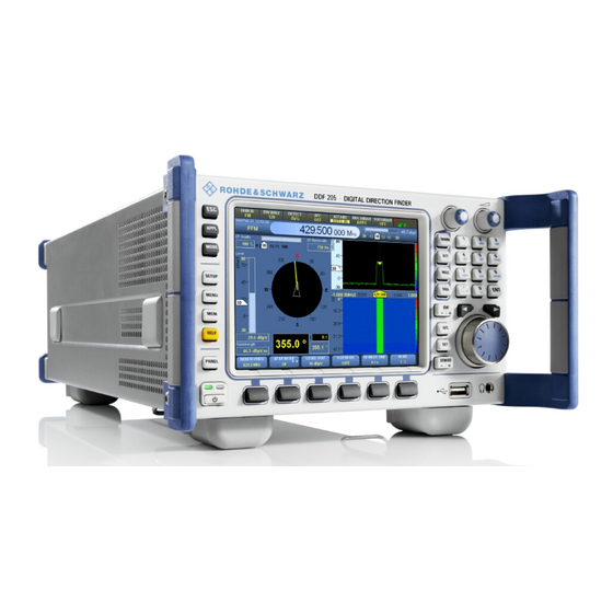
- Page 1 ® R&S DDF205 Digital Direction Finder Getting Started (X×1å2) 4073.0187.02 ─ 03...
- Page 2 DDF205 Digital Direction Finder 4073.0006.03 (with front control panel) The firmware of the R&S DDF205 makes use of several valuable open source software packages. Please refer to the "Open Source Acknowledgement" document (4072.8561.02) for a summary of the packages and the verbatim license texts.
-
Page 3: Table Of Contents
2.1.2 DDF205 without front control panel............15 2.2 Rear-Panel Tour..................17 2.3 Graphical User Interface (GUI)............19 2.3.1 GUI Layout....................19 2.3.2 Turning on the R&S DDF205 for the First Time........21 2.3.3 Online Help...................36 2.4 Options for the R&S DDF205.............40 2.4.1 Panorama Scan (R&S DDF205-PS).............40 2.4.2 ITU Measurement (R&S DDF205-IM)...........41... - Page 4 4.3.2 Firmware Update Using Update32 Tool..........60 4.4 GUI Installation for Remote Access..........64 4.4.1 Preparations..................64 4.4.2 Installation Procedure................65 4.5 Changing the IP Address..............69 4.5.1 Using Update32 Tool................69 4.5.2 Using GUI (DDF205 with front control panel or Remote Access GUI) ......................71 Getting Started 4073.0187.02 ─ 03...
-
Page 5: Preparation For Use
R&S DDF205 Specific Safety Instructions Preparation for Use This section describes the basic steps to be taken when setting up the R&S DDF205 for the first time. Specific Safety Instructions General safety instructions Please follow the basic safety instructions included in this documentation as well as the instructions for setup and connection to prevent personal injury or damage to the R&S DDF205. -
Page 6: Setup
Bench Operation Equipment cooling Do not expose the R&S DDF205 to humidity. Leave at least 50 mm of empty space along both side panels in order to ensure proper equipment cooling. There are no special requirements for desktop use. To facilitate access to the front panel elements, you should raise the front of the R&S DDF205 by folding out its... - Page 7 Setup Risk of injury The feet may fold in if they are not folded out completely or if the R&S DDF205 is shifted. The feet may break if they are overloaded. Fold the feet completely in or completely out to ensure stability of the R&S DDF205 and personal safety.
-
Page 8: Rack Mounting
1.2.5.1 Connecting to the Power Adapter The R&S DDF205 is connected to the AC supply 100 V to 240 V via an external AC/DC power adapter and to the socket X1 (10 VDC to 32 VDC) on the rear panel. - Page 9 Fig. 1-1: Speakon® NL4FX 1.2.5.2 Connecting to the DC Source The R&S DDF205 is connected to an external 10 VDC to 32 VDC source (e.g. battery) via connector X1 on the rear panel. Recommended connector: Neutrik® Speakon® NL4FX, see ...
-
Page 10: Power On And Off
DC power and disconnect the R&S DDF205 from the AC/DC power adapter. In READY state, the green LED on the left is on. The R&S DDF205 is ready for operation. All modules are being powered and the R&S DDF205 initiates its startup procedure. -
Page 11: Connecting External Accessories
Address", on page 69 for the steps needed to set the R&S DDF205’s IP address. 2. Connect a LAN cable to the LAN port. The R&S DDF205 has an internal switch which automatically detects the type of LAN cable connected so you can use any standard type of LAN cable to establish a network connection with the R&S DDF205 (dedicated or non-dedicated). - Page 12 ® Preparation for Use R&S DDF205 Setup Getting Started 4073.0187.02 ─ 03...
-
Page 13: Operation
Front-Panel Tour Operation Basic operation of the R&S DDF205 will be described in this chapter. An overview of the front panel, rear panel and graphical user interface (GUI) is explained below. This chapter contains most of the information required to access the various con- figuration options and settings necessary to get you started operating the R&S DDF205. - Page 14 3. Utility keys. ● ESC terminates an ongoing operation, e.g. by closing a dialog. ● APPL sets the R&S DDF205 to a particular application mode -- Receiver, Video, ITU (optional), Decode (optional). ● MODE changes the R&S DDF205 from a Fixed Frequency Mode (FFM) to one of the scanning modes.
-
Page 15: Ddf205 Without Front Control Panel
Allows stereo headphones with a 3.5 mm stereo plug to be connected. 2.1.2 DDF205 without front control panel An overview of the front-panel elements of the DDF205 without front control panel is given in the paragraph below. Getting Started 4073.0187.02 ─ 03... - Page 16 GUI for remote access A GUI for remote access is available for the Windows XP platform and is particularly useful for the DDF205 without front control panel because it gives functionality similar to the DDF205 with front control panel. Follow the instruc- tions in ...
-
Page 17: Rear-Panel Tour
Rear-Panel Tour Rear-Panel Tour The various inputs and outputs located on the rear panel of the R&S DDF205 are briefly explained in the paragraphs below. In the following overview, the index numbers refer to the labels in the figure above. - Page 18 ● Serial GPS devices according to the NMEA0183 standard. Either one of the X5 or X6 connectors can be used for an external GPS device, to determine the location and the exact time of the R&S DDF205. ● Serial compass devices according to the NMEA0183 standard. Use this con- nector for an external compass device to determine the direction of your vehicle.
-
Page 19: Graphical User Interface (Gui)
A CAT7 LAN cable must be used for this Gigabit capable interface. Graphical User Interface (GUI) This chapter provides a short description of the graphical user interface of the R&S DDF205. 2.3.1 GUI Layout Following is an overview of the layout and individual elements of the graphical user interface. - Page 20 Audio signal is available in stereo at current frequency. The R&S DDF205 is not locked. The R&S DDF205 is locked by another client. Access is not possible. The R&S DDF205 is locked. Only the current operator can make changes (exclusive write access).
-
Page 21: Turning On The R&S Ddf205 For The First Time
The squelch level is also shown by means of an indicating marker in the bar graph. Panel area The panel area is used for displaying the various panels of the R&S DDF205 (spectrum and waterfall are shown). ●... - Page 22 When a field is in edit mode (whether it is minutes, seconds, hours etc), it will not be updated. The R&S DDF205 time will be set to the new time once the field gets out of edit mode.
- Page 23 ® Operation R&S DDF205 Graphical User Interface (GUI) Softkey fadeout When the softkey options in the SETUP menu are not selected within 5 sec- onds, the menu will timeout and revert to the softkeys for the panel in focus. In this situation, the setup procedure should be repeated from the start.
- Page 24 Graphical User Interface (GUI) DF Antennas The R&S DDF205 can operate as a normal recever and use conventional antennas. However for the direction finder function to measure meaningful bearing data it is required to install a DF antenna, e.g. R&S ADD197, to the antenna port X13.
- Page 25 As stated before, the R&S DDF205 is able to operate as a normal receiver. Before proceeding with the DF functions, some fundamental receiver opera- tions will be explained first. Use the APPL key to switch the R&S DDF205 to receiver mode.
- Page 26 ® Operation R&S DDF205 Graphical User Interface (GUI) a) "MINIMUM": the minimum of the FFT trace over time is displayed. b) "MAXIMUM": the maximum of the FFT trace over time is displayed. c) "AVERAGE": the average of the FFT trace over time is displayed.
- Page 27 ® Operation R&S DDF205 Graphical User Interface (GUI) a) Select the "DEMOD FREQ" softkey to highlight it. b) With the softkey in (3a) highlighted, follow procedure (1) to change the demodulation frequency within the IF span. c) The Mid Frequency will not change.
- Page 28 ® Operation R&S DDF205 Graphical User Interface (GUI) a) The BW +/- key changes the demodulation bandwidth and the dark blue region displays the bandwidth in relation to the IF span. b) The AFC key toggles automatic frequency control. When a peak is within the demodulation bandwidth (3), AFC helps to track and keep the demodulation frequency tuned to the frequency of the peak.
- Page 29 ® Operation R&S DDF205 Graphical User Interface (GUI) c) Pressing the SELECT rollkey (5g) toggles the selected set of markers on and off. d) The ATT key selects the RF attenuation function. Pressing the SELECT roll- key (5g) toggles between automatic and manual attenuation. When in man- ual attenuation mode, turning the SELECT rollkey (5h) will allow the manual attenuation level to be set.
- Page 30 ® Operation R&S DDF205 Graphical User Interface (GUI) a) Select the "More 1 / 4", followed by "More 2 / 4" and "More 3 / 4" softkeys until page 4 / 4 of the menu. b) Select the "CONFIG IF PAN" softkey.
- Page 31 ® Operation R&S DDF205 Graphical User Interface (GUI) c) The IF Panorama dialog box will open. Change some of the settings and observe how the IF Panorama is displayed. - The first few fields allow to adjust the highest and lowest level to be dis- played in the IF panel.
- Page 32 ® Operation R&S DDF205 Graphical User Interface (GUI) DF Antenna and Compass Setup 1. Press the SETUP key. 2. Press "Peripherals" softkey to open the "Peripherals" selectors. 3. Open the Antenna Setup dialog. 4. The dialog shows the DF antenna ADD197. Check "Use Compass" and select the built-in compass GH150.
- Page 33 ® Operation R&S DDF205 Graphical User Interface (GUI) 5. Configure for a fixed system. For this reason use the compass reading to set the North correction. First click "Reset North Correction". 6. After that click "Set North Correction". 7. The compass reading has been transferred to the antenna's North Correction.
- Page 34 DDF205 Graphical User Interface (GUI) 2. Press "DF" to switch the R&S DDF205 to DF mode. The panel layout will change to the default direction finding layout with focus on DF IF Panel. Follow the steps as explained in ...
- Page 35 ® Operation R&S DDF205 Graphical User Interface (GUI) 1. Press the MODE key to open the Mode menu. 2. Select the "SCAN" softkey and select "FSCAN". The panel layout will change so that a RF panorama is included. The softkeys in the Mode Menu will change according to the scan type selected.
-
Page 36: Online Help
All the information from the operating manual can be shown on the display of the R&S DDF205 after pressing the HELP key (or F1 for users of an external GUI). This key is used to open the online help system. The "Help Assis- tant"... - Page 37 ® Operation R&S DDF205 Graphical User Interface (GUI) The Help Assistant comprises three components: ● The browser (at the right) ● The help navigator (at the left) ● The "look for" field (at the top left) Navigation in the help system differs from navigation in all other dialogs. Pressing the ENTER key or the main ROLLKEY takes you directly from the activated navi- gator to the browser.
- Page 38 ® Operation R&S DDF205 Graphical User Interface (GUI) the browser, press the ENTER key, the ROLLKEY or click the mouse wheel. An active browser is indicated by a thin blue frame. Use the ROLLKEY to scroll up and down. Use the CURSOR LEFT / CURSOR RIGHT keys to scroll left and right. Step through the page from hyperlink to hyperlink by pressing "Next Link".
- Page 39 ® Operation R&S DDF205 Graphical User Interface (GUI) In "Index" mode the "Look For" field can be activated: by entering the first few char- acters of a index term, as shown above, you can speed-up the search. If "Search" is pressed, the navigator changes to "Search" mode. In this mode, the help content can be accessed based on keyword search.
-
Page 40: Options For The R&S Ddf205
Options for the R&S DDF205 In the R&S DDF205, additional features can be enabled by using options. Options can be purchased together with the R&S DDF205 or at any time after that. A brief description of the available options are listed below. -
Page 41: Itu Measurement (R&S Ddf205-Im)
Options for the R&S DDF205 ferences, transient emissions etc. can immediately be seen at a glance. The R&S DDF205 can be switched to "listen" mode simply by pressing a key. The signal of interest can be selected, demodulated and analyzed by using the demodulation frequency. -
Page 42: Digital Down Converter (R&S Ddf205-Ddc)
2.4.6 Digital Down Converter (R&S DDF205-DDC) With R&S DDF205-DDC the R&S DDF205 becomes a multi-channel receiver. In addition to the basic receiver channel, another three receive channels are available. These receive channels are realized with Digital Down Converters (DDCs) within the IF bandwidth. - Page 43 ® Operation R&S DDF205 Options for the R&S DDF205 2.4.6.1 Using Digital Down Converters Getting Started 4073.0187.02 ─ 03...
-
Page 44: Wideband Direction Finding (R&S Ddf205-Wdf)
Options for the R&S DDF205 1. Press the APPL key to open the application selection softkeys. 2. Press "DDC" to switch the R&S DDF205 to DDC mode. The panel layout will change to the default DDC layout with focus on DDC Panel. -
Page 45: Correction Data (R&S Ddf205-Cor)
Correction Data (R&S DDF205-COR) Correction data is used to compensate for certain factors which have their origins outside the R&S DDF205 and affect the measurement results. The correction data is stored within the flash file system of the R&S DDF205. - Page 46 ® Operation R&S DDF205 Options for the R&S DDF205 Getting Started 4073.0187.02 ─ 03...
-
Page 47: Maintenance
R&S DDF205 is to be transported or dispatched. If the original packing is no longer available, use a sturdy cardboard box of suitable size and carefully wrap the R&S DDF205 to protect it against mechanical damage. - Page 48 ® Maintenance R&S DDF205 Test Points Test points The test points are mainly for diagnostic purposes and their interpretation should be left to qualified Rohde & Schwarz service personnel. Getting Started 4073.0187.02 ─ 03...
-
Page 49: Software And Firmware Update
It provides the main control functions of the receiver. The “GUI Version” refers to the GUI software in use: ● If the menu is obtained from the DDF205 with front control panel, it refers to the Front Panel GUI. -
Page 50: Receiver Firmware And Gui Update For Ddf205 With Front Control Panel
The R&S DDF205 is shipped together with a “DDF205 Software and Docu- mentation CD ROM” which contains the same firmware and GUI versions as in the R&S DDF205 at the time of shipment. The latest versions can be down- loaded from GLORIS. -
Page 51: Preparations
Prepare USB Flash drive The update process is done from the USB flash drive. The R&S DDF205 boots up from the USB flash drive, and the update continues from there. The following steps are necessary for installing files on the USB flash drive: ●... - Page 52 Software and Firmware Update R&S DDF205 Receiver Firmware and GUI Update for DDF205 with front control panel SFX Installer Be careful to use the correct drive letter that is assigned to the flash drive (e.g. F: or G:). If a wrong drive letter is used (e.g. C:), the boot-loader might get accidentally installed on the host system, which will result in a unusable host.
-
Page 53: Update Procedure
4.2.2 Update Procedure Power off the R&S DDF205, plug-in the USB flash drive into the USB port on the R&S DDF205 front-panel and restart. Wait for the R&S logo to appear and press ESC to go into the boot menu. In the boot-up screen that follows, use the arrow keys on the front-panel to move to "Hard... - Page 54 ENT to enable booting from the USB flash drive. The first boot device, which starts with "Ch2 S" is the internal drive of the R&S DDF205. If this is selected by mistake, the R&S DDF205 will start up as normal and the GUI Update procedure should be restarted.
- Page 55 Receiver Firmware and GUI Update for DDF205 with front control panel Uninterrupted Power From this point onwards, ensure that power to the R&S DDF205 is not inter- rupted. Failing to do so might result in a non-functional front panel. The updater will then check if the FPC2 firmware (for the frontpanel key controller) needs to be updated.
- Page 56 Flash erase and update While updating a R&S DDF205, portions of the flash memory will be erased. This erase process may take up to two minutes, after which the new firmware will be loaded. This will usually take about one minute. The update progress is visualized by means of notification dialogs and progress bars.
- Page 57 4.4, "GUI Installation for Remote Access", on page 64. If the R&S DDF205 cannot reboot Due to the fact that the R&S DDF205 also can be updated using the Update32 Tool (see " Updating the DDF205 with front control panel"...
-
Page 58: Receiver Firmware Update For Ddf205 Without Front Control Panel
This model requires a different update method which makes use of the LAN inter- face of the R&S DDF205 (X7 on the rear panel). The method uses the "Update32" tool, which runs under Windows NT, Windows 2000 and Windows XP. -
Page 59: Preparations
● Use the LAN cable to connect the Ethernet port of your PC directly to LAN inter- face X7 of the R&S DDF205 or ● Use the LAN cable to connect the LAN interface X7 of the R&S DDF205 to a network hub which is in the same LAN network as your PC. -
Page 60: Firmware Update Using Update32 Tool
Firmware Update Using Update32 Tool First steps ● Power off the R&S DDF205. It has to be switched on later in the update proce- dure. ● Make sure the R&S DDF205 and the PC running the "Update32" tool are con- nected either directly using a LAN cable or through the same network switch/ hub. - Page 61 ® Software and Firmware Update R&S DDF205 Receiver Firmware Update for DDF205 without front control panel Starting the update ● Click on the "Update" button: and the following dialog will appear. Getting Started 4073.0187.02 ─ 03...
- Page 62 Receiver Firmware Update for DDF205 without front control panel ● Switch ON the power to the R&S DDF205 ("target") to be updated. After a short period a new entry will be shown in the list of targets as shown in figure below.
- Page 63 After the update is completed, close the dialog by clicking on the "OK" button. The R&S DDF205 will restart automatically. If update procedure fails. If the update procedure fails, simply switch off the R&S DDF205 and restart the update procedure. Getting Started 4073.0187.02 ─ 03...
-
Page 64: Gui Installation For Remote Access
This section explains how to install the Remote GUI for use on a notebook or desk- top PC. Internal installation If you want to install the GUI on the R&S DDF205, follow the procedure described in c hapter 4.2, "Receiver Firmware and GUI Update for DDF205 with front control panel", on page 50. -
Page 65: Installation Procedure
Once uninstall is completed, the installation can go ahead. The first step is to key- in the IP address and port number of the R&S DDF205. You can find it under "Current IP Address" and "Current Port" after opening the "Network Configura- tion"... - Page 66 ® Software and Firmware Update R&S DDF205 GUI Installation for Remote Access In the next step, choose the display resolution. Note that the resolution refers to the panel resolution. When the emulated front panel buttons are included, the resolution of your PC monitor must be higher than the size stated in the settings below, oth- erwise the buttons might not fit in the screen.
- Page 67 ® Software and Firmware Update R&S DDF205 GUI Installation for Remote Access Installation will take a few minutes. Click "Next" when completed. The Remote Access GUI requires an additional "Redistributable" package, distrib- uted by Microsoft for the deployment of certain software built for the Windows oper- ating system.
- Page 68 As a last step, you may have to change the Windows Firewall settings to enable the network traffic of the R&S DDF205 GUI. For this reason, start the GUI via "Start" - > "Programs" -> "R&S DDF205 GUI". When the GUI is displayed, the following dialog may also appear.
-
Page 69: Changing The Ip Address
Changing the IP Address 4.5.1 Using Update32 Tool The IP address of the R&S DDF205 can be changed using the "Update32" tool. By default, the R&S DDF205 is shipped with DHCP enabled. Refer to "Retrieve Update32" under c hapter 4.3, "Receiver Firmware Update for DDF205 without front control panel", on page 58 to read the steps for retrieving and... - Page 70 After a successful change of the IP address, a dialog (shown below) with the option to update the program (firmware) code appears. Selecting "No" will reset the R&S DDF205, such that the new IP address will take effect. Selecting "Yes" will continue with the update of program (firmware) code as defined in the configuration file.
-
Page 71: Using Gui (Ddf205 With Front Control Panel Or Remote Access Gui)
Using GUI (DDF205 with front control panel or Remote Access GUI) The IP address of the R&S DDF205 is needed during the GUI Installation for Remote Access. This can be obtained from the front panel of the DDF205 with front control panel with the key sequence SETUP ->... - Page 72 ® Software and Firmware Update R&S DDF205 Changing the IP Address Getting Started 4073.0187.02 ─ 03...
Need help?
Do you have a question about the DDF205 and is the answer not in the manual?
Questions and answers