Advertisement
Quick Links
Advertisement

Related Manuals for Smartswitch TD-1000


Summary of Contents for Smartswitch TD-1000
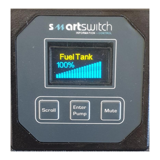
- Page 1 TD-1000 Tank Monitor Installation Manual...
- Page 2 Outputs Pump Output (4 Amps @ 12vdc) The TD-1000 has one output, which can be used to control an interposing relay for a pump such as a waste tank discharge pump. An auto-off feature is standard and is particularly helpful in preventing damage caused by a pump running dry. The auto-off point is programmable.
- Page 3 TD-1000 Wiring Connector Black = Battery - Red = Battery + Green = Sensor In Purple = Sensor + White = Output + Black = Sensor - Blue = Buzzer + Black = Buzzer - Mounting Drill a hole using a 50mm hole saw...
- Page 4 Pump Circuit Connection Relay White BATTERY TO PUMP Toilet Disable Connection Relay Toilet Pump Blue wire Toilet Pump Toilet Disable Connected to SmartSwitch Toilet controller (connect blue output wire to SmartSwitch STS-220 toilet controller as shown) STS-220 Blue wire Tank Full Switch...
-
Page 5: Programming Instructions
Programming Instructions Step 1: Placing the unit in Program Mode Press and hold down the Scroll key now press and hold the Mute key. Hold together for 3 seconds. SET-UP MENU Program Tank Calibrate Set Alarm More Push the Enter/Pump button to select the tank Name or scroll to another function Step 2: Selecting Tank Name The display will now show: SET-UP... - Page 6 Step 4: Audible Alarm On /Off (default is On) The display will now show: Alarm On/Off Press the Enter Key, if the Alarm is On this will turn it Off if its Off this will turn it On Step 5: Pump Off The display will now show: Set Pump Off The Pump Off point is the point where the Pump will turn Off.
-
Page 7: Sensor Installation
PLEASE NOTE: For sensor Model SEN-250 The Maximum Tank Height is 2.5 Meter The maximum surge and safe pressure is 28psi. For more information see “Calibration Tips & Tricks” on our web site www.smartswitch.co.nz Mounting Adaptors Available: A range of mounting adaptors are available which includes flat sidewall, top mount, 1.5” pipe, 2” pipe, 3” pipe and drain valve. - Page 8 Sensor Programming Instructions Press and hold down the Scroll key now press and hold the Mute key. Hold together for 3 seconds. This will bring you to the Set-Up Menu. SET-UP MENU Program Tank Calibrate Set Alarm More Use the Scroll or Backlight key to scroll to “Calibrate” and press the ENTER Key. This will bring you to the Calibrate Menu.
- Page 9 The display will show “Setting Level Please Wait”. If no fluid is added the display will show: The High Level is not greater than the Low level For more information see “Calibration Tips & Tricks” on our web site www.smartswitch.co.nz...
- Page 10 5 Point Calibration: (Bottom, ¼, ½, ¾ & Top) Tank High Point 3/4 Point Half Point 1/4 Point Low Point The display will show: Voltage from Sensor (see table 1 page 19) Low Level Input = ??????? V Fill the tank to the required TANK LOW LEVEL, minimum suggested is liquid just covering the sensor. Wait for approx.
- Page 11 These voltages will be displayed during the calibration setup. Reason: Should the TD-1000 ever need to be replaced the tank will need to be re-calibrated, but if table 1 has been filled out then creating these input voltages using a potentiometer can be done without the tank sender connected, making the process very simple.
- Page 12 © All technologies, design and Intellectual Property is owned by Penguin Electronics Ltd Po Box 272, Waikanae, New Zealand Ph: 0064-4 293-4201 Fax: 0064-4 293-4201 Mobile: 0064-274-919-805 Email: info@smartswitch.co.nz Web: www.smartswitch.co.nz...
Need help?
Do you have a question about the TD-1000 and is the answer not in the manual?
Questions and answers