
Related Manuals for DIGISYSTEM AFV2000


Summary of Contents for DIGISYSTEM AFV2000
- Page 1 NSTRUCTION MANUAL VARIABLE FREQUENCY VIBRATORS POWER SUPPLY AFV2000 : AP020201-APN20201-APS20201 ORDERING CODE filename: AP020201_eng update: 09/11/2012...
-
Page 2: Table Of Contents
INDEX INTRODUCTION ............................2 DEVICE DESCRIPTION ..........................3 TECHNICAL SPECIFICATIONS ........................4 WIRING TABLE ............................5 STARTUP ...............................6 PROBLEMS SOLUTION ..........................7 OPENING INSTRUCTIONS.........................7 PARTS IDENTIFICATION...........................8 OPTION'S WIRING TABLE.........................9 INTRODUCTION The vibrators power supply has been designed to keep in vibration the feeded system giving it the necessary energy exactly when required. -
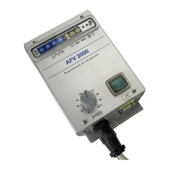
Page 3: Device Description
DEVICE DESCRIPTION Using a variable frequency power supply the optimisation of the vibrating system may result very easy because the natural frequency of the controlled device can be easily tuned. Because this tuning may be executed with system running, in few minutes the optimal frequency may be found. -
Page 4: Technical Specifications
TECHNICAL SPECIFICATIONS Power supply: 230Vac ± 15%, frequency 50 or 60 Hz Output voltage: from 50 to 220Vca (with power supply 230Vca) Output compensation: compensation of power supply variations Output frequency: from 3,0 to 199,9 Hz in step of 0,1 Hz Current: maximum current 5 Amperes peak (about 2,5 Arms) limited from a circuit with autoreset... -
Page 5: Wiring Table
WIRING TABLE PIN REF. SIGNAL DESCRIPTION WIRE WIRE CONNECT TO: SECTION COLOR GROUND CONNECTION YELLOW-GREEN EARTH M3-6 MAINS INPUT (NEUTRAL) BLUE or 230 Vac M3-5 WHITE MAINS INPUT (PHASE) BROWN 230 Vac M3-4 GROUND CONNECTION VIBRATOR D2-T MECHANICAL shielded OUTPU SUPPLY FOR VIBRATOR VIBRATOR COIL D2-1 shielded... -
Page 6: Startup
STARTUP • Verify that mains breaker I1 is in OFF position • Put the potentiometer P3 at about 20% • Verify switch SW2 (red) lever status (if is up the power supply will start as soon as supplied, if is down the external start command is required) •... -
Page 7: Problems Solution
If actions remarked on the table doesn't resolve the problem you may contact factory digisystem srl (e-mail ) we will help you. info@digisystemsrl.it OPENING INSTRUCTIONS As on the electronic card there are some capacitors with high voltage applied (presence of residuary energy, danger of strike) you must wait at least 4 - 5 minutes after the device is disconnected from the power supply, before opening the box. -
Page 8: Parts Identification
PARTS IDENTIFICATION: PART REF. FUNCTION Fairlead Mains input 230Vac access to M3 Fairlead Load output access to M3 Fairlead Start-stop command access to M2 Mains switch Breaker Lamp Mains lamp Fuses Mains fuses Trimmer Sets minimum reference voltage from potentiometer Trimmer Sets maximum reference voltage from potentiometer Potentiometer 10K... -
Page 9: Option's Wiring Table
OPTIONS WIRING TABLE (M2) REF. SIGNAL DESCRIPTION POT. Wire mmq M2-8 Voltage reference (0-5v) Ref.(0÷5V) M2-7 Potentiometer cursor Cursor M2-6 Potentiometer minimum 0V Plc M2-5 Potentiometer maximum No connect. M2-4 0V insulated for remote commands M2-3 Remote start command (PNP or NPN) M2-2 Output power supply OK (PNP) M2-1 +18V insulated for remote commands If voltage reference is coming from potentiometer 10K located on front panel, the...
Need help?
Do you have a question about the AFV2000 and is the answer not in the manual?
Questions and answers