Table of Contents
Troubleshooting

Related Manuals for Broadcast Electronics FX-50

Summary of Contents for Broadcast Electronics FX-50
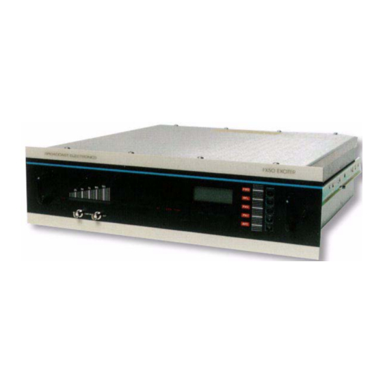
- Page 1 Broadcast Electronics 4100 North 24 Street, Quincy, Illinois 62305 USA • Phone (217) 224-9600 • Fax (217) 224-9607 • www.bdcast.com • bdcast@bdcast.com FX-50, FX-50E 50 WATT FM Exciter Instruction Manual 597-1050 Rev B December 15, 2011...
- Page 2 The information in this publication is subject to improvement and change without notice. Although every effort is made to ensure the accuracy of the information in this manual, Broadcast Electronics accepts no responsibility for any errors or omissions. Broadcast Electronics reserves the right to modify and improve the design and specifications of the equipment in this manual without notice.
- Page 3 The warranty shall be voided if the product or subassembly is equipped with a tamper seal and that tamper seal is broken. BE shall not be liable for any expense of any nature whatsoever incurred by the original user without prior written consent of BE. ©2011 Broadcast Electronics...
- Page 4 NO OTHER WARRANTIES, OR ANY AFFIRMATIONS OF FACT OR PROMISES BY BE, WITH REFERENCE TO THE EQUIPMENT, OR TO MERCHANTABILITY, FITNESS FOR A PARTICULAR APPLICATION, SIGNAL COVERAGE, INFRINGEMENT, OR OTHERWISE, WHICH EXTEND BEYOND THE DESCRIPTION OF THE EQUIPMENT ON THE FACE HEREOF. ©2011 Broadcast Electronics...
- Page 5 RF PRODUCT TECHNICAL ASSISTANCE, REPAIR SERVICE, PARTS - Technical assistance is available from Broadcast Electronics by letter, prepaid telephone or E-mail. Equipment requiring repair or overhaul should be sent by common carrier, prepaid, insured, and well protected.
- Page 6 All returned merchandise must be sent freight prepaid and properly insured by the customer. MODIFICATIONS - Broadcast Electronics, reserves the right to modify the design and specifications of the equipment in this manual without notice. Any modifications shall not adversely affect performance of the equipment so modified.
- Page 7 Additional information follows. D. RF BURNS Circuit boards with RF power transistors contain high RF potentials. Do not operate an RF power module with the cover removed. ©2011 Broadcast Electronics...
- Page 8 The power components in the transmitter are cooled by forced-air and natural convection. When handling any components of the transmitter after it has been in operation, caution must always be taken to ensure that the component is cool enough to handle without injury. ©2011 Broadcast Electronics...
-
Page 9: Table Of Contents
Table of Contents OVERVIEW............................1 1.1 RELATED PUBLICATIONS........................1 1.2 EQUIPMENT DESCRIPTION........................ 1 1.3 FX-50 AND FX-50E MODELS......................2 1.4 PHYSICAL DESCRIPTION........................2 1.5 ELECTRICAL DESCRIPTION........................ 2 1.6 EQUIPMENT SPECIFICATIONS......................3 INSTALLATION ..........................7 2.1 UNPACKING. - Page 10 10.3 REMOVAL AND INSTALLATION ....................... 74 10.4 THEORY OF OPERATION ......................... 75 10.5 MAINTENANCE ..........................78 10.6 TROUBLESHOOTING........................82 11 SYNCHRONOUS FM BOOSTER ....................... 84 11.1 SYSTEM DESCRIPTION........................84 11.2 SYSTEM CONFIGURATIONS......................84 11.3 ELECTRICAL SPECIFICATIONS......................84 ©2011 Broadcast Electronics...
- Page 11 11.4 INSTALLATION ..........................85 11.5 INSTALLATION ADJUSTMENTS......................86 11.6 THEORY OF OPERATION ......................... 86 11.7 MAINTENANCE ..........................90 12 BE Part Numbers .......................... 94 13 RF Technical Services Contact Information ................148 14 Drawings…..........................148 ©2011 Broadcast Electronics...
- Page 12 This page intentionally left blank ©2011 Broadcast Electronics...
-
Page 13: Overview
- 1 - OVERVIEW Information presented by this section provides a general description of the FX-50/E FM Exciter features and lists equipment specifications. RELATED PUBLICATIONS. The following list of publications provides data for equipment and options associated with the FX-50/E FM Exciters. -
Page 14: Fx-50 And Fx-50E Models
(unbalanced). PHYSICAL DESCRIPTION. The FX-50/E chassis is equipped with slide rails to allow easy access to all assemblies when the unit is extended from the rack. Removal and installation of assemblies within the exciter is facilitated by the semimodular mechanical construction. Each assembly is firmly mounted to the main chassis and electrically connected to the main wiring harness with plugs and jacks. -
Page 15: Equipment Specifications
1.5.2 STATUS DISPLAYS. The FX-50/E exciters are designed with front-panel LEDs to indicate the status of three main exciter operating potentials, three preset limits, and operating frequency stabilization. Additional LEDs are incorporated on the AFC/PLL circuit board assembly to indicate the status of operating potentials and monitor reference oscillator and modulated oscillator circuit conditions. - Page 16 0.005% or Less (0.003% Typical) at 400 Hz. DISTORTION PLUS NOISE COMPOSITE SMPTE INTER- 0.005% or Less (0.003% Typical), MODULATION DISTORTION 60 Hz/7 kHz 1:1 ratio. COMPOSITE TRANSIENT IMD 0.01% or Less (Square Wave/Sine Wave.) COMPOSITE AMPLITUDE +0.025 dB, 30 Hz to 53 kHz. ©2011 Broadcast Electronics...
- Page 17 90 dB Below +75 kHz Deviation @ 400 Hz (93 dB Typical) Measured in a 20 Hz to 15 kHz Bandwidth with 75 Microsecond Deemphasis. 94 dB (96 dB Typical) with A weighting. REGULATORY FX-50E ONLY Meets CE Specifications. ©2011 Broadcast Electronics...
- Page 18 WIDTH 17.70 Inches (44.9 cm). DEPTH 19.00 Inches (48.3 cm). ENVIRONMENTAL AMBIENT OPERATING +32˚F to +122˚F (0˚C to +50˚C) Operational to -20˚C. TEMPERATURE HUMIDITY 95% Maximum, Non-Condensing ALTITUDE 0 to 15,000 Feet (4572 m) Above Sea Level. ©2011 Broadcast Electronics...
-
Page 19: Installation
The FX-50E can only operate from a 240V ac supply. Therefore, ensure the line voltage selector is configured to 240V. For FX-50 models, the unit can be operated from a 110V or 220V ac supply. Check the ac line voltage programming as follows: Place the exciter on a work surface. - Page 20 Figure 2-1. FX-50/E REAR-PANEL CONNECTIONS (SHEET 1 OR 2) ©2011 Broadcast Electronics...
- Page 21 Figure 2-1. FX-50/E REAR-PANEL CONNECTIONS (SHEET 2 OR 2) ©2011 Broadcast Electronics...
- Page 22 POS-MUTE-NEG switch S3 on the power supply/control circuit board is provided to select the RF mute input logic polarity (refer to Figure 2-2). S3 must be in the POS position when the FX-50/E is operated with a Broadcast Electronics transmitter or as a stand-alone unit. Switch S3 is factory operated to the POS position prior to shipping.
- Page 23 GAIN SELECTION. The gain of the balanced monophonic audio processing circuit on the AFC/PLL circuit board is selectable for input levels ranging from 0.0 dB to +10 dB. The FX-50/E is shipped from the factory for an input level of +10 dB. If an alternate level is required, refer to Figure 2-3 and connect the appropriate resistor...
-
Page 24: Wiring
GROUND. Ensure a ground wire is connected from terminal 4 of the exciter rear-panel terminal board to earth ground. REMOTE CONTROL. The FX-50/E exciters are designed for remote control operation (refer to Figure 2-1). The exciter will interface with almost any remote control unit or panel. The following text presents a description of the remote control and indicator functions. - Page 25 The relay contacts are rated at 125V @ .5 Amps and are located at J2-1, J2-2, and J2-3 on FX-50 units and J1-1, J1-2, and J1-3 on FX-50E units.
-
Page 26: Exciter Checkout
CONNECTION OF COMPOSITE STEREO SIGNAL SOURCES. The FX-50 is equipped with one balanced and one unbalanced composite input on the rear-panel (COMPOSITE INPUT BAL and UNBAL). The FX-50E is equipped with a single unbalanced composite input (COMPOSITE INPUT UNBAL). These inputs are for the connection to a composite stereo source such as a stereo generator or composite STL receiver (refer to Figure 2-1). - Page 27 Disconnect the RF load and connect the exciter output to the transmitter RF input connector. LOW-PASS FILTER INSTALLATION. The FX-50/E can be equipped with an optional low-pass filter to allow the unit to operate as a low power transmitter. The optional low-pass filter is installed as follows.
- Page 28 Figure 2-4. LOW-PASS FILTER INSTALLATION REMOTE EXCITER CONNECTIONS. The following text provides information required to connect a remote FX-50/E exciter to a tube-type B/T series FM transmitter. The exciter interface cable is stored in the transmitter cabinet for shipment. Refer to Table 2-1 and connect the cable to the exciter rear-panel as described.
-
Page 29: Operation
OF ANY DISCREPANCIES. 3.2.1 TURN ON. Primary power will be applied to the FX-50/E when the transmitter filament supply is energized. Operate the transmitter filament power to ON. The following events will occur: A. The flushing fan will operate. B. The +20V, -20V, and +5V operating voltage status indicators will immediately illuminate. - Page 30 Table 3-1. FX-50/E CONTROL AND INDICATORS ITEM NOMENCLATURE FUNCTION RF Power Output Level Adjusts exciter RF output level. CW adjustment increases Control output level. +20V Status Indicator Illuminates to indicate the presence of the +20 volt operating potential. -20V Status Indicator Illuminates to indicate the presence of the -20 volt operating potential.
- Page 31 Table 3-2. POWER/VSWR CONVERSION VSWR Reflected Power in Watts = POWER RATIO Forward Power in Watts 0.000 1.0:1 0.002 1.1:1 0.008 1.2:1 0.017 1.3:1 0.028 1.4:1 0.040 1.5:1 0.053 1.6:1 0.074 1.75:1 0.111 2.0:1 0.183 2.5:1 0.250 3.0:1 0.360 4.0:1 ©2011 Broadcast Electronics...
- Page 32 Figure 3-1. FX-50/E CONTROLS AND INDICATORS ©2011 Broadcast Electronics...
-
Page 33: Theory Of Operation
This section presents overall theory of operation for the FX-50/E FM Exciters. For the purpose of definition, the FX-50/E Exciter is divided into functional subassemblies in the following text. A detailed description of each subassembly is presented in Part II of this manual. A block diagram of the FX- 50/E FM Exciter is presented in Figure 4-1. - Page 34 REMOTE CONTROL/STATUS INTERFACING AND RFI FILTER NETWORK. Remote control and status interfacing is accomplished by: 1) an interface circuit board on FX-50 models and 2) a 25-pin D-Type connector on the RFI filter circuit board for FX-50E models. The RFI filter circuit board prevents interference from signals of 500 kHz and above by filtering and bypassing the audio, control, and status input and output circuits.
- Page 35 Figure 4-1. FX-50/E OVERALL SIMPLIFIED SCHEMATIC ©2011 Broadcast Electronics...
- Page 36 The broadband characteristics of the amplifier eliminates the necessity for adjustments for any frequency within the FM band, assures that the exciter output is transparent to the signal generated by the modulated oscillator, and enhances amplifier stability under varying load conditions. ©2011 Broadcast Electronics...
-
Page 37: Maintenance
Check performance levels by utilizing the multimeter functions and status indicators provided. SECOND LEVEL MAINTENANCE. Second level maintenance consists of procedures required to restore the FX-50/E to operation after a fault has occurred. The maintenance philosophy of the FX-50/E FM Exciters consists of problem isolation to a specific assembly. -
Page 38: Troubleshooting
G. Control Circuit H. Exciter Output DC VOLTMETER. The FX-50/E is equipped with a high impedance voltmeter which can be employed to measure internal dc potentials. To convert the front-panel multimeter to a dc test instrument, refer to Figure 5-1 and the following procedure. - Page 39 0.55 Ampere 10 W 230 V AC 0.50 Ampere 50 W 115 V AC 1.40 Ampere 30 W 115 V AC 1.20 Ampere 20 W 115 V AC 1.10 Ampere 10 W 115 V AC 1.00 Ampere ©2011 Broadcast Electronics...
- Page 40 Figure 5-1. FX-50/E ASSEMBLY ©2011 Broadcast Electronics...
- Page 41 MANUFACTURER. USE CARE IN REPLACING TRANSISTORS OF THIS TYPE. COMPONENT REPLACEMENT. The circuit boards used in the FX-50/E exciters are double-sided boards with plated-through holes. Because of the plated-through holes, solder fills the holes by capillary action. These conditions require that defective components be removed carefully to avoid damage to the board.
- Page 42 B. MODULATION CALIBRATION procedure in the AFC/PLL section of this manual. C. MODULATION CORRECTION procedure in the AFC/PLL section of this manual. D. FWD CAL (R5) AND RFL CAL (R9) procedure in the POWER SUPPLY/CONTROL section of this manual. ©2011 Broadcast Electronics...
-
Page 43: Power Supply/Control Circuit
FWD POWER +11.45V at 10 K Ohm for 50W RF RFL POWER Approximately +1V at 10K Ohm for 2W RF TEMP OL DRIVE +18V at 5 mA, Maximum PA Voltage Approximately +20.8V at 3.25 Amperes for 50W ©2011 Broadcast Electronics... -
Page 44: Removal And Installation
Refer to Figure 6-1 as required for a description of the following circuits. A. RF Mute Circuit B. Forward/Reflected Amplifier Circuits C. Temperature Sense Circuit D. Open Fuse Detector Circuit E. Power Control Circuit ©2011 Broadcast Electronics... - Page 45 R9. The output of U1B is routed to: 1) diodes D1 and D2, 2) the metering circuit board for display, and 3) the rear-panel barrier strip for remote metering. ©2011 Broadcast Electronics...
- Page 46 Figure 6-1. CONTROL CIRCUITRY SIMPLIFIED SCHEMATIC ©2011 Broadcast Electronics...
- Page 47 With the AUTO/MAN switch in the manual position, only the reflected voltage sample at U1B is connected to the input of U4 through D2 to provide proportional VSWR foldback. In addition, resistor R47 is shunted to decrease the gain of U4. ©2011 Broadcast Electronics...
- Page 48 Primary power is applied to the FX-50/E through an RFI filter and ac receptacle module. On FX-50E models, the ac line routed through an additional ac line filter. This filter alows the FX-50E to meet CE ac line specifications.
- Page 49 Figure 6-2. POWER SUPPLY SIMPLIFIED SCHEMATIC DIAGRAM ©2011 Broadcast Electronics...
-
Page 50: Maintenance
C. Connect a 100 watt, 50 Ohm test load and in-line wattmeter to the rear-panel RF OUTPUT receptacle. D. Remove the top-cover. Refer to Figure 6-3 and operate AUTO-PWR-MAN switch S1 to the MAN position. E. Apply primary power and operate the exciter. ©2011 Broadcast Electronics... - Page 51 DONOT TOUCH ANY COMPONENT WITHIN THE EXCITER WITH POWER APPLIED. WARNING J. Depress the RFL meter function switch. Refer to Figure 6-3 and adjust RFL CAL control R9 until the meter indicates 11% of the value recorded in step I. ©2011 Broadcast Electronics...
- Page 52 D. Using the following equation and information from step C, calculate and record the voltage (V). V = TI + 273 E. Refer to Figure 6-3 and connect a voltmeter between TP1 and TP6 (ground). F. Apply primary power to the exciter. ©2011 Broadcast Electronics...
- Page 53 Figure 6-4. PARALLEL LOAD CONNECTION ©2011 Broadcast Electronics...
- Page 54 D. Refer to Figure 6-3 and adjust R27 until the voltmeter indicates +3.65V dc. WARNING DISCONNECT EXCITER PRIMARY POWER BEFORE PROCEEDING. WARNING E. Disconnect the primary power to the exciter. F. Remove the test equipment and replace the top-cover. ©2011 Broadcast Electronics...
- Page 55 After the problem is isolated and power is totally deenergized, refer to the schematic diagrams and the theory of operation to facilitate in problem resolution. The defective circuitry may be repaired locally or the circuit board may be returned to Broadcast Electronics. for repair or replacement. ©2011 Broadcast Electronics...
- Page 56 Figure 6-5. NO PA VOLTAGE TO THE RF AMPLIFIER ©2011 Broadcast Electronics...
-
Page 57: Exciter Metering Circuit Board
The internal voltmeter input impedance is 1.5 Meg Ohms. The meter is capable of measuring dc potentials from 0 to ±45 volts. REMOVAL AND INSTALLATION This section provides removal and installation procedures for the FX-50/E metering circuit board assembly. 7.3.1 REMOVAL PROCEDURE. - Page 58 Figure 7-1. METERING CIRCUIT REMOVAL AND INSTALLATION DIAGRAM ©2011 Broadcast Electronics...
-
Page 59: Theory Of Operation
A. Disconnect the primary power from the exciter. B. Follow the REMOVAL PROCEDURE in reverse order. THEORY OF OPERATION This section presents the theory of operation for the FX-50/E metering circuit board. 7.4.1 FUNCTIONAL DESCRIPTION. The metering circuit board contains four circuits. A simplified schematic diagram of the metering circuit board is presented in Figure 7-2. - Page 60 Figure 7-2. METTERING BOARD SIMPLIFIED SCHEMATIC ©2011 Broadcast Electronics...
- Page 61 The output lines of the display drivers are connected to LED displays DS9, DS10, and DS11 which illuminate when the lines are activated. An output line from U20 is routed to one shot U18 which generates a one second pulse to illuminate the 100% LED. ©2011 Broadcast Electronics...
-
Page 62: Maintenance
7.4.5 VOLTAGE REGULATOR CIRCUITS. The metering circuit board contains four voltage regulator circuits which convert the FX-50/E primary operating voltages to potentials required for circuit board operation. All regulators are equipped with overload protection, thermal overload protection, and current limiting circuits. - Page 63 A. Remove the top-cover and connect an audio generator to the front-panel COMPOSITE IN connector. B. Connect an oscilloscope to the front-panel COMPOSITE OUT connector. C. Adjust the audio generator for 400 Hz at 6 volts peak-to-peak (2.12V RMS) as indicated on the oscilloscope. ©2011 Broadcast Electronics...
- Page 64 After the problem is isolated and power is totally deenergized, refer to the schematic diagrams and the theory of operation to facilitate in problem resolution. The defective circuitry may be repaired locally or the circuit board may be returned to Broadcast Electronics for repair or replacement. Table 7-1. METERING CIRCUIT BOARD TROUBLESHOOTING...
- Page 65 NO FWD POWER METER INDICATION 1. Check input switch U6A. NO FWD AND RFL POWER METER 2. Check integrated circuit U4A and associated INDICATION components. 1. Check integrated circuit U7. NO LCD DISPLAY 2. Check display DS12. ©2011 Broadcast Electronics...
-
Page 66: Modulated Oscillator
D. Remove the four screws securing the modulated oscillator assembly to the steel mounting plate. Remove the ground straps. 8.3.2 INSTALLATION PROCEDURE. To install the modulated oscillator assembly after repairs have been completed, proceed as follows: ©2011 Broadcast Electronics... -
Page 67: Theory Of Operation
R23 and R24 which establish a 50 Ohm output impedance. Two identical signals are output from the modulated oscillator assembly. The signal at R24 provides drive to the RF amplifier and the signal at R23 provides a frequency sample to the AFC/PLL circuit board. ©2011 Broadcast Electronics... - Page 68 Figure 8-1. MODULATED OSCILLATOR SIMPLIFIED SCHEMATIC DIAGRAM ©2011 Broadcast Electronics...
-
Page 69: Maintenance
The modulated oscillator assembly contains no controls which require adjustment or calibration. TROUBLESHOOTING. Field servicing the modulated oscillator assembly is not recommended. Therefore, if difficulties are encountered and the modulated oscillator is suspected as faulty, return the assembly to Broadcast Electronics Inc. for repair or replacement. ©2011 Broadcast Electronics... -
Page 70: Afc/Pll
+2.0V DC to 9.0V DC, Dependent Upon RF Center Frequency. AFC INTERLOCK Open Collector Output. EXTERNAL LOCK INDICATOR Open Collector Output. COMPOSITE AUDIO (Metering) 6.0V p-p at 1 k Ohm. COMPOSITE TEST 6.0V p-p at 1 k Ohm. ©2011 Broadcast Electronics... -
Page 71: Removal And Installation
The AFC/PLL circuit board contains nine circuits. Figure 9-1 presents a simplified schematic of the AFC/PLL circuit board. Refer to Figure 9-1 as required for a description of the following circuits. A. Reference Divider Circuit B. Reference Oscillator Activity Monitor C. RF Sample Divider Circuit D. Comparator Circuit E. Loop Filter Control Circuit ©2011 Broadcast Electronics... - Page 72 U10B biases integrator/amplifier U11B at 2.5V to provide a voltage gain of 11 for any differential voltage within the range of the bias. The output of U11B is applied to the metering circuit board for display. ©2011 Broadcast Electronics...
- Page 73 LDR1 will shunt the 5 Hz lowpass filter and route the output from U11B directly to U11A. LDR2 will shunt resistor R31 to rapidly charge capacitor C35 through resistor R34. Modulation coupling capacitor C37 will be rapidly charged through LDR3. ©2011 Broadcast Electronics...
- Page 74 Figure 9-1. AFC/PLL CIRCUIT BOARD SIMPLIFIED SCHEMATIC ©2011 Broadcast Electronics...
- Page 75 BALANCED INPUTS. A balanced composite audio input circuit and a balanced mono phonic audio input circuit are provided by the FX-50 exciter. Audio for the composite circuit is input through a rear-panel BNC connector. Audio for the monophonic circuit is in put through rear-panel barrier strip TB1.
-
Page 76: Maintenance
WARNING A. Disconnect the exciter primary power. B. Remove the top-cover and connect an audio generator to the AUDIO INPUT terminals on rear-panel barrier strip TB1. C. Connect a digital voltmeter to the front-panel COMPOSITE OUT receptacle. ©2011 Broadcast Electronics... - Page 77 DISCONNECT EXCITER PRIMARY POWER BEFORE PROCEEDING. WARNING A. Disconnect the exciter primary power. B. Remove the top-cover and connect an audio generator to the rear-panel BAL COMPOSITE INPUT receptacle. C. Connect a digital voltmeter to the front-panel COMPOSITE OUT receptacle. ©2011 Broadcast Electronics...
- Page 78 MODULATION CORRECTION control R63 is adjusted as follows. Procedure. To adjust MODULATION CORRECTION control R63, refer to Figure 9-2 as required and proceed as follows: WARNING DISCONNECT EXCITER PRIMARY POWER BEFORE PROCEEDING. WARNING A. Disconnect the exciter primary power. ©2011 Broadcast Electronics...
- Page 79 The REF OSC FREQ TRIM control on the AFC/PLL circuit board adjusts the reference frequency. The REF OSC FREQ TRIM control is adjusted as follows. Procedure. To adjust the REF OSC FREQ TRIM control, refer to Figure 9-2 as required and proceed as follows: ©2011 Broadcast Electronics...
- Page 80 Table 4-1 lists standard carrier frequencies and corresponding switch binary codes for domestic and European operation. A ”1” in the code represents a switch in the ON position and a “0” represents a switch in the OFF position. S1, S2, and S3 are programmed as follows. Figure 9-3. FREQUENCY SELECTION ©2011 Broadcast Electronics...
- Page 81 Table 9-2. FREQUENCY SYNTHESIZER PROGRAMMING ©2011 Broadcast Electronics...
-
Page 82: Troubleshooting
D. Replace the top-cover and return the exciter to service. 9.7.8 LOW-PASS FILTER. An optional low-pass filter can be installed on the FX-50/E exciter rear-panel for stand-alone operation. Due to critical tuning parameters, field adjustment is not recommended. If adjustment is necessary, contact Broadcast Electronics field service for assistance. - Page 83 After the problem is isolated and power is totally deenergized, refer to the schematic diagrams and the theory of operation to assist in problem resolution. The defective circuitry may be repaired locally or the circuit board may be returned to Broadcast Electronics for repair or replacement. ©2011 Broadcast Electronics...
- Page 84 Figure 9-4. NO RF OUTPUT-LOCK IS EXTINGUISHED. ©2011 Broadcast Electronics...
- Page 85 Figure 9-5. NO MODULATION, LOCK INDICATOR ILLUMINATED. ©2011 Broadcast Electronics...
-
Page 86: 10 Rf Amplifier
To remove the RF amplifier assembly, proceed as follows: WARNING DISCONNECT EXCITER PRIMARY POWER BEFORE PROCEEDING. WARNING A. Disconnect the primary power from the exciter. B. Remove the exciter top-cover and disconnect J15 from P15 of the RF amplifier power/control cable. ©2011 Broadcast Electronics... -
Page 87: Theory Of Operation
Input Amplifier. The input amplifier consists of thick-film hybrid amplifier U2, and resistor pad R6 and R7. A 1 milliwatt RF input signal from the modulated oscillator is input to U2. This stage provides approximately 1 watt of output power across R6 and R7 to the following stage. ©2011 Broadcast Electronics... - Page 88 R10, and PA bias control R17. The matching network converts the output impedance of Q3 to the low input impedance required by Q4. R10 provides isolation from the bias network and R17 establishes the quiescent drain current for Q4. This stage provides 50 watts of output power to the associated transmitter. ©2011 Broadcast Electronics...
- Page 89 Figure 10-1. RF AMPLIFIER SIMPLIFIED SCHEMATIC. ©2011 Broadcast Electronics...
-
Page 90: Maintenance
E. Coaxial accessory cable, BNC connectors, shipped with exciter (P/N 947-0017-2). 10.5.2 RFL NULL (R12). The RFL NULL control on the RF amplifier circuit board adjusts the directivity of the reflected power directional coupler. Potentiometer R12 is adjusted as follows. ©2011 Broadcast Electronics... - Page 91 H. Remove all test equipment and replace the access hole plug and exciter top-cover. 10.5.3 PA BIAS (R17). PA BIAS control R17 on the RF amplifier circuit board adjusts the PA quiescent current. Potentiometer R17 is adjusted as follows. Procedure. To adjust PA bias control R17, proceed as follows: ©2011 Broadcast Electronics...
- Page 92 Figure 10-2. RF AMPLIFIER CIRCUIT BOARD CONTROLS. ©2011 Broadcast Electronics...
- Page 93 O. Disconnect primary power to the exciter. P. Remove all test equipment and replace the RF amplifier assembly mounting bracket/shield. Q. Refer to the INSTALLATION PROCEDURE in SECTION II, REMOVAL AND INSTALLATION and install the RF amplifier assembly in the exciter chassis. ©2011 Broadcast Electronics...
-
Page 94: Troubleshooting
After the problem is isolated and power is totally deenergized, refer to the schematic diagrams and the theory of operation to facilitate in problem resolution. The defective circuitry may be repaired locally or the circuit board may be returned to Broadcast Electronics for repair or replacement. ©2011 Broadcast Electronics... - Page 95 Figure 10-3. RF AMPLIFIER TROUBLESHOOTING INFORMATION. ©2011 Broadcast Electronics...
-
Page 96: 11 Synchronous Fm Booster
The synchronous FM booster system is designed to provide precise and reliable frequency locking of one or more slave FX-50/E exciters to a master FX-50/E exciter. The system features a plug-in circuit board installed in the master exciter which generates a reference signal. This signal is transmitted to a similar circuit board installed in the slave exciter at the booster site to synchronize a 10 MHz voltage controlled crystal oscillator (VCXO). - Page 97 Unlocked from Master, 0˚ to 50˚C. 11.4 INSTALLATION This section contains information required for installation of the Broadcast Electronics synchronous FM booster system. This procedure is specifically for field installation kits. To install the master or slave circuit board, refer to the following information and sheet 2 of assembly drawing AC909-0131 in SECTION VI, DRAWINGS, as required.
- Page 98 BEFORE PROCEEDING. WARNING Disconnect the exciter primary power. Remove the top-cover and connect a 600 Ohm load and oscilloscope to the FX-50 rear panel SUB-1 connector. Apply primary power to the exciter. WARNING DO NOT TOUCH ANY COMPONENT WITHIN THE EXCITER WITH POWER APPLIED.
- Page 99 50% duty cycle. This pulse is applied to input amplifier U7 through programmable jumper J4. Finally, the output of U7 is applied to amplifier U8 through a band pass filter and level control R26. ©2011 Broadcast Electronics...
- Page 100 Figure 11-1. SLAVE FM BOOSTER SIMPLIIFED SCHEMATIC. ©2011 Broadcast Electronics...
- Page 101 Figure 11-2. MASTER FM BOOSTER SIMPLIFIED SCHEMATIC. ©2011 Broadcast Electronics...
- Page 102 F. Remove the test equipment and replace the top-cover. 11.7.2 LOW PASS FILTER (L1, L2, L3). Inductors L1, L2, and L3 on the slave or master circuit board adjust the sensitivity of the low-pass filter network. Inductors L1, L2, and L3 are adjusted as follows. ©2011 Broadcast Electronics...
- Page 103 E. Apply primary power to the exciter. WARNING DO NOT TOUCH ANY COMPONENT WITHIN THE EXCITER WITH POWER APPLIED. WARNING F. Refer to Figure 11-3 and adjust L1, L2, and L3 for a maximum indication on the oscilloscope. Repeat if necessary. ©2011 Broadcast Electronics...
- Page 104 11.7.4 REFERENCE FREQUENCY SELECTION. The removal or installation of capacitors C25, C26, and C29 selects alternate reference frequencies. If an alternate frequency is desired, refer to Figure 11-3 and the following information and install the required combination of capacitors. ©2011 Broadcast Electronics...
- Page 105 REFERENCE FREQUENCY 125 kHz Removed Removed Removed 100 kHz Installed Installed Removed 90.909 kHz Installed Installed Installed ©2011 Broadcast Electronics...
-
Page 106: 12 Be Part Numbers
12 BE Part Numbers This section provides parts lists for the FX-50/E Exciter. The parts lists provide descriptions and part numbers of electrical components, assemblies, and selected mechanical parts required for maintenance. Each parts list entry in this section is indexed by reference designators appearing on the applicable schematic diagrams. - Page 107 6-32 S.S. HEX THIN NUT 421-6008 6-32 KEP NUT 421-8001 8-32 S.S. HEX NUT 421-8028 NUT,JAM,1/2-28 UNEF-2B 422-6106 SCREW,SEMS 6-32 X 3/8 PAN PH. ST." 423-0001 WASHER,FLAT,#10 SST,.438 X .203 X .065 423-0003 #10 LOCK INT TOOTH ©2011 Broadcast Electronics...
- Page 108 STRIP,RFI SHIELD ..2 469-0365 FINGER STOCK,1S197520A 2.75 469-0366-1 STRIP,RFI SHIELD 1.25 ..2 469-0366 FINGER STOCK (NOTE!!!!!) 1.25 469-0366-2 STRIP,RFI SHIELD 4.25 ..2 469-0366 FINGER STOCK (NOTE!!!!!) 4.25 471-0360 COVER,AFC/PLL PCB FX50 ..2 471-0360-009 COVER,AFC/PLL PCB UNSCREENED 471-0584-100 COVER,TOP,FM250C/E ©2011 Broadcast Electronics...
- Page 109 PART NO. DESCRIPTION REF. DES. LEVEL 471-0631 SHIELD,XFMR FX50 471-0795 SHIELD,FRONT PANEL PCB,FX-50 ..2 471-0795-009 SHLD,FRT PNL PCB,FX-50,UNSCRND 471-0962-100 PANEL,REAR,FX-50E/FX-50,SCREENED 471-5289-001 BRACKET,FUSE HOLDER,FX50,SCREENED ..2 471-5289 BRACKET,FUSE HOLDER,FX50,FM100,FM250,UNSCREEN 471-6269-300 PANEL,STATUS,FX50,HD COLORS 474-0300 PLATE,MODULATED OSC FX50 486-0004 HANDLE 1 3/4 486-0014 FERRULE,BLK,FOR .25 DIA HANDLE...
- Page 110 R6, R13, R37, R15, R16, R24, R46, R47, R48, R95, R75, R76, R50, R103, R67, ..2 100-1111 RES,118 OHM,1/4W,1% ..2 100-1231 RES,121 OHM,1/4W,1% R21, R97, R99 ..2 100-1551 RES,15K OHM,1/4W,1% R25, R26, R27, R51 ..2 100-1731 RES,174 OHM,1/4W,1% ©2011 Broadcast Electronics...
- Page 111 RES,332 OHM,1/4W,1%,METAL R2, R8 ..2 103-3324 RES,3.32K OHM,1/4W,1%,METAL R4, R5 ..2 103-3631 RES,365 OHM,1/4W,1%,METAL ..2 103-3836 RES,383K OHM,,1/4W,1%,METAL ..2 103-4361 RES,432K OHM,1/4W,1%,METAL ..2 103-4753 RES,475 OHM,1/4W,1%,METAL R45, R61 ..2 103-4755 RES,47.5K OHM,1/4W,1%,METAL ..2 103-4951 RES,49.9K OHM,1/4W,1%,METAL R36, R12 ©2011 Broadcast Electronics...
- Page 112 220-4040 IC,MC14040B 12-BIT BINARY ..2 220-5151 IC,MC145151 SYNTHESIZER ..2 220-8658 IC,SP8658 PRESCALER,DIVIDE/20 ..2 221-0072 AMP,OP,BIFET TLO72CP ..2 221-0358 AMP,DUAL OP,LM358 ..2 221-5532-001 IC,NE-5532AN U10, U14, U15, U16 ..2 226-0392 RES NETWORK, 10K R73, R96 ..2 227-0317 VR,LM317T,LM317KC ©2011 Broadcast Electronics...
- Page 113 SOCKET,8-PIN DIP,BURNDY XU10, XU11, XU13, XU14, XU15, XU16 ..2 417-1404 SOCKET,14-PIN DIP XU1, XU3, XU4 ..2 417-1604 SKT,16-PIN,DIP XU2, XU5, XU12, XR73, XR96 ..2 417-2804 SOCKET,IC 28-PIN,DIP,HI RELIABILITY ..2 420-6104 SCREW,6-32X.250,S.S. PH ..2 423-6002 #6 LOCK SPLIT ©2011 Broadcast Electronics...
- Page 114 C12, C20 ..2 031-1043 CAP,MYLAR FILM,.01UF,100V,RAD C8, C10 ..2 040-5013 CAP,MICA,50PF,500V,5% ..2 042-3922 CAP,MICA,390PF,100V,5% C1, C2, C14, C18, ..2 100-1013 RES,1 OHM,1/4W,5% ..2 100-1031 RES,100 OHM,1/4W,1%,METAL ..2 100-1041 RES,1K OHM,1/4W,1% R6, R73, R61, R37, R12, R50, R59 ©2011 Broadcast Electronics...
- Page 115 R38, R85, R80, R81, R83, R84, R26, R57 ..2 103-5141 RES,5.11K OHM,1/4W,1%,METAL R13, R49 ..2 103-6194 RES,6.19K OHM,1/4W,1%,METAL R17, R19 ..2 103-6346 RES,634K OHM,1/4W,1%,METAL ..2 103-6813 RES,681 OHM,1/4W,1%,METAL ..2 103-6814 RES,6.81K OHM,1/4W,1%,METAL ..2 110-2233 RES,220 OHM,1/2W,5% ..2 132-0114 RES,1.5 OHM,10W,5%,WW ©2011 Broadcast Electronics...
- Page 116 ..2 227-0337 VOLTAGE REGULATOR,3 TERM, NEG ..2 227-0723 IC,VR,UA723 ..2 237-0007 SCR,25A,100V,2N6505 ..2 330-0802 FUSE,FAST ACTING,8A,GBB-8,BUSS ..2 340-0004 SW,JUMPER PROGRAMMABLE ..2 345-0863 SW,SLD,DPDT,SWCFT C56206L2 S1, S2, S3 ..2 360-0003 FERRITE BEAD,.291 DIA ..2 407-0141 COVER,FUSE,STD 840836 RICHCO ©2011 Broadcast Electronics...
- Page 117 C38, C39, C40, C41, C42, C43, C44, C45, C50, C52, C54, C56, C57, C61, C63 ..2 020-1085 CAP,LYTIC,100UF,50V,STDUP,NP ..2 023-1076 CAP,LYTIC,10uF,50V,STDUP C12, C32, C33, C51, C53, C55, C58, C60, ..2 023-1084 CAP,LYTIC,100MFD,35V,STDUP,RAD C46, C47, C48, C49 ..2 024-2274 CAP,LYTIC,22UF,100V,STDUP ©2011 Broadcast Electronics...
- Page 118 R9, R39, R54, ..2 103-1021 RES,10 OHM,1/4W,1%,METAL R33, R34, R36 ..2 103-1062 RES,100K OHM,1/4W,1%,METAL R5, R31, R53, R64, R65, R87, R97, R111 ..2 103-1105 RES,11K OHM,1/4W,1%,METAL ..2 103-1214 RES,1.21K OHM,1/4W,1%,METAL R90, R92, R94 ..2 103-1274 RES,1.27K OHM,1/4W,1%,METAL ©2011 Broadcast Electronics...
- Page 119 R2, R4 ..2 103-6193 RES,619 OHM,1/4W,1%,METAL R72, R73, R74 ..2 103-8254 RES,8.25K OHM,1/4W,1%,METAL ..2 103-8255 RES,82.5K OHM,1/4W,1%,METAL ..2 103-8453 RES,845 OHM,1/4W,1%,METAL R44, R46, R49, R51 ..2 103-8454 RES,8.45K OHM,1/4W,1%,METAL ..2 103-9314 RES,9.31K OHM,1/4W,1%,METAL ..2 177-1054 RES,TRMR,10K,VERT ADJ ©2011 Broadcast Electronics...
- Page 120 U14, U22 ..2 227-0337 VOLTAGE REGULATOR,3 TERM, NEG U15, U16 ..2 228-4028 IC,MC14028B ..2 228-4071 IC,MC14070 QUAD EXCLUSIVE OR ..2 228-4076 IC,MC14076 QUAD REGISTER ..2 228-4532 IC,MC14532B 8-BIT PRIOR ENCOD ..2 228-4538 IC,MC14538B NATL SEMICONDUCTOR ..2 229-0555 IC,TIMER,NE555N ©2011 Broadcast Electronics...
- Page 121 XU19, XU20, XU21 ..2 417-4005 SOCKET,40-PIN,DIP,HIGH RELIABILITY ..2 420-6104 SCREW,6-32X.250,S.S. PH ..2 423-6002 #6 LOCK SPLIT ..2 426-6000 PEM NUT,#6-32 KFS2-632 ..2 449-0006 TEST CLIP,COILED ..2 519-0108 PCB,BLANK,METERING (scan) 919-0445-309 ASSY,PCB,RFI FILTER,CE ..2 417-0039-VLX CONN,BNC,PCB,VERT MOUNT,VALOX REMOVE J305 BODY ©2011 Broadcast Electronics...
- Page 122 R301, R309, ..3 201-0012 ZENER VOLTAGE SUPPRESSOR,+/-12V D310, D311, D312, D313, D314, D315, D316, D317, D318, D319, D320, D321 ..3 201-0027 ZENER VOLTAGE SUPPRESSOR,+/-27V D302, D303, D304, D305 ..3 201-0040 ZENER VOLTAGE SUPPRESSOR,+/-18V D306, D307, D308, D309 ©2011 Broadcast Electronics...
- Page 123 ..3 441-0184 STOFF,6-32,MALE-FEMALE,3/8 ..3 519-0445-001 PCB,MACH,RFI FILTER ..519-0445 PCB,MACH,RFI FILTER BREAKAWAY ..3 519-0445-002 PCB,MACH,RFI FILTER SHIELD ..519-0445 PCB,MACH,RFI FILTER BREAKAWAY 919-0446 ASSY, PCB, AC LINE FILTER ..2 339-7818 FILTER, EMC, AC LINE, 250V, 6.3 AMP ©2011 Broadcast Electronics...
- Page 124 ..2 417-2379 CONN,155OC HOUSING,AMP,MR ..2 417-8766 CONTACT,CRIMP,MOD-IV 87809-1 ..2 418-0006 HSNG,CONN 6 PIN 1-640510 AMP ..2 418-0034 PLUG,BNC DUAL CRIMP 1-227079-6 ..2 418-0240 PLUG,FEM,4PIN ..2 418-0701 CONN,HOUSING,2 PIN ..2 418-1271 CONN,HOUSING,12PIN P306 ..2 601-1604 WIRE,AWG16, 19/29 YEL ©2011 Broadcast Electronics...
- Page 125 INSTRUCTION MANUAL, FX 50/FX 50E FM EXCITER ..3 598-0010-001 BINDER,1 IN, BLUE,W CD POCKET 959-0203 ASSY MODL,MODLTD. OSC. (SBCM) ..2 008-1020 CAP,FEEDTHRU,100PF 20% 250V ..2 008-1033 CAP,FEEDTHRU,1000PF,20%,500V C19, C20 ..2 040-6223 CAP,MICA,620PF,300V,5% ..2 360-0003 FERRITE BEAD,.291 DIA ..2 364-0002 CHOKE,VK200-20/4B FERROXCUBE ©2011 Broadcast Electronics...
- Page 126 479-6443-003 BOX,MOD.,MODULATED OSC FX50 ..2 601-0022 WIRE,AWG22,BUSS 0.166 ..2 611-2500 TUB,HT SHK,1/4 0.083 ..2 693-0220 TUB,TEFLON,TW,AWG22 NTL 0.249 ..2 919-0106 ASSY PCB,MODLTD.OSC FX-50 ..3 000-3302 CAP,CER,DISC,3.3PF,1000V ..3 001-5004 CAP,CER,DISC,5PF,500V,NPO ..3 009-4723 CAP,CER CHIP,470PF,200V,5% C3, C22 ..3 023-1076 CAP,LYTIC,10uF,50V,STDUP ..3 023-1084...
- Page 127 SMALL TRANS LINE 0.708 ..3 409-0012 PAD,TSTR 520-021 BIVAR TO-5 ..3 413-1597 TERM,TURRET,2 SHLDR,.219,GOLD E1, E2, E3, E4, E5, FLASH ..3 440-0018 STOFF,ANTI ROT 7/32 RND X 1/4 ..3 519-0106 PCB,BLANK,MODLTD.OSC. (scan) ..2 949-1050 ASSY, CABLE, MOD OSC. (SBCM) ©2011 Broadcast Electronics...
- Page 128 CLAMP,CBL,3/8 ..2 407-0186 TOOL,ADJ 8 T000/5 SPECTROL ..2 407-3000 COVER,TSTR ..2 415-1010 FUSE CLIP,LITTLEFUSE,101002 ..2 417-0017 RECP,BNC,BULKHEAD,UG-492A/U J17, J18 ..2 418-0010 INSULATOR,MICA,TSTR,TO-3PKG ..2 420-0305 SCREW,4-40X.375,BR PH SC ..2 420-0509 SCREW,10-32X.500,BR SL PAN HD ..2 420-4104 SCREW,4-40X.250,S.S. PH ©2011 Broadcast Electronics...
- Page 129 COVER,RF AMP FX50 ..3 471-0585-009 COVER,RF AMP,UNSCREENED FX50 ..2 474-0301 PLATE,FRT,RF AMP PCB COVER ..2 474-0302 PLATE,BACK,RF AMP PCB COVER ..2 919-0105-001 ASSY PCB,RF AMP FX-50 ..3 002-1034 CAP,CER,DISC,.001UF,1000V ..3 009-6813 CAP,CER CHIP,68PF,500V,5% ..3 024-3374 CAP,LYTIC,33UF,35V,STDUP C23, C31, ..3 038-4753 CAP,PYST,.47UF,100V...
- Page 130 ..3 201-2800 DIODE,HOT CARRIER D1, D2 ..3 211-3904 TSTR,2N3904 ..3 218-0032 TSTR,TIP32A,2N6125 ..3 330-0200 FUSE,3AG,2 AMP ..3 360-0010 FERRITE TOROID 5961001101 ..3 364-0002 CHOKE,VK200-20/4B FERROXCUBE L1, L4 ..3 364-0010 CHOKE,MOLDED RF 10UHY 10% ..3 364-0032 COIL,MOLDED .032UH ©2011 Broadcast Electronics...
- Page 131 ..3 417-0299 SOCKET,TO-3,PCB MT XU402, XQ401, XQ402 ..3 519-0410-004 PCB,MACH,REGULATOR,FM-100C ..3 601-0022 WIRE,AWG22,BUSS ..2 949-0144 ASSY, WIRE HRNS,FX50 RF AMP (SBCM) ..3 402-0000 TY-RAP ..3 410-0060 LUG,TERM,#10 RING CRIMP 10-12G ..3 410-1553 LUG,TERM #10 RING CRIMP 16-22 ©2011 Broadcast Electronics...
- Page 132 ..2 420-8110 SCREW,8-32X.625,S.S. PHH ..2 421-0102 10-32 KEP NUT ..2 423-0001 WASHER,FLAT,#10 SST,.438 X .203 X .065 ..2 459-0138-001 RETAINER,SLIDE BRKT ..2 469-0415 SLIDE, EXCITER CHASSIS ..2 470-0102 BRKT,MTG,EXCITER SLIDES ..2 701-0005 ANTISTATIC ZIPLOC BAG 4X6 4MIL ©2011 Broadcast Electronics...
- Page 133 REF. DES. 909-1051-525 FX-50,EXCITER,220V,NICKEL GRAY 334-0150 FUSE,3AG,1.5 AMP,SLO-BLO 334-0300 FUSE,3AG,3A,125V,SLOW BLOW 682-0001 CORD LINE,3 COND,DETACH 7.5FT CORD,PWR EUROPEAN RIGHT ANGLE, 682-0003 909-1051-425 FX-50 EXCITER 117V,NICKEL GRAY ..2 027-2200 CAP,LYTIC,22000UF,50V (NOTE) ..2 140-0008 VARISTOR,V250LA20A GE ..2 230-3502 RECT,ASSY,35A 200V ..2 330-1200 FUSE, 12A, 250V, CERAMIC, SLO-BLOW ..2...
- Page 134 6-32 KEP NUT ..2 421-8001 8-32 S.S. HEX NUT ..2 421-8028 NUT,JAM,1/2-28 UNEF-2B ..2 422-6106 SCREW,SEMS 6-32 X 3/8 PAN PH. ST." ..2 422-6107 SCREW,SEMS 6-32 X 7/16 PAN PH.ST." WASHER,FLAT,#10 SST,.438 X .203 X ..2 423-0001 .065 ©2011 Broadcast Electronics...
- Page 135 STRIP,RFI SHIELD 1.25 ..3 469-0366 FINGER STOCK (NOTE!!!!!) 1.25 ..2 469-0366-2 STRIP,RFI SHIELD 4.25 ..3 469-0366 FINGER STOCK (NOTE!!!!!) 4.25 ..2 471-0360 COVER,AFC/PLL PCB FX50 ..3 471-0360-009 COVER,AFC/PLL PCB UNSCREENED ..2 471-0584-100 COVER,TOP,FM250C/E ..2 471-0631 SHIELD,XFMR FX50 ©2011 Broadcast Electronics...
- Page 136 LEVEL PART NO. DESCRIPTION REF. DES..2 471-0795 SHIELD,FRONT PANEL PCB,FX-50 ..3 471-0795-009 SHLD,FRT PNL PCB,FX-50,UNSCRND ..2 471-0962-100 PANEL,REAR,FX-50E/FX-50,SCREENED BRACKET,FUSE ..2 471-5289-001 HOLDER,FX50,SCREENED BRACKET,FUSE HOLDER,FX50,FM100,FM250,UNSCREEN ..3 471-5289 ..2 471-6269-300 PANEL,STATUS,FX50,HD COLORS ..2 474-0300 PLATE,MODULATED OSC FX50 ..2 486-0004 HANDLE 1 3/4 ..2...
- Page 137 R6, R13, R37, R15, R16, R24, R46, R47, R48, R95, R75, R76, R50, ..3 100-1051 RES,10K OHM,1/4W,1% R103, R67, ..3 100-1111 RES,118 OHM,1/4W,1% ..3 100-1231 RES,121 OHM,1/4W,1% R21, R97, R99 ..3 100-1551 RES,15K OHM,1/4W,1% R25, R26, R27, R51 ©2011 Broadcast Electronics...
- Page 138 103-3014 RES,3.01K OHM,1/4W,1%,METAL ..3 103-3323 RES,332 OHM,1/4W,1%,METAL R2, R8 ..3 103-3324 RES,3.32K OHM,1/4W,1%,METAL R4, R5 ..3 103-3631 RES,365 OHM,1/4W,1%,METAL ..3 103-3836 RES,383K OHM,,1/4W,1%,METAL ..3 103-4361 RES,432K OHM,1/4W,1%,METAL ..3 103-4753 RES,475 OHM,1/4W,1%,METAL R45, R61 ..3 103-4755 RES,47.5K OHM,1/4W,1%,METAL ©2011 Broadcast Electronics...
- Page 139 VR,LM317LZ TO92 ..3 220-4040 IC,MC14040B 12-BIT BINARY ..3 220-5151 IC,MC145151 SYNTHESIZER ..3 220-8658 IC,SP8658 PRESCALER,DIVIDE/20 ..3 221-0072 AMP,OP,BIFET TLO72CP ..3 221-0358 AMP,DUAL OP,LM358 ..3 221-5532-001 IC,NE-5532AN U10, U14, U15, U16 ..3 226-0392 RES NETWORK, 10K R73, R96 ©2011 Broadcast Electronics...
- Page 140 J5, J8, J2, J1, XU10, XU11, XU13, ..3 417-0804 SOCKET,8-PIN DIP,BURNDY XU14, XU15, XU16 ..3 417-1404 SOCKET,14-PIN DIP XU1, XU3, XU4 XU2, XU5, XU12, ..3 417-1604 SKT,16-PIN,DIP XR73, XR96 ..3 417-2804 SOCKET,IC 28-PIN,DIP,HI RELIABILITY ..3 420-6104 SCREW,6-32X.250,S.S. PH ©2011 Broadcast Electronics...
- Page 141 C12, C20 ..3 031-1043 CAP,MYLAR FILM,.01UF,100V,RAD C8, C10 ..3 040-5013 CAP,MICA,50PF,500V,5% C1, C2, C14, C18, ..3 042-3922 CAP,MICA,390PF,100V,5% ..3 100-1013 RES,1 OHM,1/4W,5% ..3 100-1031 RES,100 OHM,1/4W,1%,METAL R6, R73, R61, R37, ..3 100-1041 RES,1K OHM,1/4W,1% R12, R50, R59 ©2011 Broadcast Electronics...
- Page 142 R81, R83, R84, ..3 103-4755 RES,47.5K OHM,1/4W,1%,METAL R26, R57 ..3 103-5141 RES,5.11K OHM,1/4W,1%,METAL R13, R49 ..3 103-6194 RES,6.19K OHM,1/4W,1%,METAL R17, R19 ..3 103-6346 RES,634K OHM,1/4W,1%,METAL ..3 103-6813 RES,681 OHM,1/4W,1%,METAL ..3 103-6814 RES,6.81K OHM,1/4W,1%,METAL ..3 110-2233 RES,220 OHM,1/2W,5% ©2011 Broadcast Electronics...
- Page 143 U1, U2, U3 ..3 227-0317 VR,LM317T,LM317KC ..3 227-0337 VOLTAGE REGULATOR,3 TERM, NEG ..3 227-0723 IC,VR,UA723 ..3 237-0007 SCR,25A,100V,2N6505 ..3 330-0802 FUSE,FAST ACTING,8A,GBB-8,BUSS ..3 340-0004 SW,JUMPER PROGRAMMABLE ..3 345-0863 SW,SLD,DPDT,SWCFT C56206L2 S1, S2, S3 ..3 360-0003 FERRITE BEAD,.291 DIA ©2011 Broadcast Electronics...
- Page 144 C34, C35, C36, C37, C38, C39, C40, C41, C42, C43, C44, C45, C50, C52, C54, ..3 003-1054 CAP,CER,MNLY,.1uF,50V,20% C56, C57, C61, C63 ..3 020-1085 CAP,LYTIC,100UF,50V,STDUP,NP C12, C32, C33, C51, C53, C55, ..3 023-1076 CAP,LYTIC,10uF,50V,STDUP C58, C60, C62 ©2011 Broadcast Electronics...
- Page 145 RES,30.1K OHM,1/4W,1% ..3 100-6031 RES,604 OHM,1/4W,1% ..3 100-7132 RES,715 OHM,1/4W,1% ..3 103-1007 RES,1 MEG OHM,1/4W,1%,METAL R9, R39, R54, ..3 103-1021 RES,10 OHM,1/4W,1%,METAL R33, R34, R36 R5, R31, R53, R64, R65, R87, R97, ..3 103-1062 RES,100K OHM,1/4W,1%,METAL R111 ©2011 Broadcast Electronics...
- Page 146 ..3 103-5141 RES,5.11K OHM,1/4W,1%,METAL ..3 103-5363 RES,536 OHM,1/4W,1%,METAL ..3 103-5364 RES,5.36K OHM,1/4W,1%,METAL R2, R4 ..3 103-6193 RES,619 OHM,1/4W,1%,METAL R72, R73, R74 ..3 103-8254 RES,8.25K OHM,1/4W,1%,METAL ..3 103-8255 RES,82.5K OHM,1/4W,1%,METAL ..3 103-8453 RES,845 OHM,1/4W,1%,METAL R44, R46, R49, R51 ©2011 Broadcast Electronics...
- Page 147 ..3 226-0392 RES NETWORK, 10K ..3 226-2004 MC1416,ULN2004 7-DRLNGTNS DP16 ..3 227-0317 VR,LM317T,LM317KC U14, U22 ..3 227-0337 VOLTAGE REGULATOR,3 TERM, NEG U15, U16 ..3 228-4028 IC,MC14028B ..3 228-4071 IC,MC14070 QUAD EXCLUSIVE OR ..3 228-4076 IC,MC14076 QUAD REGISTER ©2011 Broadcast Electronics...
- Page 148 SKT,16-PIN,DIP XU11, XU12, XR32 ..3 417-1804 SOCKET,18-PIN,DIP,HIGH RELIABILITY XU19, XU20, XU21 ..3 417-4005 SOCKET,40-PIN,DIP,HIGH RELIABILITY ..3 420-6104 SCREW,6-32X.250,S.S. PH ..3 423-6002 #6 LOCK SPLIT ..3 426-6000 PEM NUT,#6-32 KFS2-632 ..3 449-0006 TEST CLIP,COILED ..3 519-0108 PCB,BLANK,METERING (scan) ©2011 Broadcast Electronics...
- Page 149 RES,604 OHM,1/4W,1% R308, ..3 103-5112 RES,51.1 OHM,1/4W,1%,METAL R310, R311 ..3 103-8254 RES,8.25K OHM,1/4W,1%,METAL R304, R305, ..3 130-2423 RES,240 OHM,2W,5% R301, R309, D310, D311, D312, D313, D314, D315, D316, D317, D318, ..3 201-0012 ZENER VOLTAGE SUPPRESSOR,+/-12V D319, D320, D321 ©2011 Broadcast Electronics...
- Page 150 RCPT,25 PIN D,FEMALE,FERITE FILTER ..3 420-6105 SCREW,6-32X.312,S.S. PH ..3 423-6002 #6 LOCK SPLIT ..3 426-6000 PEM NUT,#6-32 KFS2-632 ..3 441-0184 STOFF,6-32,MALE-FEMALE,3/8 ..3 519-0445-001 PCB,MACH,RFI FILTER ..4 519-0445 PCB,MACH,RFI FILTER BREAKAWAY ..3 519-0445-002 PCB,MACH,RFI FILTER SHIELD ..4 519-0445 PCB,MACH,RFI FILTER BREAKAWAY ©2011 Broadcast Electronics...
- Page 151 HSNG,CONN 6 PIN 1-640510 AMP ..3 418-0034 PLUG,BNC DUAL CRIMP 1-227079-6 ..3 418-0701 CONN,HOUSING,2 PIN ..3 418-1271 CONN,HOUSING,12PIN 29.27 ..3 601-1800 WIRE,AWG18 19/30 BLK 81.89 ..3 601-2209 WIRE,AWG22,19/34 WHT ..3 621-1359 CBL,COAX,RG316/U,50 OHM 2.292 ..3 622-8451 WIRE,BELD 8451,SHIELD,1PR 12.75 ©2011 Broadcast Electronics...
- Page 152 ..3 402-0000 TY-RAP ..3 402-0006 MT,ADH BACKED,FOR CBL TIES ..3 402-0008 MTG DEVICE,FOR #6SCR,TIE CBL ..3 410-1419 LUG,SOLDER 7/8 ..3 417-0016 CONN,BNC,RF,UG1094A/U,AMPHENOL J6, J9 ..3 420-4404 SCREW,4-40X.250,S.S. SHCS ..3 420-4504 SCREW,4-40X.250,S.S. PH ..3 420-4506 SCREW,4-40X.375,BR FLH SC ©2011 Broadcast Electronics...
- Page 153 479-6443-003 BOX,MOD.,MODULATED OSC FX50 ..3 601-0022 WIRE,AWG22,BUSS 0.166 ..3 611-2500 TUB,HT SHK,1/4 0.083 ..3 693-0220 TUB,TEFLON,TW,AWG22 NTL 0.249 ..3 919-0106 ASSY PCB,MODLTD.OSC FX-50 ..4 000-3302 CAP,CER,DISC,3.3PF,1000V ..4 001-5004 CAP,CER,DISC,5PF,500V,NPO ..4 009-4723 CAP,CER CHIP,470PF,200V,5% C3, C22 ..4 023-1076 CAP,LYTIC,10uF,50V,STDUP ..4 023-1084...
- Page 154 HSNG,5POS MOD IV S.ROW 87499-9 ..4 417-0224 KEYING PLUG MOD IV 87077 AMP ..4 417-8766 CONTACT,CRIMP,MOD-IV 87809-1 ..4 611-1250 TUB,HT SHK,1/8 ..4 621-1359 CBL,COAX,RG316/U,50 OHM ..2 959-0204 ASSY MODL,RF AMP ..3 008-1033 CAP,FEEDTHRU,1000PF,20%,500V C1, C2, C3, C4 ..3 040-3312 CAP,MICA,33PF,350V,10% ©2011 Broadcast Electronics...
- Page 155 420-6110 SCREW,6-32X.625,S.S. PH ..3 420-6112 SCREW,6-32X.750,S.S. PH ..3 420-8100 SCREW,8-32X.250,BR SL PAN HD ..3 421-0801 #10-32 BR HEX NUT ..3 421-8002 8-32 HEX NUT, BRASS ..3 423-0005 #10 LOCK SPLIT (BRONZE) ..3 423-1011 #4 LOCK SPLIT (BRONZE) ©2011 Broadcast Electronics...
- Page 156 COVER,RF AMP FX50 ..4 471-0585-009 COVER,RF AMP,UNSCREENED FX50 ..3 474-0301 PLATE,FRT,RF AMP PCB COVER ..3 474-0302 PLATE,BACK,RF AMP PCB COVER ..3 919-0105-001 ASSY PCB,RF AMP FX-50 ..4 002-1034 CAP,CER,DISC,.001UF,1000V ..4 009-6813 CAP,CER CHIP,68PF,500V,5% ..4 024-3374 CAP,LYTIC,33UF,35V,STDUP C23, C31, ..4 038-4753 CAP,PYST,.47UF,100V...
- Page 157 CLIP,FUSE,15AMP,LITTLEFUSE,102071 ..4 417-0677 CONN,PCB MT,6PIN MALE ..4 417-5022 SKT,LEAD .020 D,SAMTEC SEP-266 ..4 519-0105 PCB,BLANK RF AMP FX50 ..4 601-0022 WIRE,AWG22,BUSS 0.083 ..4 640-1800 WIRE AWG 18 EN MAGNET 0.031 L5, L8 ..4 693-0220 TUB,TEFLON,TW,AWG22 NTL 0.083 ©2011 Broadcast Electronics...
- Page 158 417-0036 PIN CONN,AMP,350967-1 ..4 417-0053 SKT,CONN 641294-1 AMP ..4 417-0175 CONN, HOUSING, 20 PIN ..4 417-2379 CONN,155OC HOUSING,AMP,MR ..4 418-0034 PLUG,BNC DUAL CRIMP 1-227079-6 ..4 418-0670 HOUSING,CONN,6PIN FEM ..4 601-1800 WIRE,AWG18 19/30 BLK ..4 601-2209 WIRE,AWG22,19/34 WHT ©2011 Broadcast Electronics...
- Page 159 ..3 420-8110 SCREW,8-32X.625,S.S. PHH ..3 421-0102 10-32 KEP NUT WASHER,FLAT,#10 SST,.438 X .203 X ..3 423-0001 .065 ..3 459-0138-001 RETAINER,SLIDE BRKT ..3 469-0415 SLIDE, EXCITER CHASSIS ..3 470-0102 BRKT,MTG,EXCITER SLIDES ..3 701-0005 ANTISTATIC ZIPLOC BAG 4X6 4MIL ©2011 Broadcast Electronics...
-
Page 160: 13 Rf Technical Services Contact Information
13 RF Technical Services Contact Information RF Technical Services - Telephone: (217) 224-9617 E-Mail: rfservice@bdcast.com Fax: (217) 224-6528 web: www.bdcast.com 14 Drawings The following pages present the FX-50/E Exciter drawings. ©2011 Broadcast Electronics... - Page 161 Figure 14-1. OPTIONAL LOW-PASS FILTER ASSEMBLY ©2011 Broadcast Electronics...
- Page 162 Figure 14-2. EXCITER FRONT RAIL MOUNTING APPLICATIONS ©2011 Broadcast Electronics...
Need help?
Do you have a question about the FX-50 and is the answer not in the manual?
Questions and answers