Table of Contents
Advertisement
325 Series Appliance Pressure Regulators
For 2 psi, 5 psi, and 10 psi piping systems.
TABLE OF CONTENTS
Description .................................................................................. 1
Pressure Drop ............................................................................ 2
Capacities ................................................................................... 3
Dimensions ................................................................................. 3
Spring Selection Chart .............................................................. 4
Sizing Instructions ...................................................................... 4
DESCRIPTION
325 Series pounds to inches regulators are for use on residential,
commercial, and industrial applications.
The 325 Series features a high leverage valve linkage assembly
to deliver positive dead-end lock-up. The regulators are capable of
B Models: Imblue Technology™ increases corrosion resistance
and provides extra protection against the elements for regulators
used in outdoor applications.
NOTE: (B) in model number designates Imblue Technology
NOTICE
These regulators provide no do
in the event of failure. At supply pressures in excess of 2 psi,
are rated for supply pressure or protected by some other means.
For Technical Support contact a Maxitrol Technical Support
Representative. See Maxitrol Safety Warning Instructions,
GPR_MI_EN.ES
SPECIFICATIONS
Gases
petroleum gases, and LP gas-air mixtures.
Approvals
CSA: ANSI Z21.18/CSA 6.3
Maximum Inlet Pressure
Model
325-3(B)
2 psi (13.8 kPa),
325-5A(B)
5 psi (34.5 kPa)
325-7A(B)
With 12A09, 12A39, or 12A49 Installed
Model
Maximum Inlet Pressure
325-3(B)
325-5A(B)
325-7A(B)
Model
Inlet Pressure
325-3(B)
2 psi (13.8 kPa)
325-3(B)
5 psi (34.5 kPa)
325-5A(B)
© 2011 Maxitrol Company, All Rights Reserved.
Maxitrol Tested
10 psi (69 kPa)
NAT: 5 psi (34.5 kPa)
LP: 2 psi (13.8 kPa)
Spring Ranges
325-3
325-3B
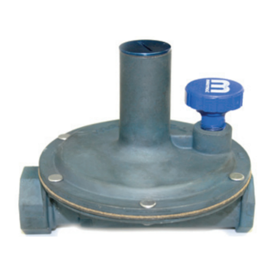
Figure 1: 325 Series Appliance Regulators
Emergency Exposure Limits
All models (Inlet Side Only)................................... 65 psi (450 kPa)
™
.
Maximum Individual Load
Largest single appliance served by the regulator.
325-3(B) .................................................................100,000 Btu/hr
325-5A(B) .............................................................. 250,000 Btu/hr
325-7A(B) ........................................................... 1,250,000 Btu/hr
Capacity
Total load of multiple appliances combined.
325-3(B) (3/8", 1/2") ................................................150,000 Btu/hr
325-5A(B) (1/2", 3/4", 1") ........................................ 300,000 Btu/hr
325-7A(B) (1 1/4", 1 1/2") .................................... 1,250,000 Btu/hr
NOTE: Capacity table is used to determine the maximum multiple
appliance load.The largest single appliance served by the
regulator should not exceed the maximum individual load
Ambient Temperature Limits
All Models .................................... -40ºF to 205ºF (-40ºC to 96ºC)
Vent Pipe Connections
325-3(B) ..........................................................................1/8" NPT
325-5A(B) ....................................................................... 3/8" NPT
325-7A(B) ........................................................................1/2" NPT
Mounting Position
The 325 Series is suitable for multi-poise
limiting device, the regulator must be
mounted in a horizontal upright position
(see Figure 2). Install the regulator
Safety Warning Instructions, GPR_MI_
EN.ES)
1
325-5A
325-5AB
sting. (See Maxitrol
Figure 2: 325 Regulator
in Upright Postion
325-7A
325-7AB
UPRIGHT
Advertisement
Table of Contents

Summary of Contents for Maxitrol 325 Series
- Page 1 Sizing Instructions ..............4 325-3 325-5A 325-7A DESCRIPTION 325 Series pounds to inches regulators are for use on residential, commercial, and industrial applications. The 325 Series features a high leverage valve linkage assembly 325-5AB 325-7AB to deliver positive dead-end lock-up. The regulators are capable of...
- Page 2 Vent Limiting Devices 325-3(B) ................12A09 325-5A(B) ................12A39 325-7A(B) ................12A49 NOTICE Maxitrol vent limiting devices eliminate the need to run vent piping to the outside. Vent limiting devices are designed for 12A09 (1/8” NPT) 12A39 (3/8” NPT) 12A49 (1/2” NPT) escapement due to diaphragm failure is critical. Vent limiting ®...
- Page 3 (98) 4 7/8 5 1/4 5 7/8 5 7/16 325-5A(B) 1/2”, 3/4”, 1” (124) (133) (149) (138) 6 1/8 7 1/4 1 1/4”, 1 1/2” 325-7A(B) (156) (184) (203) (178) 325-5A 325-3 325-7A © 2011 Maxitrol Company, All Rights Reserved.
- Page 4 325 Series Appliance Pressure Regulators SPRING SELECTION CHART Model Standard Other Springs Available Number Spring 5 to 9 7 to 11 6 to 10 7 to 11 4 to 12 2 to 6 10 to 22 15 to 30 1 to 2 psi 325-3 (1.25 to 2.25)
- Page 5 fiÀ‘‘¤Ã“ ”ÓÎÔÛÔÓÒÏ ›øø¨ß ›øƨ ±Æ Ÿø –ƪ´Æª Œª´¥ø¨±Æ ê øø¨ß ± øß Æª´¥ø¨±Æ ±¨ ø øæ±¥´¨ª ™ø¥´ªÙ æ´¨ ©¥¥ ™øÆß ©¨ ¨ª ø¥ø¨± ºªªº ± ¨ª ƪ™ø¥ ºªÆª¨ø¥Ú …ª ±ª ¨ª ±¥¥±© øƨ ©¥¥ ª¥ ß±´ ß±´Æ ª¥ª¨± ± ø ƱªÆ¥ß ¶ªº ƪ´¥ø¨±ÆÚ ”ø®¨Æ±¥...
- Page 6 ÌÓÎ Õ¤Œ¤Õ â øø¨ª ª®Æªªº ›⁄ÿ â ÚÍÏ Æ ø ”ø®¨Æ±¥ ƪ±ªºªº ø®´ ¥ª¨ ƪ´ÆªÚÚÚÚÚÚÚÚÚÚÚÚÚÚÔ ”±ºª¥ “´æªÆ –ƪ´Æª ‹Æ± ÚÌå ÚÎå ÔÚå ÌÚå ÎÚå ÈÚå ÔÒÓ ÌÒÏ Ô øº –ª Õ¶ª ÌÒË ® ÌÒË Ì...
- Page 11 180 Kehoe Boulevard Carol Stream, Illinois 60188 • USA Phone: (630) 784-1000 • (800) 253-2991 • Fax: (630) 784-1650 www.ajantunes...
- Page 12 Direct Acting or Piloted SERIES Aluminum Body Solenoid Valves 8040 qwe r 8215 1/8" to 3" NPT Features • Lightweight, low-cost valves for air service. • Ideal for low pressure applications. • Provides high flow, Cv up to 138 (Kv 118). •...
- Page 13 SERIES 8040 8215 Specifications (English units) Operating Pressure Differential (psi) Watt Rating/ Max. Class of Coil Fluid Insulation Max. AC Max. DC Temp. ˚F Aluminum Body Pipe Orifice UL Size Size Cv Flow Capacity Air-Fuel Air-Fuel Constr. Listing Btu/hr ‘...
- Page 14 SERIES 8040 8215 Specifications (Metric units) Operating Pressure Differential (bar) Watt Rating/ Max. Class of Coil Fluid Insulation Max. AC Max. DC Temp.˚C Aluminum Body Pipe Orifice Kv Flow Capacity UL Size Size Factor Air-Fuel Air-Fuel Constr. Btu/hr ‘ Listing (ins.) (mm)
- Page 15 SERIES 8040 8215 Dimensions: inches (mm) Constr. Refs. 1-4, 9, 10, 13a, 13b Constr. Ref. No. ins. 3.42 2.00 2.75 2.87 2.46 4.02 2.49 2.75 3.46 2.46 ins. 3.87 2.19 3.31 3.05 2.33 ins. 4.46 2.68 3.31 3.64 2.33 ins. 6.84 5.00 5.59...
- Page 16 Direct Acting Gas Shutoff Valves SERIES Brass Body 8262 1/8" and 1/4" NPT Features • 2-way normally closed operation • For gas pilot control of commercial and industrial gas burners • Direct lift with resilient soft seating for tight shutoff •...
- Page 17 SERIES 8262 Specifications (English units) Approx. Operating Pressure Pipe Orifice Max. Shipping Capacity x Differential (psi) Agency Size Size Flow Fluid Const. Weight (ins.) (ins.) Factor Btu/hr. Min. Max. Temp.°F Catalog Number Ref. Wattage (lbs) COMBUSTION (Fuel Gas) - NORMALLY CLOSED (Closed when de-energized) 18,700 8262H077 10.1...
- Page 20 ÔÓÒÔÒÏ –Ʊº´¨ ‹ªÆ¨± ¤¥ª fi´¨¨ªÆ¥ß ø¥™ª øƪ ºªªº ¨± ±¨Æ±¥ øÆ øº ø ¥±© ¨± ø¥¥ ¨ßª ± ±æ´¨± ߨªÚ ±´¥º ±¨ Ãߪ ø™ø¥ø楪 ø¥™ª øƪ ø™ø¥ø楪 ±Æ ª¨ªÆ ø´ø¥ ±Æ ø´¨±ø¨ ±¨Æ±¥ øº ª¨ªÆ ´¥¥ ±Æ¨ ±Æ ƪº´ªº ±Æ¨ ±¨Æ´¨±...
- Page 21 “–à ”±ºª¥ Õª¥ª¨± øº ›øø¨ª ⁄´¥¥ –±Æ¨ ø¥™ª Œªº´ªº –±Æ¨ ø¥™ª ”ø´ø¥ fl´¨±ø¨ ”ø´ø¥ fl´¨±ø¨ “–à fiª™ª¥ªº ´¨¨ªÆ fiª™ª¥ªº ´¨¨ªÆ fiª™ª¥ªº ´¨¨ªÆ “±æª™ª¥ªº ´¨¨ªÆ fiª™ª¥ªº ´¨¨ªÆ Õ¶ª ÈÎd Ʊ¨ø¨± ÈÎd Ʊ¨ø¨± ÈÎd Ʊ¨ø¨± ÌÍd Ʊ¨ø¨± ÈÎd Ʊ¨ø¨± ›ø¨ø¥± ›ø¨ø¥± ›ø¨ø¥± ›ø¨ø¥±...
- Page 22 ‹ª±Ù ”ø´ø¥ ø¥™ª ©¨ “–à ¨Æªøº ⁄À‘‘ –—ŒÃ Œ¤‹À›¤‹ –—ŒÃ ÿŸÿ –Œ¤ÕÕÀŒ¤ ‹Œ—– fiª™ª¥ªº ´¨¨ªÆ fiª™ª¥ªº ´¨¨ªÆ Á% Ʊ¨ø¨± ‹ª±Ù ª ÈÎ% Ʊ¨ø¨± ÈÎ% Ʊ¨ø¨± “–à ›ø¨ø¥± ¨ª fi—Œ¤ ›ø¨ø¥± ¨ª fi—Œ¤ ›ø¨ø¥± ¨ª fi—Œ¤ fl fi › ‹ Õ¶ª “´æªÆ...
- Page 23 Œ ”±ºª¥ Õª¥ª¨± øº ›øø¨ª ⁄´¥¥ –±Æ¨ ø¥™ª Œªº´ªº –±Æ¨ ø¥™ª ”ø´ø¥ fl´¨±ø¨ ”ø´ø¥ fl´¨±ø¨ “±æª™ª¥ªº ´¨¨ªÆ “±æª™ª¥ªº ´¨¨ªÆ “±æª™ª¥ªº ´¨¨ªÆ “±æª™ª¥ªº ´¨¨ªÆ Œ Õ¶ª ± ± ± ± Á Ʊ¨ø¨± ÌÍ Æ±¨ø¨± Á Ʊ¨ø¨± ÌÍ Æ±¨ø¨± ›ø¨ø¥± ›ø¨ø¥± ›ø¨ø¥± ›ø¨ø¥±...
- Page 24 ‹ª±Ù ”ø´ø¥ ø¥™ª ©¨ Œ ¨Æªøº ⁄À‘‘ –—ŒÃ Œ¤‹À›¤‹ –—ŒÃ ÿŸÿ –Œ¤ÕÕÀŒ¤ ‹Œ—– “±æª™ª¥ªº ´¨¨ªÆ “±æª™ª¥ªº ´¨¨ªÆ Á% Ʊ¨ø¨± ‹ª±Ù Œ Á% Ʊ¨ø¨± Á% Ʊ¨ø¨± Õ¶ª fi—Œ¤ fi—Œ¤ ›ø¨ø¥± ¨ª ›ø¨ø¥± ¨ª ›ø¨ø¥± ¨ª fi—Œ¤ fl fi ›...
- Page 25 ‹ª±Ù …øªÆ ¨ßª ™ø¥™ª ”ø´ø¥ ™ø¥™ª ¯⁄´¥¥ –±Æ¨ ø¥™ª Õ±©˜ ‹ª± ¯˜ flƱ® ›ø¨Ú ¨ª …¨Ú –±Æ¨ Õ¶ª “±Ú ›±ºª fl fi › ‹ ¤ ⁄ Ÿ ‹øÚ µ ¯¥æ˜ ⁄´¥¥ –±Æ¨ ”ø´ø¥ Œªº´ªº –±Æ¨ ”ø´ø¥ ¤ ⁄ fi Ÿ...
- Page 26 S30 Series 1/8" NPT Stainless Steel Body 2-Way Direct Acting Normally Open Materials Seals: Nitrile, Viton , Ethylene Propylene, Teflon , Rulon ® ® Orifice: Stainless Steel Electrical Standard Housing: Encapsulated Waterproof Conduit (NEMA 4/4X) Optional Housings: Metallic Conduit, Explosion-proof (NEMA 7), Grommet, Open Frame, Junction Box (single or dual knockouts), DIN;...
- Page 27 S302 – 1/8" NPT, Stainless Steel Body, Normally Open Valve Selection List Energized De-Energized Normally Open Operating Pressure Differential (psi) Model Code Power Maximum Consumption 120V/60HZ — 110V/50HZ ( Watts ) Shown Air/Gas Water Light Oil Steam* Stainless Steel Body AC DC AC DC AC DC AC DC °F 1/32...
- Page 28 S302 – 1/8" NPT, Stainless Steel Body, Normally Open Valve Selection List Energized De-Energized Normally Open Operating Pressure Differential (psi) Model Code Power Maximum Consumption 120V/60HZ — 110V/50HZ ( Watts ) Shown Air/Gas Water Light Oil Steam* Stainless Steel Body AC DC AC DC AC DC AC DC °F 1/32...
- Page 29 S302 – 1/8" NPT, Stainless Steel Body, Normally Open Part Numbering S 3 0 Seal Body Pipe Operating Series Housing* Coil Class* Voltage* Orifice Size Material Material Connection Mode 2: Normally G: Conduit F: Class F 02: 120/60 C: EPR 2: Stainless A: 1/8'' NPT C1: 1/32''...
- Page 30 flª±Æª ±Æ ø´¨±ø¨ fi K ”ø±Æ ›±±ª¨ ’¨ ›±¨Æ±¥ ”±¨±Æ ”±´¨ ’¨ ¨ª ›±ºª fiÆøµª¨ ›±¨Æ±¥ Œ±º ›±´¥ ›Æøµ flÆ ¤¥ª Œ±¨øÆß fl¨´ø¨±Æ Œÿ ±´¨Ù ÔÒÓ ¨Æ´ ÏÙ ™ªÆÚ Ô ÔÔÓÏ ÓÔÍÁÎ ÓÍÁÈ ‘ÿ ±´¨Ù ÔÒÓ ¨Æ´ ÏÙ ™ªÆÚ Ô ÔÔÓÎ...
- Page 31 catalog_page_9 Page 1 of 2 =====HOMESTEAD LUBRICATED PLUG VALVES===== Fig. 611 & 612 Standard Opening 200 lb. WOG Semi-Steel 150 lb SWP Straightway - Wrench Test: Air under water 200 Operated p.s.i.g. Rectangular Port U.L. Listed U.L. Listed 1/2" thru 4" 1' thru 6"...
- Page 32 catalog_page_9 Page 2 of 2 Center to Top of Stem (Fig. 611) Center to Top of Stem (Fig. 612) Length of Lubricant Screw Lubricant Stick Diameter Standard Wrench Size Center of Port to Bottom Dimension. of Square on Stem Extreme Width of Screwed Body Extreme Width of Flanged Body Weight, pounds - Fig.
- Page 33 flª±Æª ±Æ ø´¨±ø¨ fi K ¯±¨´ªº˜ –ªÆªº´¥øÆ fiÆøµª¨ ±Æ ¤¥ª Œ±¨øÆß fl¨´ø¨±Æ ¨ª ›±ºª ÓÔÁÌÏ ÓÔÁÌÎ ´ª ©¨ ´ª ©¨ ÔÒÓ ¨± ÔÛÔÒÓ Ó ¨± ÓÛÔÒÓ ™ø¥™ª ™ø¥™ª ÁÎ fl ¯ÌÚÈΘ ‹ ¯Ú˜ ¯Ú˜ ¨ª ›±ºª ÓÔÁÌÍ ÓÏ ÓÏ...
- Page 34 fiÀ‘‘¤Ã“ ”ÓÎÔÛÔÓÒÏ ›øø¨ß ›øƨ ±Æ Ÿø –ƪ´Æª Œª´¥ø¨±Æ ê øø¨ß ± øß Æª´¥ø¨±Æ ±¨ ø øæ±¥´¨ª ™ø¥´ªÙ æ´¨ ©¥¥ ™øÆß ©¨ ¨ª ø¥ø¨± ºªªº ± ¨ª ƪ™ø¥ ºªÆª¨ø¥Ú …ª ±ª ¨ª ±¥¥±© øƨ ©¥¥ ª¥ ß±´ ß±´Æ ª¥ª¨± ± ø ƱªÆ¥ß ¶ªº ƪ´¥ø¨±ÆÚ ”ø®¨Æ±¥...
- Page 35 ÌÓÎ Õ¤Œ¤Õ â øø¨ª ª®Æªªº ›⁄ÿ â ÚÍÏ Æ ø ”ø®¨Æ±¥ ƪ±ªºªº ø®´ ¥ª¨ ƪ´ÆªÚÚÚÚÚÚÚÚÚÚÚÚÚÚÔ ”±ºª¥ “´æªÆ –ƪ´Æª ‹Æ± øº –ª Õ¶ª ÚÌå ÚÎå ÔÚå ÌÚå ÎÚå ÈÚå ÔÒÓ ÌÒÏ Ô Ì ÌÒË ® ÌÒË ÌË...
- Page 36 flª±Æª ±Æ ø´¨±ø¨ fi K ¯±¨´ªº˜ ›Æøµ øÆ ±Æ ªªÆø¥ ´ª ›Æøµ flÆ ›Æøµ flÆ ‹” ˛fl˛ ‹” ˛fl˛ ¨ª ›±ºª ¨ª ›±ºª ¯Ú˜ ¯Ú˜ ÎÎÌÈ ÔÍÚ ¯ÚÍ̘ ÎÎÓÈ ÁÚÍ ¯ÚÌ˘ ÎÎÌË ÁÚÍ ¯ÚÌ˘ ÎÎÌÎ ÔÓÚË ¯ÚÎΘ ÎÎÌÁ ÔÓÚË...
- Page 37 10 - 30.1 - 5 Gas Electro-mechanical Valves - 10/09 Valve model number description Every MAXON gas electro-mechanical valve can be accurately identified by the model number shown on the valve nameplate. The example below shows a typical gas electro-mechanical valve model number, along with the available choices for each item represented in the model number.
- Page 38 10 - 30.1 - 6 Gas Electro-mechanical Valves - 10/09 Valve model cross reference MAXON valve model numbers have changed to intelligent coded model numbers for easy identification and specification. Valves manufactured prior to October 1, 2008 will contain an older model number system which can be easily cross referenced with the chart below.
- Page 39 10 - 30.1 - 7 Gas Electro-mechanical Valves - 10/09 Valve body assembly options & specifications Normally-closed shut-off valves Trim Special service Nominal Flow Body connections MOPD Body material package Cv rating MOPD rating pipe size capacity available rating (psig) options (psig) [1] 3/4”...
- Page 40 10 - 30.1 - 8 Gas Electro-mechanical Valves - 10/09 Normally-open vent valves Trim MOPD Special service Nominal Flow Body connections Body material package Cv rating rating MOPD rating pipe size capacity available options (psig) (psig) [1] 3/4” A, C 1, cast iron 1, 2, 4 (DN20)
- Page 41 10 - 30.1 - 9 Gas Electro-mechanical Valves - 10/09 Valve actuator options Automatic reset valves Solenoid OR Nominal Flow Normal Area Motor Motor Switch circuit board pipe size capacity position classification voltage timing options voltage 3/4” A, B, C, D, E, F, G A, B C, D, E 1, 2 0, 1, 2, 3, 4...
- Page 42 10 - 30.1 - 10 Gas Electro-mechanical Valves - 10/09 Manual reset valves Nominal Flow Normal Area Solenoid Handle side Switch pipe size capacity position classification voltage plate options options A, B, C, D, E, F, G A, B, C, D, E 0, 1, 2, 3 A, B, C, D, F, G A, B, C, D, E...
- Page 44 10 - 30.1 - 11 Gas Electro-mechanical Valves - 10/09 Valve body assembly specifications 1) Body 2) Bonnet 3) Seat 4) Disc 5) Follower ring 6) Seat o-ring 7) Body o-ring 8) Wavy spring 9) Stem 10) Spring pin 11) Stem o-ring 12) Striker plate 13) Bumper 14) Flow direction...
- Page 45 10 - 30.1 - 12 Gas Electro-mechanical Valves - 10/09 Valve body assembly - gas compatibility Agency approvals Suggested material options and certifications MOPD code rating CE [4] Body seals Body & Trim & bumper bonnet package A, B, C, E, F 1, 2, 5, 6 1, 2 Std.
- Page 47 10 - 30.1 - 13 Gas Electro-mechanical Valves - 10/09 Electrical data General MAXON shut-off valves are electrically actuated from a power source. Standard assemblies include an internal holding solenoid or clutch and printed circuit board. Position switch wiring diagrams (reproduced below) are part of each valve assembly, summarizing electrical data and wiring for a valve equipped with terminal block and a full complement of optional switches.
- Page 48 10 - 30.1 - 14 Gas Electro-mechanical Valves - 10/09 Figure 2: Normally-open valves 26379P NORMALLY OPEN VALVE VCS-1 VCS-2 VOS-1 VOS-2 Standard and CP valves L(+) N(-) SPDT SPDT SPDT SPDT DPDT DPDT VCS-2 VOS-1 GENERAL PURPOSE AREA DIVISION 2 AREA VCS-1 VOS-2 SPDT...
- Page 52 10 - 30.1 - 15 Gas Electro-mechanical Valves - 10/09 Available voltages and electrical data - General Purpose areas All MAXON valves are electrically actuated from a power source through the flame safeguard and/or safety control circuits. Standard valve assemblies include an internal holding solenoid on standard flow and CP body constructions, or a printed circuit board on high capacity valves.
- Page 53 10 - 30.1 - 16 Gas Electro-mechanical Valves - 10/09 4” and 6” high capacity valves Motor operators Printed circuit boards Voltage Power Voltage Power 115VAC, 50 Hz 667VA 115VAC, 50 Hz 13VA 115VAC, 60 Hz 391VA 115VAC, 60 Hz 13VA 230VAC, 50 Hz 25VA...
- Page 54 10 - 30.1 - 17 Gas Electro-mechanical Valves - 10/09 Available voltages and electrical data - Non-incendive areas All MAXON valves are electrically actuated from a power source through the flame safeguard and/or safety control circuits. Standard valve assemblies include an internal holding solenoid on standard flow and CP body constructions, or a printed circuit board on high capacity valves.
- Page 55 10 - 30.1 - 18 Gas Electro-mechanical Valves - 10/09 Dimensions and weights Valve bodies: 3/4” (DN20) to 3” (DN80) Body connection A & C Body connection B, D & H 1) (2) 1/4” NPT test connection Body connection E Body connection F Approximate dimensions (in inches ) Approximate weight (in lbs )
- Page 56 10 - 30.1 - 19 Gas Electro-mechanical Valves - 10/09 Valve actuators: 3/4” through 1-1/2” valves Automatic reset type (SMA11, SMA21, SMA12, SMA22) (formerly 5000, STO-A, 5000 NI, STO-A-NI) 1) (2) 3/4” NPT conduit connection 2) (2) 1/4” NPT test connection 3) Terminal block cover Manual reset type (SMM11, SMM21, SMM12, SMM22)
- Page 57 10 - 30.1 - 20 Gas Electro-mechanical Valves - 10/09 Valve actuators: 2” through 3” valves Automatic reset type (SMA11, SMA21, SMA12, SMA22) (formerly 5000, STO-A, 5000 NI, STO-A-NI) 1) (2) 3/4” NPT conduit connection 2) (2) 1/4” NPT test con- nection 3) Terminal block cover Manual reset type SMM11, SMM21, SMM12, SMM22)
- Page 58 10 - 30.1 - 21 Gas Electro-mechanical Valves - 10/09 Valve bodies: 2-1/2” CP (DN65), 3” CP (DN80), 4” CP (DN100) and 6” (DN150) Body connection A & C Body connection B, D & H 1) (2) 1/4” NPT test connection Approximate dimensions (in inches) Approximate weight (in lbs)
- Page 59 10 - 30.1 - 22 Gas Electro-mechanical Valves - 10/09 Valve actuators: 2-1/2” CP through 4” CP and 6” valves Automatic reset type (CMA11, CMA21, CMA12, CMA22) (formerly 5000 CP, STO-A-CP, 5000 NI-CP, STO-A-NI-CP) View A-A 1) (2) 3/4” NPT conduit connection 2) (2) 1/4”...
- Page 60 10 - 30.1 - 23 Gas Electro-mechanical Valves - 10/09 Valve bodies and actuators: 4” & 6” high capacity valves HMA11 versions only (formerly 7000) 1) (2) 3/4” NPT conduit connection 2) (2) 1/4” NPT test con- nection 3) Pipe size Approximate dimensions (in inches) Valve Flow...
- Page 61 10 - 30.1 - 24 Gas Electro-mechanical Valves - 10/09 Available top assembly positions The valve top assembly can be positioned on the body in four different orientations. See sketches below to determine the designation of the required orientation for your application. Position “R”...
- Page 62 10 - 30.1 - 25 Gas Electro-mechanical Valves - 10/09 Tandem arrangements (for simultaneous opening of main and blocking valves) General Wherever insurance underwriters or other regulatory groups require the use of a double-valve or “block-and-bleed” system, but manual operation is preferred to the use of automatic reset valves, operation can be simplified by adding a tandem arrangement to a pair of MAXON manual reset shut-off valves.
- Page 63 10 - 30.1 - 26 Gas Electro-mechanical Valves - 10/09 Overhead wheel & chain assembly Overhead wheel and chain assembly allows operation of a manual reset valve in an otherwise inaccessible overhead location. A wheel is mounted onto the handle of the valve. The attached chain is weighted on one end and has a paddle handgrip on the other. Once the valve is electrically energized, pulling down on the paddle will open normally-closed versions or close normally-open versions.
- Page 64 10 - 30.1 - 27 Gas Electro-mechanical Valves - 10/09 Valve actuator spare part identification 3/4” standard flow through Manual reset actuator Automatic reset actuator 4” CP actuators (side view) (side view) 1) Nameplate 2) Solenoid 3) VOS motor limit/signal switch for normally- closed valve;...
- Page 65 10 - 30.1 - 28 Gas Electro-mechanical Valves - 10/09 Please read the operating and mounting instructions before using the equipment. Install the equipment in compliance with the prevailing regulations. Bedrijfs- en montagehandleiding voor gebruik goed lezen! Apparaat moet volgens de geldende voorschriften worden geïnstalleerd.
- Page 66 10 - 30.1 - 29 Gas Electro-mechanical Valves - 10/09 The installation, operation and maintenance instructions contain important information that must be read and followed by anyone operating or servicing this product. Do not operate or service this equipment unless the instructions have been read. IMPROPER INSTALLATION OR USE OF THIS PRODUCT COULD RESULT IN BODILY INJURY OR DEATH.
- Page 67 10 - 30.1 - 30 Gas Electro-mechanical Valves - 10/09 Component identification Automatic (motorized) valve Manual valve Current model designation Current model designation (former model designation) (former model designation) SMA11 (5000), CMA11 (5000 CP), SMM11 (808), CMM11 (808 CP), SMM21 (STO-M) SMA21 (STO-A), CMA21 (STO-A-CP) 1) Access cover screws 2) Access cover...
- Page 68 10 - 30.1 - 31 Gas Electro-mechanical Valves - 10/09 Installation A gas filter or strainer of 40 mesh (0.6 mm) or smaller is recommended in the fuel gas piping to protect the downstream safety shut-off valves. Properly support and pipe the valve in the direction of the flow arrow on the valve body. Valve seats are directional. Sealing will be maintained at full rated pressures in one direction only.
- Page 69 10 - 30.1 - 32 Gas Electro-mechanical Valves - 10/09 Actuator assembly rotation MAXON electro-mechanical valves should be ordered in a configuration compatible with planned piping. If valve orientation is not correct, the actuator assembly can be rotated in 90° increments around the valve body centerline axis using the procedure below.
- Page 70 10 - 30.1 - 33 Gas Electro-mechanical Valves - 10/09 Field installation of valve position switch General Shut off fuel supply upstream of valve, then de-energize valve electrically. Remove terminal block and access cover to provide access, being careful not to damage gaskets. Compare with illustrations below to identify your valve type.
- Page 71 10 - 30.1 - 34 Gas Electro-mechanical Valves - 10/09 Wand position (for normally-closed valves) VOS switch wand should be VCS switch wand should be actuated from above actuated from below Mounting brackets Mounting bracket A Mounting bracket B VCS switch mounts on back of bracket 3”, 4”, 6”...
- Page 72 10 - 30.1 - 35 Gas Electro-mechanical Valves - 10/09 Tandem arrangements (for simultaneous opening of main and blocking valves) Installation instructions for tandem arrangements Review and comply with all general valve installation instructions provided separately. (See sketch below.) Mount both valves in fuel line with center to center spacing as originally specified, and blocking valve (without handle) down- stream of main valve (with handle).
- Page 73 10 - 30.1 - 36 Gas Electro-mechanical Valves - 10/09 To add wheel & chain assembly to existing tandem valves Verify that both valves are in the same top assembly position (TO or AW). Rotate if necessary. (See top assembly rotation instructions on page 10-30.1-33.) Bend handle of main valve outward about 25°.
- Page 74 10 - 30.1 - 37 Gas Electro-mechanical Valves - 10/09 Maintenance instructions MAXON electro-mechanical valves are endurance tested far in excess of the most stringent requirements of the various approval agencies. They are designed for long life even if frequently cycled, and to be as maintenance-free and trouble-free as possible. A valve operational test should be performed on an annual basis.
- Page 75 ›±¨Æ±¥ ”±¨±Æ ›Æøµ flÆ ¤¥ª¨Æø¥ ¤¥ª ըƱµª à ñÆØ´ª fl´®¥øÆß ”±ºª¥ ¨ª ¥´ºªº Ì ¨ª ›±ºª ‹ªÆªª Õª±º Û‘æ Õ©¨ ±¥¨ ÿ¶Ú fl ›±ºª ©Ò”±¨±Æ ¤¥ª Œ±¨øÆß fl¨´ø¨±Æ Õ¨ºÚ µªßøº fl›ÃÏflÔflÔflÔfl» Á ÔË Ì ÔÔÒÔÓ ÎÒÍ ÚÏ Ó ”±´¨ ºÆª¨¥ß ’ªßøº...
- Page 76 Õ©™ª¥ ›±ª¨±Æ ±Æ ÎÒÔÍM ‹øª¨ªÆ ›±¨Æ±¥ Œ±º ¨ª ›±ºª ÎÎÎË ø Ʊ¨ø¨ ©™ª¥ 楱µ ±ª¨±Æ ¨ª ›±ºª ÎÎÍÁ ªÆ™ª ¨± ±ª¨ ¨©± ±¨Æ±¥ Ʊº ¨± ±ª øªæ¥ß ±Æ ± ±¨Æ±¥ Ʊº ¨± ±¨Æ±¥ øÆÚ ¨ ø¥¥±© ÌÍ ±¨Æ±¥ øÆ øº ø¥± ø¥¥±© ÌÍ Æ±¨ø¨±Ú Ʊ¨ø¨±Ú...
- Page 77 ‹ø¨ø ÈÓ ÔÓÒÔÒÏ ‘¨± ÀÚÕÚflÚ...
- Page 79 Technical Instructions SQM5 Reversing Actuators Document No. 155-517P25 May 3, 2010 Features, Continued Connections for both base and face mounting Low hysteresis actuator and potentiometer gearing Externally visible position indication Selection of input and output signals Zero and span adjustment Field exchangeable circuit boards and potentiometers Electronic damper linearization function Split range and selectable parallel or master/slave operation...
-
Page 80: Table Of Contents
SQM5 Reversing Actuators Technical Instructions Document No. 155-517P25 May 3, 2010 Table Of Contents Application Page 2 Product Numbers Table 1. Product numbers for pre-assembled UL/CSA/CE-approved actuators Page 4 Table 2. Product numbers for accessories Page 5 SQM5 Product Number Identification Legend Page 6 Installation and Operating Instructions Shaft Installation... - Page 81 Technical Instructions SQM5 Reversing Actuators Document No. 155-517P25 May 3, 2010 Product Numbers Table 1. Product Numbers for Pre-assembled Actuators. Running Product Number Torque Input Control Signals [lb-in] Time 110 V 220 V 24 V 90°@ 60 Hzsec SQM50.261R1G3 SQM50.261R1G3R SQM50.261R1Z3 SQM50.264R1A SQM50.264R2A...
-
Page 82: Actuators
SQM5 Reversing Actuators Technical Instructions Document No. 155-517P25 May 3, 2010 Product Numbers Table 1. Product Numbers for Pre-assembled Actuators, Continued. Running Product Number Torque Input Control Signals [lb-in] Time 110 V 220 V 24 V 90°@ 60 Hzsec SQM56.664R1G3 SQM56.664R1G3R SQM56.664R2G3R SQM56.664R1H3... -
Page 84: Shaft Installation
SQM5 Reversing Actuators Technical Instructions Document No. 155-517P25 May 3, 2010 2. Lift the screws and raise the cover. See Figure 3. Shaft Installation Figure 3. Figure 2. 3. Each shaft is supplied with two washers and a “C” clip. See Figure 4. Using spreading pliers, remove the “C”... -
Page 85: Rotational Direction Verification
Technical Instructions SQM5 Reversing Actuators Document No. 155-517P25 May 3, 2010 Actuator model numbers that end with “R” are factory configured for clockwise (cw), Rotational Direction minimum to maximum rotation when facing the gear end of the actuator, or Verification counterclockwise (ccw) rotation when facing the other end of the actuator. -
Page 86: Shaft Adjustment
SQM5 Reversing Actuators Technical Instructions Document No. 155-517P25 May 3, 2010 Switch Adjustment, NOTE: If a potentiometer is installed, the adjustable range of the switches depends on Continued the range of the potentiometer. SQM5x.xxxxxAx actuators may be adjusted between 0 and 160 . SQM5x.xxxxxx3 actuators have a 90 potentiometer and the switches must be adjusted only between 0 and 90 . -
Page 87: Wiring Connections
Technical Instructions SQM5 Reversing Actuators Document No. 155-517P25 May 3, 2010 Wiring Connections NOTE: SQM5 actuators require a single source, single phase power supply. Wiring connections vary depending on which AGA56 . circuit board is installed. AGA56.1 circuit boards. Manual Operation See Figures 7 and 8. -
Page 88: Aga56.41/42/43
SQM5 Reversing Actuators Technical Instructions Document No. 155-517P25 May 3, 2010 Wiring, Continued Figure 8. AGA56.1A97 Terminal/Auto-Manual Board. Manual Operation AGA56.41/42/43 Circuit Boards. 1. Set the AUTO/MAN switch in the MAN position. 2. Connect ground to the screw located below the shaft release button. See Figures 9 and 10. - Page 89 Technical Instructions SQM5 Reversing Actuators Document No. 155-517P25 May 3, 2010 Wiring, Continued Figure 9. Basic Functional Diagram of AGA56.4 Figure 10. AGA56.41/42/43 Terminal and Trim Potentiometer Boards. Page 12 Siemens Building Technologies, Inc.
-
Page 90: Aga56.9 Circuit Boards
SQM5 Reversing Actuators Technical Instructions Document No. 155-517P25 May 3, 2010 AGA56.9 Circuit Manual Operation Boards Set the AUTO/MAN switch in the MAN position. See Figures 11 and 12. Connect ground to the screw located below the shaft release button. Connect neutral to terminal N. - Page 91 Technical Instructions SQM5 Reversing Actuators Document No. 155-517P25 May 3, 2010 Wiring, Continued Figure 11. Basic Functional Diagram of AGA56.9 Figure 12. AGA56.9 Terminal and Trim Potentiometer/Jumper Board. Page 14 Siemens Building Technologies, Inc.
-
Page 92: Modulation Adjustment
SQM5 Reversing Actuators Technical Instructions Document No. 155-517P25 May 3, 2010 Modulation Adjustment The blue trim potentiometers allow the adjustment of the minimum (zero) and maximum (span) positions. See Figures 10 and 12. The factory setting of the MIN trim potentiometer is rotated fully counter clockwise. The factory setting of the MAX trim potentiometer is rotated fully clockwise. -
Page 93: Cover Installation
Technical Instructions SQM5 Reversing Actuators Document No. 155-517P25 May 3, 2010 Lift the two screws on the cover corners and slide the cover end into the grooves at Cover Installation the gear end of the actuator. See Figure 14. Press the cover into place and then press the screws inward and tighten. See Figure 15. - Page 94 SQM5 Reversing Actuators Technical Instructions Document No. 155-517P25 May 3, 2010 Electronic Linearization Butterfly valves have non-linear flow characteristics. Near the fully closed position, a small Function change in the valve’s position will produce a very large change in flow. Near the fully open position, a large position change will produce a relatively small change in flow.
-
Page 95: Sqm5X.xxxxxgx Actuators
Technical Instructions SQM5 Reversing Actuators Document No. 155-517P25 May 3, 2010 Features of SQM5x.xxxxxGx actuators contain the AGA56.41A circuit board with terminals Y- and SQM5x.xxxxxGx, Y+ for 4 to 20 mA modulating input. SQM5x.xxxxxHx, SQM5x.xxxxxHx actuators contain the AGA56.42A circuit board with terminals Y, M and SQM5x.xxxxxKx U for 0 to 135 modulating input. - Page 96 SQM5 Reversing Actuators Technical Instructions Document No. 155-517P25 May 3, 2010 Reversing Rotational Direction, Continued Clockwise Counterclockwise Figure 17. Reversing Rotational Direction on the ASZ Potentiometer. Figure 17a. Reversing Rotational Direction on the ASZ Potentiometer (Gear Models). 3. Disconnect the blue and brown wires from the terminal block located on the ASZ potentiometer circuit board and reverse.
- Page 97 Technical Instructions SQM5 Reversing Actuators Document No. 155-517P25 May 3, 2010 the potentiometer gear alignment pointer Page 20 Siemens Building Technologies, Inc.
-
Page 98: Shaft Installation
SQM5 Reversing Actuators Technical Instructions Document No. 155-517P25 May 3, 2010 Reversing Rotational 8. Firmly tighten the black potentiometer cam attachment screw while manually Direction, Continued holding the potentiometer position indication pointer in alignment. Check the alignment again. 9. Re-install the white actuator-indicating dial by gently pressing it onto the potentiometer cam attachment screw. - Page 99 Technical Instructions SQM5 Reversing Actuators Document No. 155-517P25 May 3, 2010 AGA56.41/42/43 Re-install the actuator motor capacitor. Circuit Board See Figure 20. Installation, Gently guide the terminal section into the Continued support slots and slide the terminal board downward until both supports snap into place.
-
Page 100: Aga56.9A
SQM5 Reversing Actuators Technical Instructions Document No. 155-517P25 May 3, 2010 AGA56.41/42/43 Make the following connections to the Circuit Board actuator: See Figure 22. Installation, Continued a. Connect the wire, marked “1” from the circuit board to switch I, terminal 1. b. - Page 101 Technical Instructions SQM5 Reversing Actuators Document No. 155-517P25 May 3, 2010 AGA56.9A 4. Guide the base circuit board from the Circuit Board switch housing side of the actuator into Installation, Continued the bottom of the circuit board mounting bracket. See Figure 23. 5.
-
Page 102: Aga56.1A97
SQM5 Reversing Actuators Technical Instructions Document No. 155-517P25 May 3, 2010 AGA56.9A 8. Gently guide the L-shaped circuit board Circuit Board containing the three blue trim Installation, Continued potentiometers into the vertical support slots located on the cam drum side of the actuator. - Page 103 Technical Instructions SQM5 Reversing Actuators Document No. 155-517P25 May 3, 2010 Potentiometer Remove the white plastic actuator position-indicating dial by gently pulling while rotating in Removal the clockwise direction. See Figure 6. Disconnect the blue, black and brown wire from the potentiometer terminal block. See Figure 17.
- Page 104 SQM5 Reversing Actuators Technical Instructions Document No. 155-517P25 May 3, 2010 Specifications SQM5... Reversing actuator Agency approvals UL, CSA, CE SQM5... Reversing Operating voltage 24 Vac +10%-15% Actuator 110 Vac-15% to 120 Vac +10% 220 Vac-15% to 240 Vac +10% Operating frequency 50 to 60 Hz Power consumption...
- Page 105 Technical Instructions SQM5 Reversing Actuators Document No. 155-517P25 May 3, 2010 Conduit connection Two removable inserts with two Specifications 1/2-inch NPSM threads. Each insert allows insertion of entire SQM5... Reversing cable tree for easy servicing Actuator, Continued Gears and bearings Maintenance-free Mounting Bottom or face mounting possible...
- Page 106 SQM5 Reversing Actuators Technical Instructions Document No. 155-517P25 May 3, 2010 Specifications, continued AGA56.43A AGA56.43A Electronic circuit boards Same specifications as AGA56.41A except: Input signal 0 to 10 Vdc Impedance Voltage input 100K AGA56.9A Multi function electronic Single potentiometer AGA56.9A circuit boards ASZ...
- Page 107 Technical Instructions SQM5 Reversing Actuators Document No. 155-517P25 May 3, 2010 Dimensions The first dimension given is measured in inches. Millimeters are shown in parentheses. Figure 28. SQM5x.xxxRxx Dimensions. Page 30 Siemens Building Technologies, Inc.
- Page 108 SQM5 Reversing Actuators Technical Instructions Document No. 155-517P25 May 3, 2010 Dimensions, Continued Figure 29. Mounting Bracket AGA57.3. Figure 30. AGA57.4 Mounting Bracket. Siemens Building Technologies, Inc. Page 31...
- Page 110 Low Pressure Description & Features: Highly accurate reading of low pressures Brass or Stainless Steel wetted part Ranges from 10 psi to as low as 15" WC CRN Registered Applications: Suitable for measuring gaseous media both corrosive and non-corrosive Used to measure natural gas pressure as well air flow indications and leak detection Vacuum pumps, air compressors, air filters, gas burners, vacuum ovens, suction Regulators...
- Page 111 Low Pressure Specifications Brass Internals Dial: ” (63mm), 4” (100mm), 4 ” (115mm) and 6” (150mm), white aluminum dial with black and red markings Case: Steel, painted black 2.5” & 4” or cast aluminum, painted black 4.5” & 6” Lens: ”...
- Page 112 Low Pressure How to order: Specify product code PRODUCT CODES Products shown in BOLD are normally in stock. Dial Size ”(63mm) 4”(100mm) ”(115mm) 6”(150mm) Case Material Steel St/St Steel St/St Steel Aluminum Aluminum Aluminum Aluminum Center Center Center Center Connection Bottom Back Bottom Bottom Back...
- Page 113 Low Pressure 4” Back Connection Brass 4” Bottom Connection Brass 4.5” Bottom Connection Stainless Steel 4.5” Back Connection Stainless Steel 6” Bottom Connection Stainless Steel 6” Back Connection Stainless Steel .WINTERS.
- Page 114 Low Pressure Description & Features: Highly accurate reading of low pressures Brass or Stainless Steel wetted part Ranges from 10 psi to as low as 15" WC CRN Registered Applications: Suitable for measuring gaseous media both corrosive and non-corrosive Used to measure natural gas pressure as well air flow indications and leak detection Vacuum pumps, air compressors, air filters, gas burners, vacuum ovens, suction Regulators...
- Page 115 Low Pressure Specifications Brass Internals Dial: ” (63mm), 4” (100mm), 4 ” (115mm) and 6” (150mm), white aluminum dial with black and red markings Case: Steel, painted black 2.5” & 4” or cast aluminum, painted black 4.5” & 6” Lens: ”...
- Page 116 Low Pressure How to order: Specify product code PRODUCT CODES Products shown in BOLD are normally in stock. Dial Size ”(63mm) 4”(100mm) ”(115mm) 6”(150mm) Case Material Steel St/St Steel St/St Steel Aluminum Aluminum Aluminum Aluminum Center Center Center Center Connection Bottom Back Bottom Bottom Back...
- Page 117 Low Pressure 4” Back Connection Brass 4” Bottom Connection Brass 4.5” Bottom Connection Stainless Steel 4.5” Back Connection Stainless Steel 6” Bottom Connection Stainless Steel 6” Back Connection Stainless Steel .WINTERS.
Need help?
Do you have a question about the 325 Series and is the answer not in the manual?
Questions and answers
I need a new spring for my Maxitrol 325-5A natural gas regulator. I need 1 1/2 - 2 psi outlet pressure