Table of Contents
Advertisement
I N S TA L L AT I O N ,
O P E R AT I O N
A N D
SmartVu™
M A I N T E N A N C E
I N S T R U C T I O N S
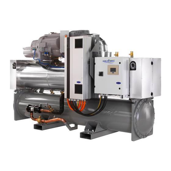
Variable-Speed Water-Cooled Liquid Chillers/
Variable-Speed Water-to-Water Heat Pumps
30XW-V/30XWHV
Nominal cooling capacity: 587-1741 kW
Nominal heating capacity: 648-1932 kW
50 Hz
Original document
Advertisement
Table of Contents

Subscribe to Our Youtube Channel
Related Manuals for Carrier AquaForce 30XW-V


Summary of Contents for Carrier AquaForce 30XW-V
- Page 1 I N S TA L L AT I O N , O P E R AT I O N A N D SmartVu™ M A I N T E N A N C E I N S T R U C T I O N S Variable-Speed Water-Cooled Liquid Chillers/ Variable-Speed Water-to-Water Heat Pumps 30XW-V/30XWHV...
-
Page 3: Table Of Contents
CONTENTS 1 - INTRODUCTION .................................... 5 1.1 - Installation safety considerations .............................. 5 1.2 - Equipment and components under pressure ..........................6 1.3 - Maintenance safety considerations ............................6 1.4 - Repair safety considerations ..............................7 2 - PRELIMINARY CHECKS ................................9 2.1 - Check equipment received ................................ - Page 4 CONTENTS 11 - STANDARD MAINTENANCE ..............................28 11.1 - Level 1 maintenance ................................28 11.2 - Level 2 maintenance ................................28 11.3 - Level 3 (or higher) maintenance ............................28 11.4 - Tightening of the electrical connections ..........................28 11.5 - Tightening torques for the main bolts and screws ......................... 29 11.6 - Evaporator and condenser maintenance ..........................
-
Page 5: Introduction
The external relief valves and the fuses are designed and shipping company. installed to ensure damage limitation in case of a fire. Carrier strongly recommends employing a specialised In accordance with the regulations applied for the design, the company to unload the machine. -
Page 6: Equipment And Components Under Pressure
Important information regarding the refrigerant used: 1.3 - Maintenance safety considerations This product contains fluorinated greenhouse gas covered Carrier recommends the following drafting for a logbook (the table by the Kyoto protocol. below should not be considered as reference and does not involve... -
Page 7: Repair Safety Considerations
Section 11.10 of this manual. purge lines or to pressurise a machine. Pressurised air Consult Carrier Service for this type of test. mixtures or gases containing oxygen can be the cause of an CAUTION: If the test leads to replacing the pressure switch, explosion. - Page 8 1 - INTRODUCTION Only use dry nitrogen for leak tests, possibly with an The refrigerant lines can break under the weight and release appropriate tracer gas. refrigerant, causing personal injury. Do not unweld or flamecut the refrigerant lines or any Do not climb on a machine.
-
Page 9: Preliminary Checks
2 - PRELIMINARY CHECKS 2.1 - Check equipment received 2.2.3 - Checks before system start-up • Inspect the unit for damage or missing parts. If damage is Before the start-up of the refrigeration system, the complete detected, or if shipment is incomplete, immediately file a installation, ... -
Page 10: Dimensions, Clearances
3 - DIMENSIONS, CLEARANCES 3.1 - 30XW-V/30XWHV 580-880 Evaporator Condenser Dimensions in mm 30XW-V/30XWHV 1743 968 1087 3059 168,3 168,3 2900 1743 968 1087 3059 168,3 168,3 2900 1950 1083 1237 3290 219,1 219,1 3100 1950 1083 1237 3290 219,1 219,1 3100 Legend All dimensions are given in mm. -
Page 11: 30Xw-V/30Xwhv 1150-1710
3 - DIMENSIONS, CLEARANCES 3.2 - 30XW-V/30XWHV 1150-1710 Evaporator Condenser Legend All dimensions are given in mm. Required clearances for maintenance Recommended space for tube removal Water inlet Water outlet Power supply connection Dimensions in mm NOTES: • Drawings are not contractually binding. Before design-ing 30XW-V/30XWHV an installation, consult the certified dimensional 1150... -
Page 12: Physical And Electrical Data
4 - PHYSICAL AND ELECTRICAL DATA 4.1 - Physical data 30XW-V/30XWHV 1150 1280 1470 1570 1710 Sound levels - standard unit Sound power level dB(A) Sound pressure level at 1 m dB(A) Sound levels - standard unit + option 257 Sound power level dB(A) Sound pressure level at 1 m... -
Page 13: Electrical Data
4 - PHYSICAL AND ELECTRICAL DATA 4.2 - Electrical data 30XW-V/30XWHV 1150 1280 1470 1570 1710 Power circuit Nominal power supply V-ph-Hz 400-3-50 Voltage range 360-440 Control circuit 24 V via the built-in transformer Start-up current Negligible (lower than maximum current drawn) 0,91- 0,91- 0,91-... -
Page 14: Short-Circuit Stability Current For All Units
(IPC) to which other • The Carrier 30XW-V/30XWHV units are designed and built to ensure conformance loads are connected are described in standard 61000-2-4. with local codes. The recommendations of European standard EN 60204-1... -
Page 15: Electrical Connection
Wire sizing is the responsibility of the installer, and depends on the the Carrier warranty. If the phase imbalance exceeds 2% for characteristics and regulations applicable to each installation site. voltage, or 10% for current, contact your local electricity supplier... -
Page 16: Field Control Wiring
5 - ELECTRICAL CONNECTION 5.6 - Field control wiring 5.7 - 24 and 230 V power reserve for the user Important: Field connection of interface circuits may lead to Control circuit reserve: safety risks: any control box modification must maintain After all required options have been connected, the TC transformer equipment conformity with local regulations. -
Page 17: Application Data
6 - APPLICATION DATA 6.1 - Operating limits 6.3 - Minimum chilled water flow The minimum chilled water flow is shown in the table in chapter 30XW-V/30XWHV Minimum Maximum 6.7 “Evaporator and condenser water flow rates”. If the system flow is less than the minimum unit flow rate, the Evaporator evaporator flow can be recirculated, as shown in the diagram. Entering temperature at start-up 35,0°C Leaving temperature during operation 3,3°C 20,0°C For minimum chilled water flow rate... -
Page 18: Number Of Passes
Delta_T > 3 K at the evaporator and the condenser To achieve a temperature difference of 3 K at the condenser, Carrier recommends the installation of option 102C. To achieve a temperature difference of 3 K at the evaporator, Carrier recommends the installation of option 100C. -
Page 19: Variable Flow Evaporator
6 - APPLICATION DATA 6.9 - Variable flow evaporator Units with one evaporator pass (option 100C) Variable evaporator flow can be used. The controlled flow rate must be higher than the minimum flow given in the table of permissible flow rates and must not vary by more than 10% per minute. If the flow rate changes more rapidly, the system should contain a minimum of 6.5 litres of water per kW instead of 3.25 l/kW. -
Page 20: Water Connections
7 - WATER CONNECTIONS ATTENTION: Before carrying out any water connections Carrier recommendations on heat exchange fluids: install the water box purge plugs (one plug per water box in • No NH ammonium ions in the water, they are very the lower section - supplied in the control box). -
Page 21: Water Connections
IMPORTANT: On 30XW-V/30XWHV units, the unit water flow or tightening must be done in accordance with the illustration in switch must be energised. Failure to follow this instruction the example below. will void the Carrier guarantee. The water flow switch is installed on the evaporator water inlet Water box tightening sequence and adjusted by the control, based on unit size and application. If ... -
Page 22: Operation Of Two Units In Master/Slave Mode
7 - WATER CONNECTIONS 7.5 - Operation of two units in master/slave mode The control of a master/slave assembly is in the entering water and does not require any additional sensors (standard configuration). It can also be located in the leaving water. In this case two additional sensors must be added on the common piping. All parameters, required for the master/slave function must be configured using the MST_SLV menu. -
Page 23: Heat Pumps 30Xwhv
8 - HEAT PUMPS 30XWHV 8.1 - Physical data for heat pumps The physical data for 30XWHV for heat pumps are the same as for the 30XW-V units. Please refer to chapter 4.1. 8.2 - Electrical data for heat pumps The electrical data for 30XWHV for heat pumps are the same as for the 30XW-V units. -
Page 24: Major System Components And Operation Data
• It is normally required that the user or operator sets up and they are applied. This is also the case for the products originally maintains a monitoring and maintenance file. supplied by Carrier. • If no regulations exist or to complement regulations, follow 9.6.7 - Condenser and oil separator the control programmes of EN 378. -
Page 25: Srmcr High-Pressure Safety Circuit
9 - MAJOR SYSTEM COMPONENTS AND OPERATION DATA 9.7 - SRMCR high-pressure safety circuit 9.7.3 - Restarting after high pressure is detected After overpressure is detected, it is necessary to manually reset 9.7.1 - General description the switched HPS. A blunt tool with a diameter of less than 6 mm must be used for this. -
Page 26: Options
10 - OPTIONS Use for 30XW-V Options Description Advantages range Implementation of new algorithms of control to Matches with most application 580-1710 (see Light-brine solution, down to allow chilled brine solution production down to requirements for ground-sourced heat dedicated -3°C -3°C when ethylene glycol is used (0°C with pumps and fits with many industrial ... - Page 27 10 - OPTIONS Use for 30XW-V Options Description Advantages range Valve replacement and inspection Dual relief valves on 3-way 194 Three-way valve upstream of dual relief valves facilitated without refrigerant loss. 580-1710 valve on the evaporator and the oil separator Comforms to European standard EN378/ BGVD4 Additional tests on the water heat exchangers.
-
Page 28: Standard Maintenance
HVAC unit Simple procedure can be carried out by the user: nul and void, and the manufacturer, Carrier France, will no • Visual inspection for oil traces (sign of a refrigerant leak) longer be held responsible. -
Page 29: Tightening Torques For The Main Bolts And Screws
The switch that has been selected for detecting reverse rotation 3/8 ORFS nut Oil line is Carrier part number HK01CB001. This switch opens the contacts H M6 screw Stauff collar when the pressure falls below 7 kPa. The switch is a manual reset... -
Page 30: Frequency Variator Maintenance
This procedure must be repeated for each circuit of the unit. For any other alarm or problem at the frequency variator, contact the Carrier service department. 1. Set up a calibrated pressure gauge on the high pressure part of the circuit (compressor discharge) -
Page 31: Final Shutdown
12 - FINAL SHUTDOWN 12.1 - Shutting down Separate the units from their energy sources, allow them to cool then drain them completely. 12.2 - Recommendations for disassembly Use the original lifting equipment. Sort the components according to their material for recycling or disposal, in accordance with regulations in force. Check whether any part of the unit can be recycled for another purpose. -
Page 32: Start-Up Checklist For 30Xw-V/30Xwhv Units (Use For Job File)
13 - START-UP CHECKLIST FOR 30XW-V/30XWHV UNITS (USE FOR JOB FILE) Preliminary information Job name: ........................................ Location: ........................................Installing contractor: ....................................Distributor: ....................................... Unit Model: ........................................Compressors Circuit A Model number......................................Serial number ......................................Motor number ......................................Circuit B Model number......................................Serial number ...................................... - Page 33 WARNING: Operation of the unit with an improper supply voltage or excessive phase imbalance constitutes abuse which will invalidate the Carrier warranty. If the phase imbalance exceeds 2% for voltage, or 10% for current, contact your local electricity supplier at once and ensure that the unit is not switched on until corrective measures have been taken.
- Page 36 CARRIER participe au programme ECP dans la catégorie LCP/HP Vérifier la validité actuelle du certificat : www.eurovent-certification.com Réf. de commande : 13474, 11.2020. Remplace la réf. de commande : 13474-76, 12.2017. Fabricant : Carrier S.C.S, Montluel, France. Le fabricant se réserve le droit de changer sans préavis les spécifications du produit.
Need help?
Do you have a question about the AquaForce 30XW-V and is the answer not in the manual?
Questions and answers