Table of Contents
Advertisement
Quick Links
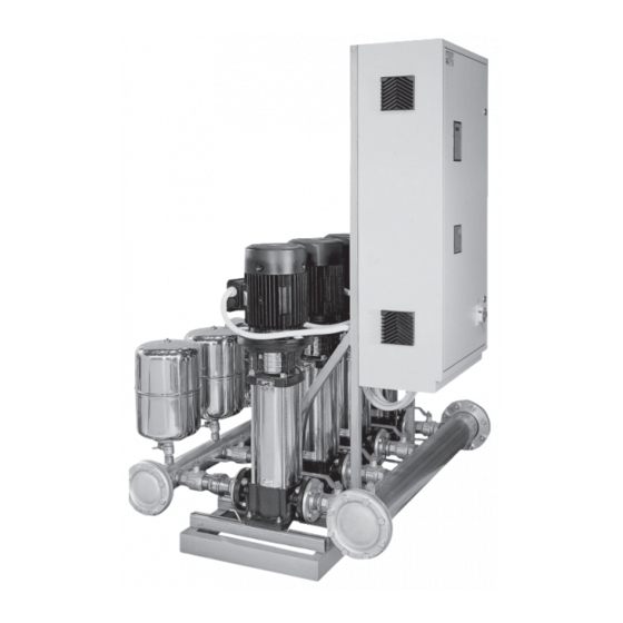
GRUPPI DI PRESSIONE A VELOCITA' VARIABILE
FREQUENCY - CHANGER
I
Manuale di uso e manutenzione
GB
Use and maintenance manual
F
Manuel d'utilisation et d'entretien
D
Bedienungs - und Wartungsanleitung
pag. 1
E
Manual de uso y manutenciòn
,, 12
NL
Handleiding voor gebruik en onderhound
,, 23
PL
Recyzny uzywaine i obslugi
,, 34
Bycnherwbb
Bycnherwbb
Bycnherwbb
Bycnherwbb
Bycnherwbb
RUS
a e y r w b j y b h j d f y b /
a e y r w b j y b h j d f y b /
a e y r w b j y b h j d f y b /
a e y r w b j y b h j d f y b /
a e y r w b j y b h j d f y b /
pag. 45
gj
gj
ecnfyjdrt
ecnfyjdrt
b
b
gj
gj
gj
ecnfyjdrt
ecnfyjdrt
ecnfyjdrt
b
b
b
,, 56
,, 67
,, 78
Advertisement
Table of Contents

Related Manuals for Nocchi FCD20/VLR16 Series


Summary of Contents for Nocchi FCD20/VLR16 Series
- Page 1 GRUPPI DI PRESSIONE A VELOCITA’ VARIABILE FREQUENCY - CHANGER Manuale di uso e manutenzione pag. 1 pag. 45 Manual de uso y manutenciòn ,, 12 ,, 56 Use and maintenance manual Handleiding voor gebruik en onderhound ,, 23 ,, 67 Manuel d’utilisation et d’entretien Recyzny uzywaine i obslugi ,, 34...
- Page 2 CONTENTS Chap.1 – General information Chap.6 – Starting up Chap.2 – Limits of use Chap.7 – Modification in configuration and working Chap.3 – Hydraulic Installation parameters Chap.4 – Priming of the group Chap.8 – Failure messages Chap.5 – Electric connection Chap.9 –...
- Page 3 To reduce losses during replenishment it is necessary to install the group as close as possible to the pumping point and to install a suction pipe with a minor number of curvatures that should have a sufficiently wide radius. Even the diameter of the pipe should be calculated so as to reduce load losses, what requires dimensions greater than or equal to those of the motor pump aspiration inlet.
- Page 4 The following message (1) will be displayed NOCCHI PUMPS Bar 05.0 - a small bell will give out a set of beeps LINEA...
- Page 5 MANUAL FUNCTION Bar 05.0 The installation is prepared for MANUAL working Push key (2) : n.1 pump will enter in function; push again the same key to stop the pump and to control the sense of rotation of pump n.2 pump therefore the one of all other. In the case where pumps would not turn all in the same sense, before proceeding to the correction check sense of rotation of pumps directly fed (and no from an inverter).
- Page 6 LINEA Wait some seconds and send current to the switchboard: the green LED will lit and the small bell will give out some beeps. The following message will be displayed: NOCCHI PUMPS Bar 05.0 The green LED will lit. From this moment the groups will function automatically according to water flow withdrawn by the user.
- Page 7 To exit from the programming mode press several times key (19) PROGR. MENU PROGR. MENU PROGR. MENU EXIT TEMP. KICK STOP INVERSION NOCCHI PUMPS MANUAL FUNCTION Bar 05.0 Bar 10.0 By pressing key (17) the unit will begin to function in AUTOMATIC Chap.7–Change configuration and operational parameters See fig.7-8...
- Page 8 TRANSDUCER VALUE MAX Bar 10 - Line n.1 TRANSLATOR Non modifiable description - Line n.2 VALUE MAXIMUM BAR XX The maximum value of the pressure transducer must be entered. Normally in our standard groups a transducer 0-5V 0-10 bar is used, therefore value 10 must be entered for this transducer. MENU ACCESS TOTAL YES/NO - N.1 line ACCESS MENU...
- Page 9 MENU PROGR. TEMP. KICK STOP Press key (20) ENTER K.S DELAY. 10 05 KS identifies the function inserted for stopping the pump controlled by the inverter. At time intervals corresponding to the KS value established, the inverter feeds the pump at the maximum frequency (50 Hz) during the time set in menu 7b - length KS.
- Page 10 Note The number of pumps that do not compose the group has no connection with the numbering used by the microprocessor program. In fact the program logic considers as pump 1 the one that leaves first; pump 2 the one that leaves for second and so on.
- Page 11 Cyclic inversion logics: at every beginning of the working cycle, the pump which has been last started is enabled first. During the working of the group the pumps controlled directly are stopped in reverse order respect to the one start up order. Example: GROUP WITH 4 PUMPS First pump started up controlled by the inverter of pumps 2...
- Page 12 Chap.9–Exclusion of the inverter In case of breakdown of the inverter, while waiting for the appropriated repair intervention, the group can operates automatically or manually: 1) Automatic operation The motor pumps are operated by an SFC card on pressure levels. In this case it is necessary to cut the voltage off the switchboard and open the protective fuse-holder of the inverter (see fig.3).
- Page 13 AUTOCLAVE WITH SYMBOLS USED MEMBRANE DIAGRAM Electropump Float valve On-off valve Check valve Standing valve with filter Level control electrode Level switch Gauge - Vacuum gauge Hydraulic circuit breaker Flexible coupling USER ELECTRIC ELECTRIC ELECTRIC POWER SUPPLY POWER SUPPLY POWER SUPPLY FC 30/ GROUP...
- Page 16 LEVEL CONTROL CONNECTION TERMINAL BOARD DEVICES OUTSIDE ELECTRIC BOARD MINIMUM PRESSURE NO CONTROL FLOAT ELECTROPROBE SWITCH LEVEL CONTROL REMOVE THE PRESSURE JUMPERS AND TIMER FOR SENSOR TIMED CONNECT THE EXCHANGE CONTROL OF (OPTIONAL) SELECTED LEVEL PRESSURE GROUPS FREQUENCY CHANGER MODEL ELECTRIC BOARDS AND ELECTRONIC CARD KEYBOARD CONTROL BOARD WITH INVERTER BOARD...
- Page 17 FREQUENCY CHANGER DIAGRAM FLOW DIAGRAM OF THE MENUS AND FAULT MESSAGES NOCCHI PUMPS Bar 05.0 MANUAL FUNCTION FAULT MESSAGES Bar 05.0 BY KEEPING PRESSED FOR 10” BY KEEPING PRESSED FOR 2” STOP FOR LOW WATER LEVEL NUMBER OF PUMPS 5 SYSTEM INVERTER STAB.
- Page 18 PUMP No. 1 PUMP No. 2 DIRECT DIRECT AUTOMATIC AUTOMATIC START START CARD CARD TEST TEST CUT-OUT CUT-OUT PUMP No. 1 PUMP No. 2 PUMP No. 3 DIRECT DIRECT DIRECT AUTOMATIC AUTOMATIC AUTOMATIC START START START CARD CARD CARD TEST TEST TEST CUT-OUT...
Need help?
Do you have a question about the FCD20/VLR16 Series and is the answer not in the manual?
Questions and answers